Hi and thanks for using 2CarPros.
Here are the directions specific to your vehicle for belt replacement. All attached pictures correlate with these directions.
PROCEDURES
Timing Belt
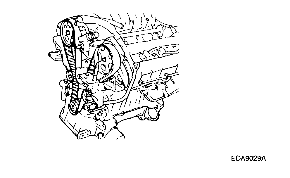
Picture 1
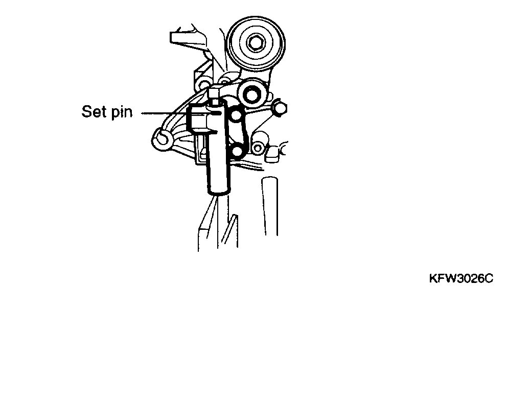
Picture 2
Removal
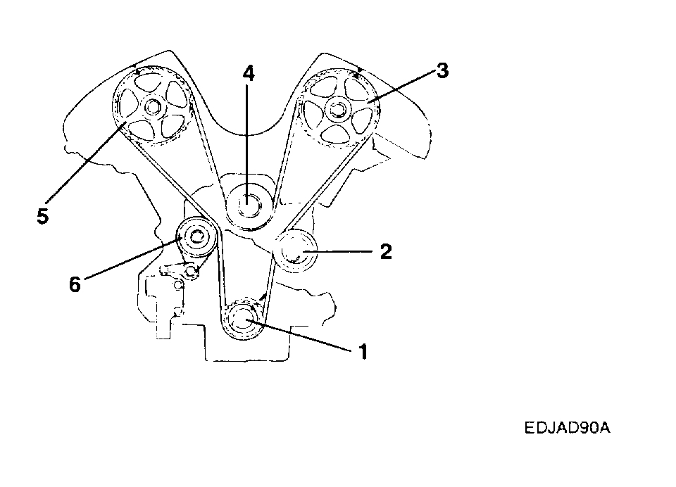
Picture 3
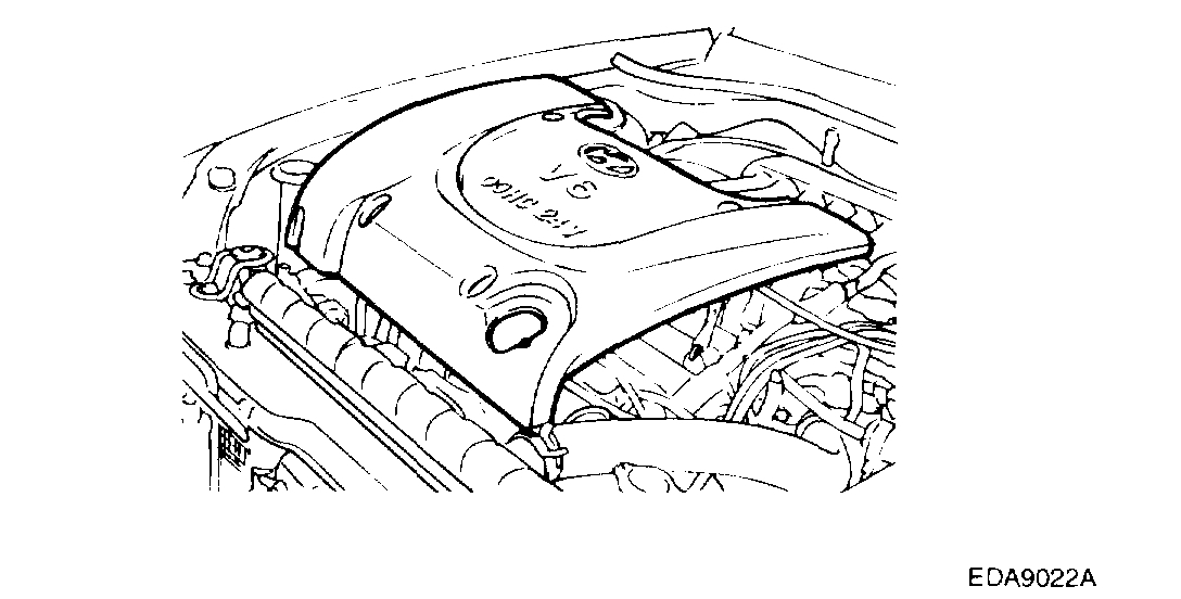
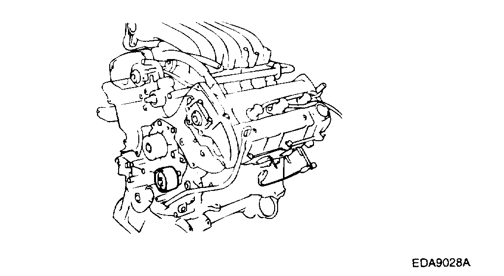
1. Remove the engine cover.
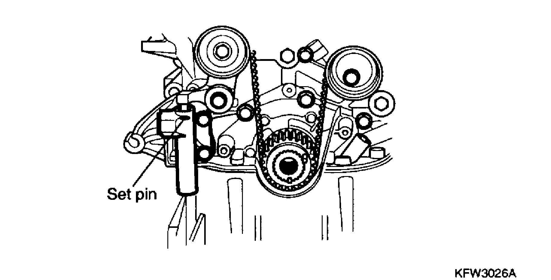
Picture 4
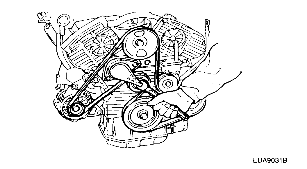
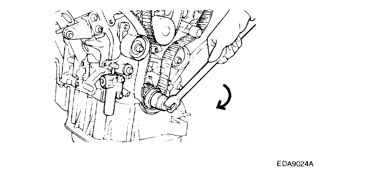
2. Using a [16 mm], rotate the tensioner arm clockwise (about 14°) and remove the belt from the pulley.
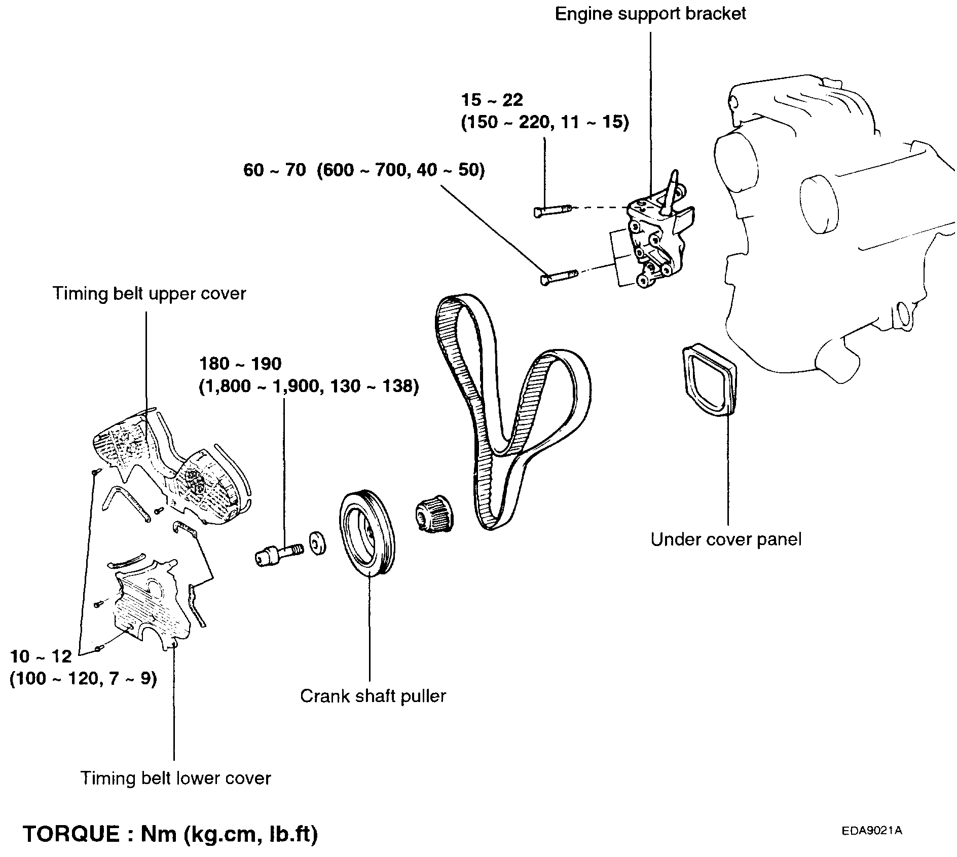
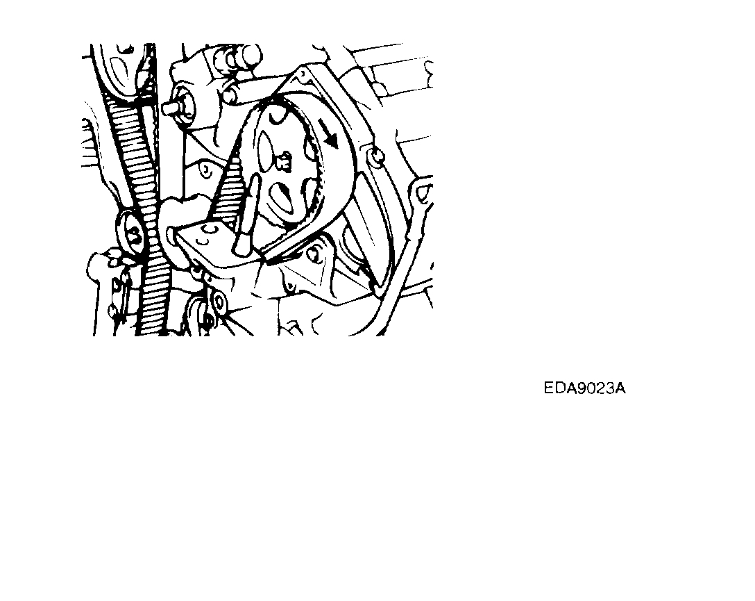
3. Remove the power steering pump pulley, idler pulley, tensioner pulley and crankshaft pulley.
Picture 5
4. Remove the upper and lower timing belt covers.
Picture 6
5. Remove the auto tensioner.
Note: Rotate the crankshaft clockwise and align the timing mark to set the No. 1 cylinder's piston to TDC (compression stroke).
At this time, the timing marks of the camshaft sprocket and cylinder head cover should coincide with each other.
Picture 7
6. Unbolt the tensioner to remove the timing belt.
Note: If you plan to use the timing belt again, mark the rotation direction on the belt so you reinstall it correctly.
Inspection
1. Inspect the belt closely. If the following problems are evident, replace the belt with a new one.
Picture 8
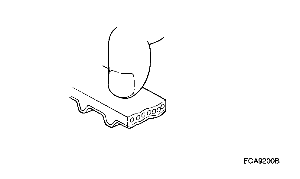
1) Hardened back surface of rubber Back surface is glossy, non-elastic and so hard that when the nail of your finger is pressed into it, no mark is produced.
Picture 9
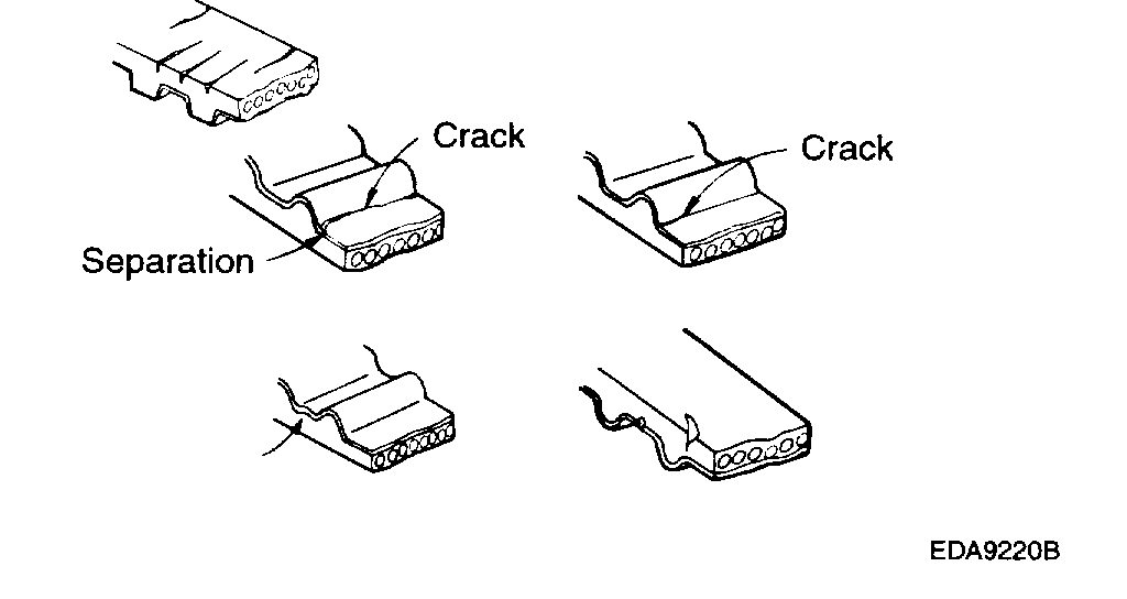
2) Cracked back surface of rubber.
Picture 10
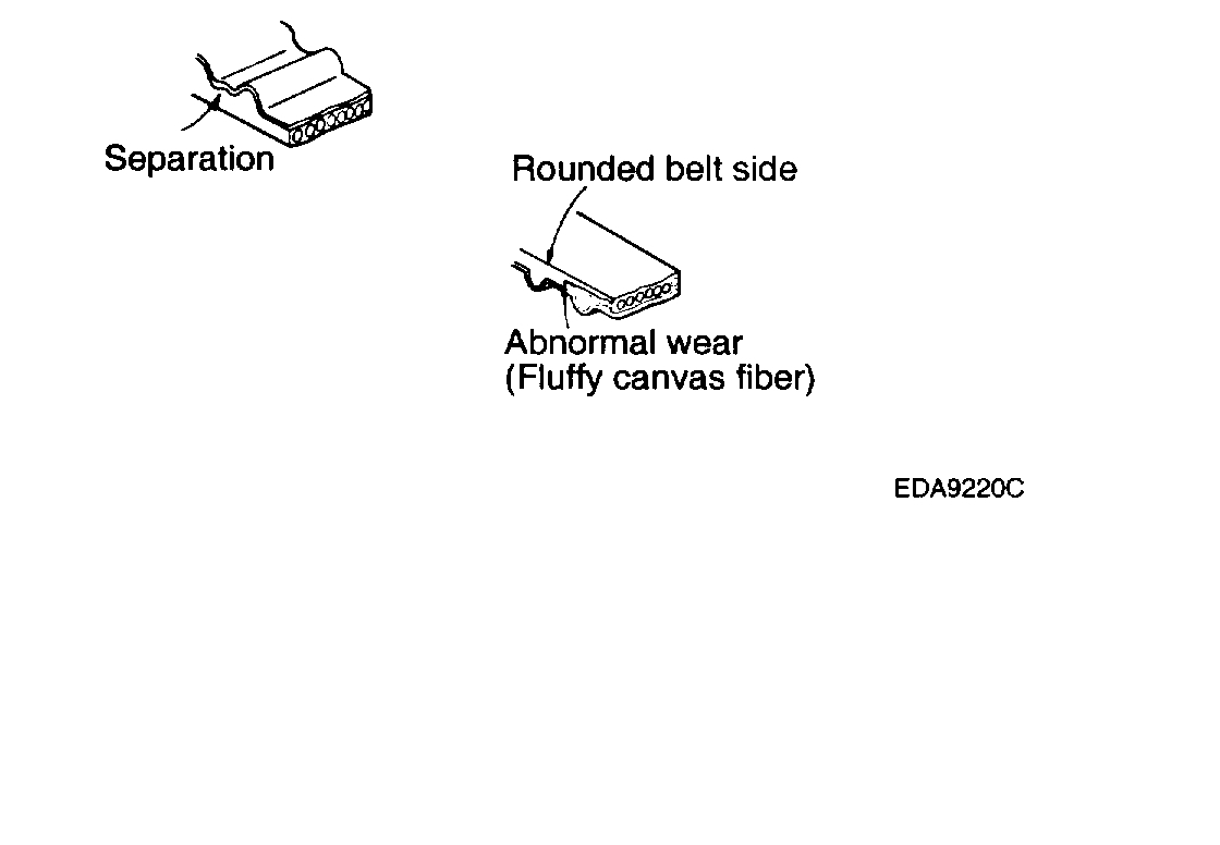
3) Side of belt is badly worn.
Note: A belt in good condition should have clear-cut sides as if it were cut with a sharp knife.
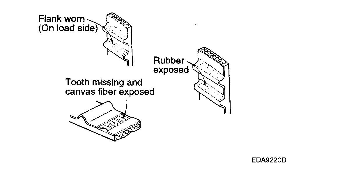
4) Teeth are badly worn out.
Initial stage: Canvas on load side of the tooth flank worn (fluffy canvas fibers, rubber gone, color changed to white, and unclear canvas texture)
Last stage: Canvas on the load side of the tooth flank worn down and rubber exposed (tooth width reduced).
Picture 11
5) Missing tooth
Picture 12
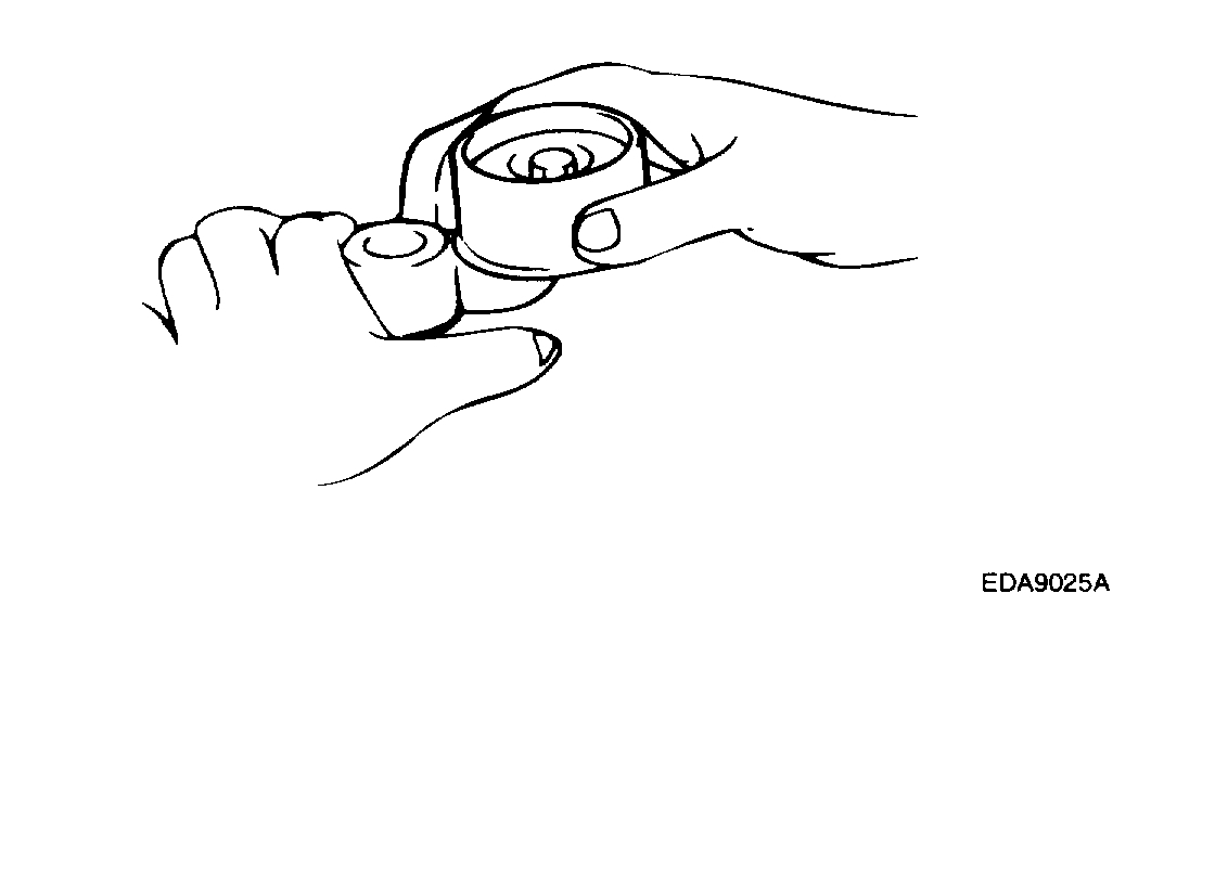
2. If backlash or an irregular noise is observed when rotating the pulley, replace the timing belt tensioner and idler pulley.
Installation
Picture 13
1. Install the idler pulley to water pump boss.
Note: Insert and install the idler pulley to the roll pin that is pressed in the water pump boss.
2. Install the tensioner arm and plain washer to the cylinder block.
3. Install the tensioner pulley to the tensioner arm.
Picture 14
4. Install the camshaft sprockets and align the timing marks.
Note:
- When installing the camshaft sprockets, fasten them tightly while holding the hexagonal part of the camshaft.
- Before installing the timing belt, if the timing marks of the cam sprocket and the cylinder head cover do not coincide, do not rotate the cam sprocket more than 3 teeth in either direction.
- Rotating the sprocket more than 3 teeth may allow the valve and piston to touch each other.
- If the cam sprocket is rotated more than 3 teeth unavoidably, rotate the crankshaft counter-clock wise a bit before rotating the cam sprocket.
Picture 15
5. Install the auto tensioner to the front case.
Note:At this time auto tensioner's set pin should be compressed and secured with set pin.
Picture 16
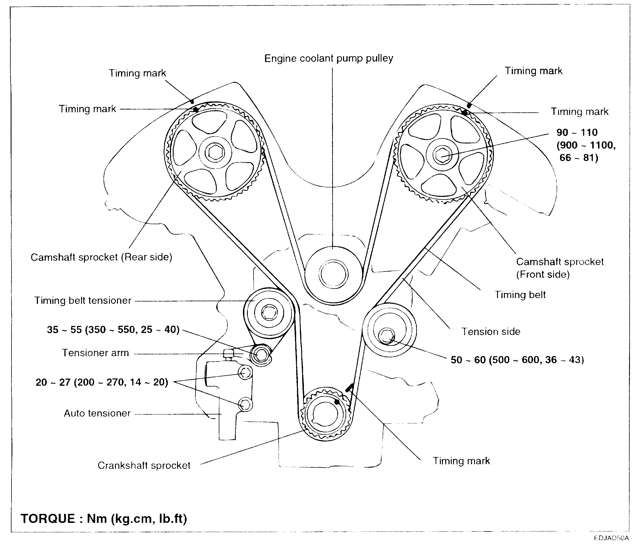
6. Align the timing marks of each sprocket and install the timing belt in the following order.
1. Crankshaft sprocket
2. Idler pulley
3. Camshaft sprocket (LH side)
4. Water pump pulley
5. Camshaft sprocket (RH side)
6. Tensioner pulley
Note:
- In this step, No. 1 cylinder is in the TDC (Compression stroke).
- Be very careful if you use your fingers.
Picture 17
7. Pull out the set pin of the auto tensioner.
8. Install the upper and lower timing belt covers.
9. Install the power steering pump pulley, idler pulley, tensioner pulley and crankshaft pulley.
10. Using the wrench [16 mm], rotate the tensioner arm clockwise (about 14°) and install the belt to the pulley.
11. Install the engine cover.
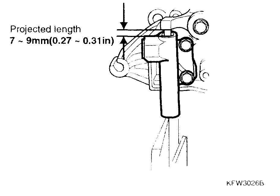
How To Adjust The Tension Of The Timing Belt
1. Rotate the crankshaft 2 turns clockwise and measure the projected length of the auto tensioner at TDC (# 1 Compression stroke) after 5 minutes.
2. The projected length should be 7-9 mm.
Picture 18
3. Verify that the timing marks of each sprocket are in their specified position.
Note: If the timing marks are not in their specified position, repeat from 6 above (in the installation procedure).
___________________________________________'
Let me know if this helps or if you have other questions.
Take care,
Joe
Images (Click to make bigger)
Friday, February 22nd, 2019 AT 11:05 PM