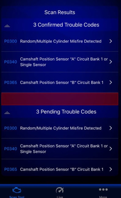
Well, those are the circuit codes for both bank one sensors. However, because they are circuit codes and because it is rare for both sensors to fail at the same time I would actually look for wiring damage before replacing them. Both use the same power feed and ground as the other sensors which are working but the wiring for both bank one sensors runs in the same harness and it would be easy for that harness to rub on the cylinder head or on a bracket and have the wires damaged. (and it is a common failure on that engine)
To test the wiring you need a simple test meter that can read ohms and volts. (even a cheap one will do those functions)
https://www.2carpros.com/articles/how-to-use-a-voltmeter
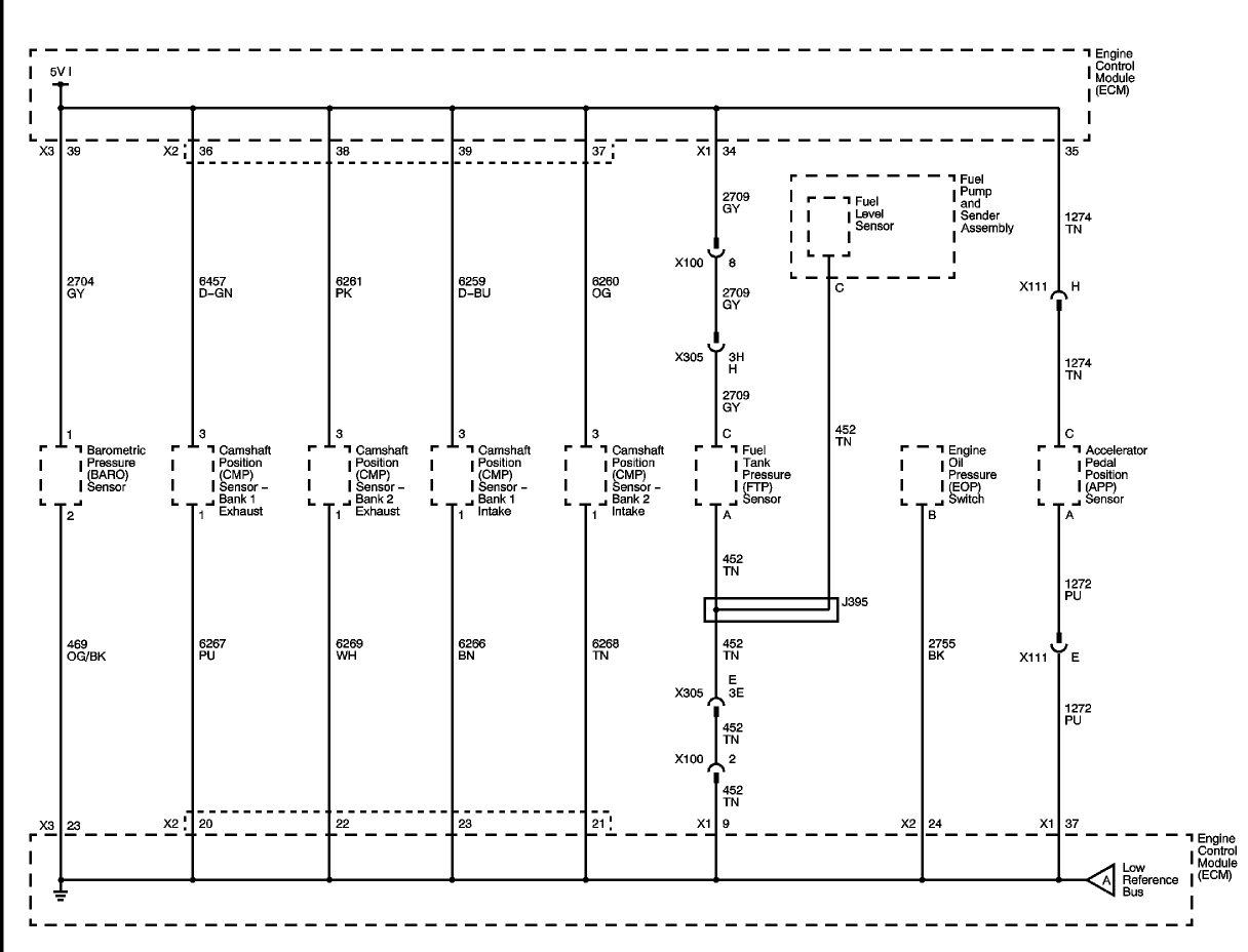
The first image is the wiring to the sensors. The ones you are having an issue with are both of the bank one sensors. They will have three wires on them. One will have 5 volts with the ignition on. Another is the ground side and it should be grounded all the time. Then there is the third wire which is the signal wire to the computer.
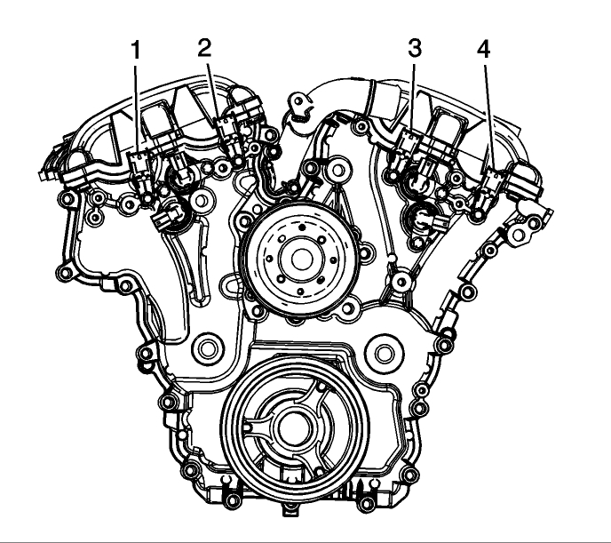
The second image are the sensor locations. They are on the cylinder heads on the side opposite the transmission.
1 is the exhaust cam sensor Bank 1 (firewall side head).
2 is the intake cam sensor Bank 1.
3 is the intake cam sensor Bank 2 (radiator side head).
4 is the exhaust cam sensor Bank 2.
1 and 2 are the ones showing the fault so I would look at the wiring carefully.
To test you start with the ignition off.
Now unplug the two wiring connectors from the sensors.
Connect the black lead of the tester to a good ground (battery negative is good for this or a good clean spot on the engine)
Select volts DC and test it by touching the battery positive post. You should see around 12 volts with a good battery.
Next turn the key on. Now gently touch each pin in the harness side of the connectors. On each one you should find one wire with 4.5 - 5 volts
For the EX sensor it should be the dark green wire, for the intake it is dark blue.
That is the bias voltage to each sensor.
Now turn the key off.
Set the meter to read ohms now touch the battery negative post with the red probe. On some meters this will cause a beep on others it will just show very close to zero ohms.
Back to the connectors verify that the key is off. Now probe the brown wire in the intake connector and the purple wire in the exhaust connector. Those are the ground wires and should show the same reading as touching the probe to the negative/ground.
If all four of those tests show that the wires are good the next step requires a scan tool that can read live data or an oscilloscope, those are needed to watch the signals from the sensors to see if the PCM is actually getting them.
I suspect you will find damaged wires before needing the scan tool.
Images (Click to enlarge)
Jun 21, 2018 at 11:39 PM