Have you installed the tensioners?
_____________________
Here are the directions for chain replacement from start to finish. Take a look through them and see if they help. The attached pics correlate with the directions.
____________________
2004 Toyota Camry L4-2.4L (2AZ-FE)
Procedures
Vehicle Engine, Cooling and Exhaust Engine Timing Components Timing Chain Service and Repair Procedures
PROCEDURES
Part 1 Of 3
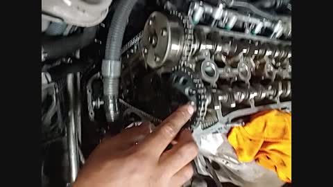
pic 1
Part 2 Of 3
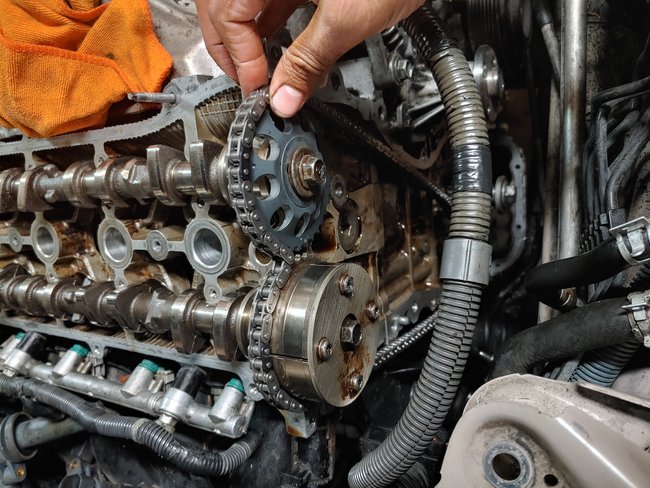
pic 2
CHAIN
REPLACEMENT
1. REMOVE HOOD SUB-ASSY
2. REMOVE FRONT WHEEL RH
3. REMOVE ENGINE UNDER COVER LH
4. REMOVE ENGINE UNDER COVER RH
5. REMOVE FRONT FENDER APRON SEAL RH
6. DRAIN ENGINE OIL
a) Install a new gasket and the drain plug after draining engine oil.
Torque: 25 Nm (255 kgf-cm, 18 ft. Lbs.)
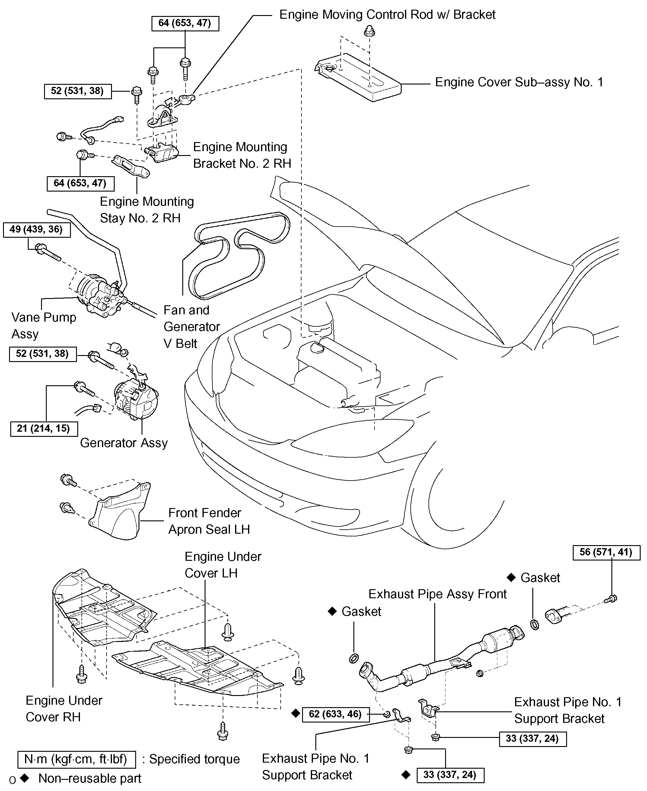
7. REMOVE EXHAUST PIPE ASSY FRONT
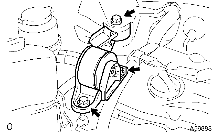
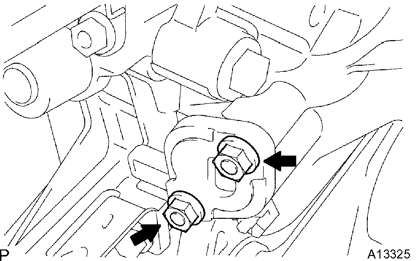
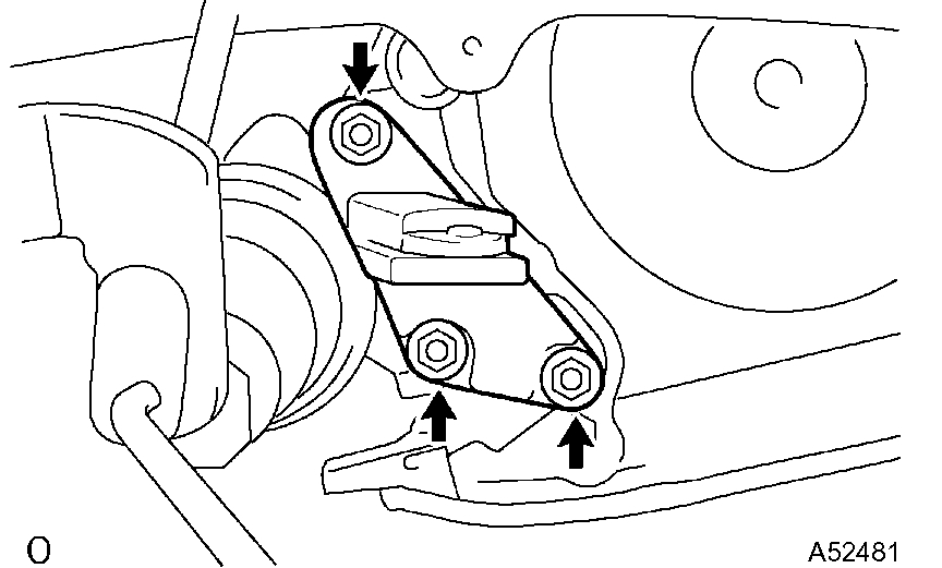
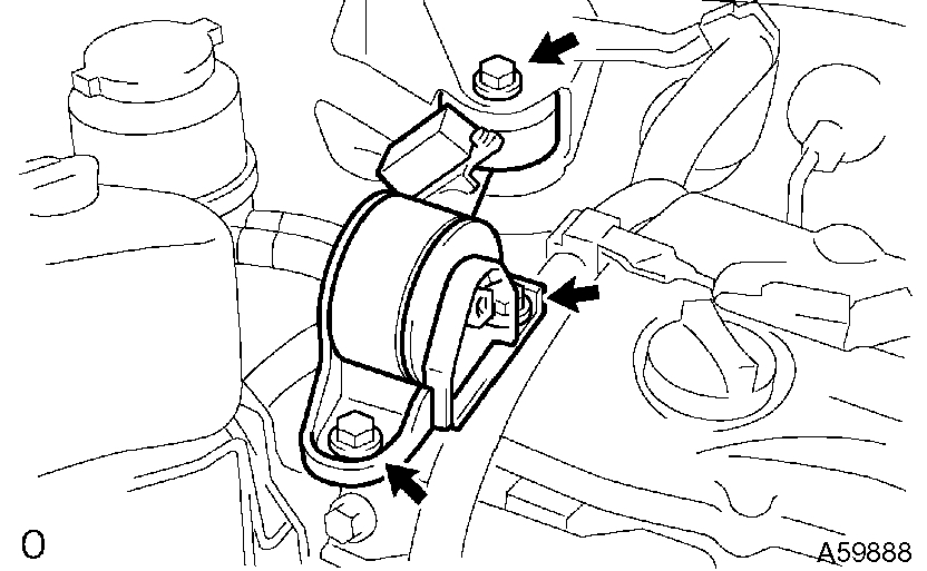
8. REMOVE ENGINE MOVING CONTROL ROD W/BRACKET
pic 3
a) Remove the 3 bolts and control rod.
9. REMOVE ENGINE MOUNTING STAY NO.2 RH
10. REMOVE ENGINE MOUNTING BRACKET NO.2 RH
11. REMOVE FAN AND GENERATOR V BELT
12. REMOVE ENGINE COVER SUB-ASSY NO.1
13. DISCONNECT ENGINE WIRE
14. REMOVE GENERATOR ASSY
15. REMOVE VANE PUMP ASSY
NOTICE: Do not disconnect the hose.
16. REMOVE IGNITION COIL ASSY
17. DISCONNECT VENTILATION HOSE
18. DISCONNECT VENTILATION HOSE NO.2
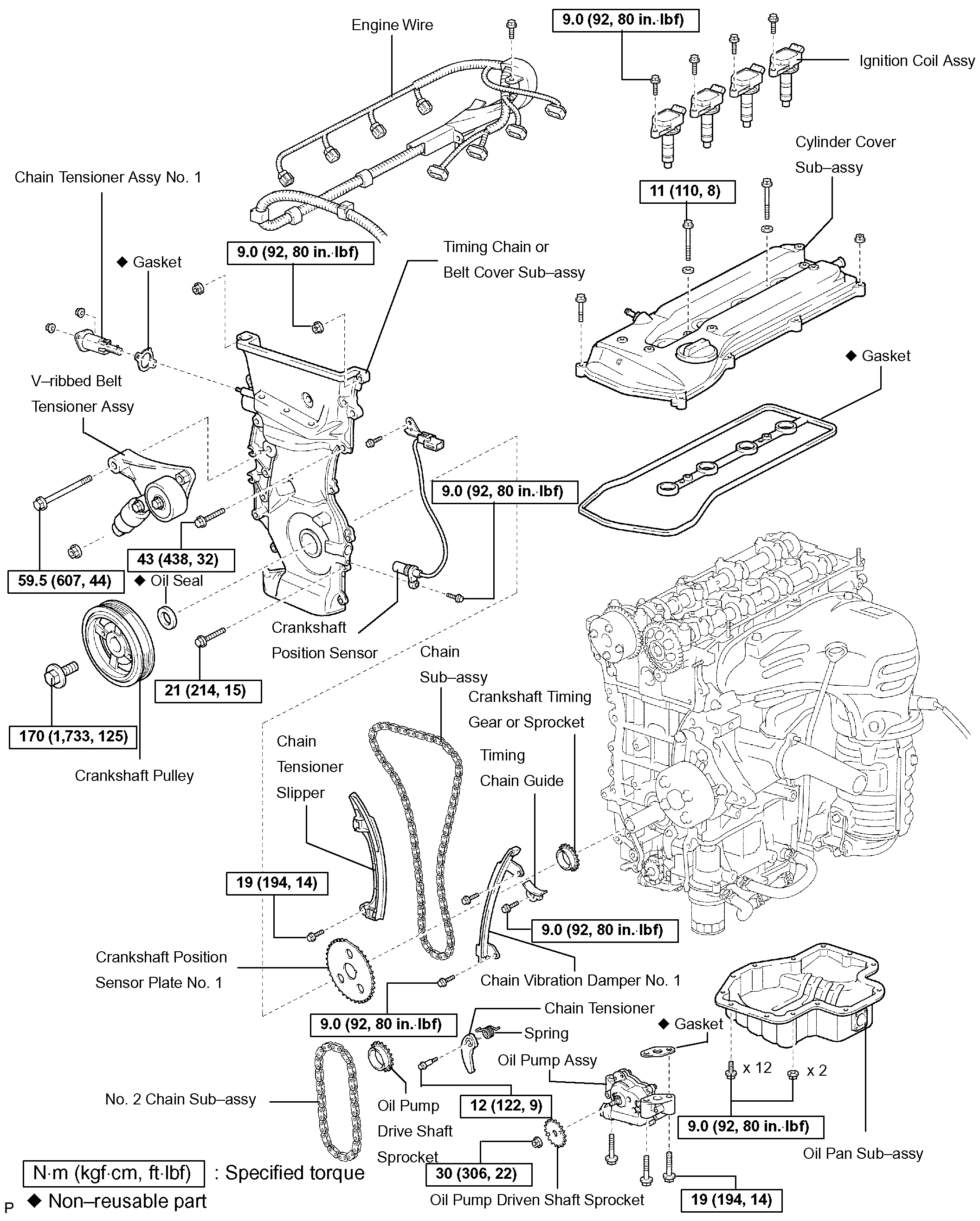
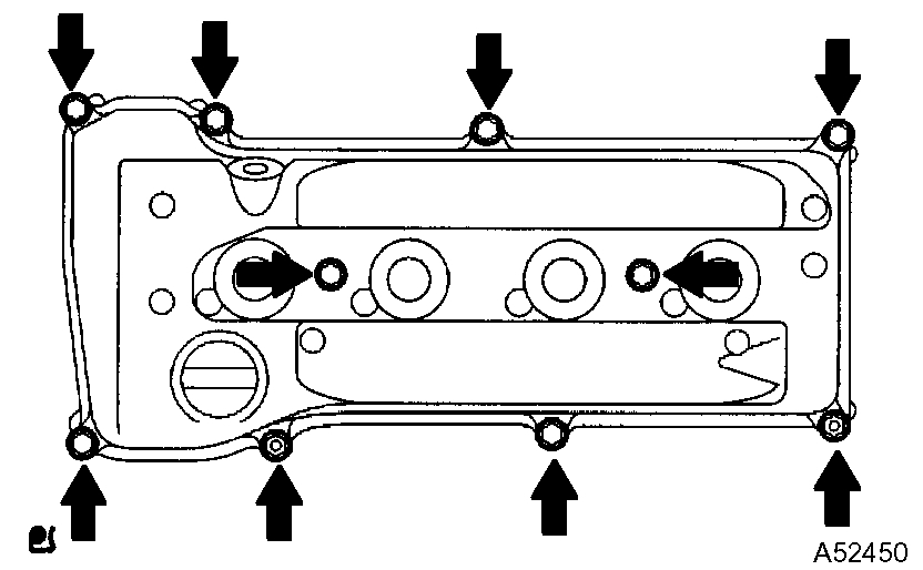
19. REMOVE CYLINDER HEAD COVER SUB-ASSY
pic 4
a) Remove the bolt and disconnect the engine wire harness clamp.
B) Remove the 8 bolts and 2 nuts, and disconnect the cylinder head cover.
20. SET NO.1 CYLINDER TO TDC/COMPRESSION
21. REMOVE CRANKSHAFT PULLEY
a) Using SST, fix the pulley and loosen the bolt.
B) Using SST, remove the bolt and pulley.
22. REMOVE CRANKSHAFT POSITION SENSOR
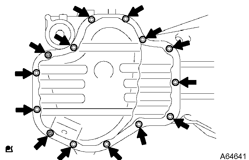
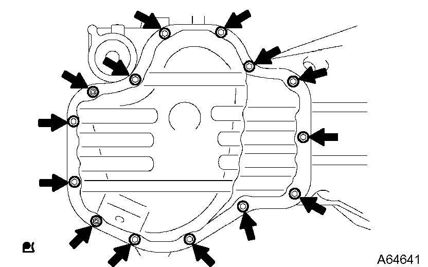
23. REMOVE OIL PAN SUB-ASSY
pic 5
a) Remove the 12 bolts and 2 nuts.
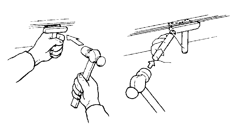
Pic 6
b) Insert the blade of SST between the crankcase and oil pan. Cut through the sealer and remove the oil pan.
SST 09032-00100
NOTICE: Be careful not to damage the contact surface of the cylinder block and oil pan.
24. REMOVE CHAIN TENSIONER ASSY NO.1
pic 7
a) Remove the 2 nuts, tensioner and gasket.
NOTICE: Do not revolve the crankshaft without the tensioner.
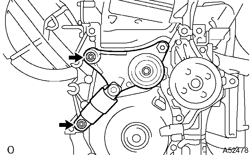
25. REMOVE V-RIBBED BELT TENSIONER ASSY
pic 8
a) Remove the bolt, nut and tensioner.
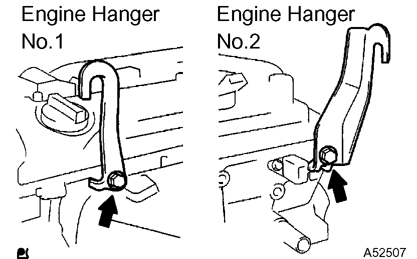
26. INSTALL ENGINE HANGER
pic 9
a) Install the engine hanger No. 1 and No. 2 with the bolts as shown in the illustration.
Pic 10
Parts No.
Torque: 38 Nm (387 kgf-cm, 28 ft. Lbs.)
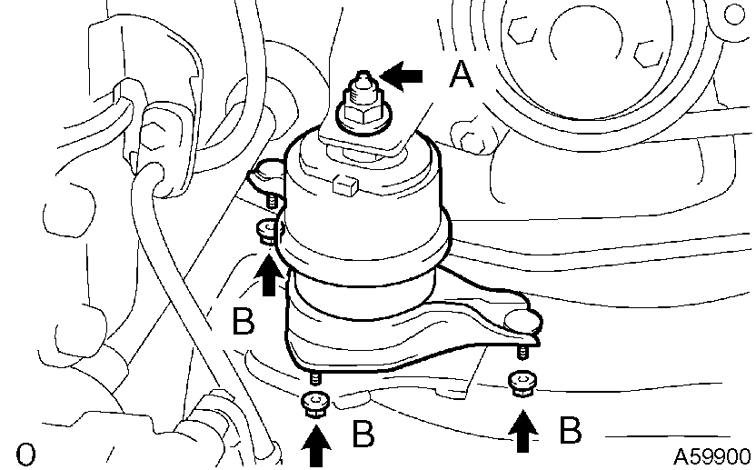
27. REMOVE ENGINE MOUNTING INSULATOR
pic 11
a) Attach the engine chain hoist to the engine hangers.
CAUTION: Do not attempt to hang the engine by hooking the chain to any other part.
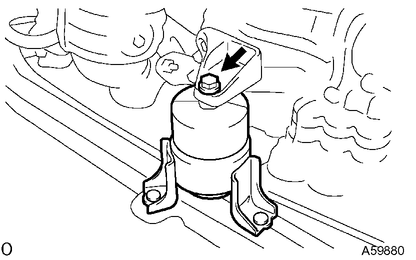
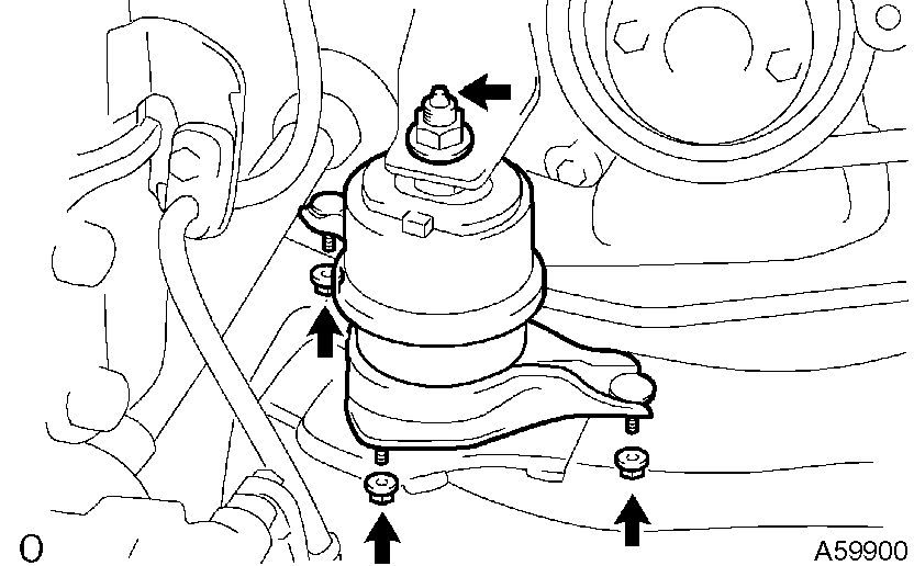
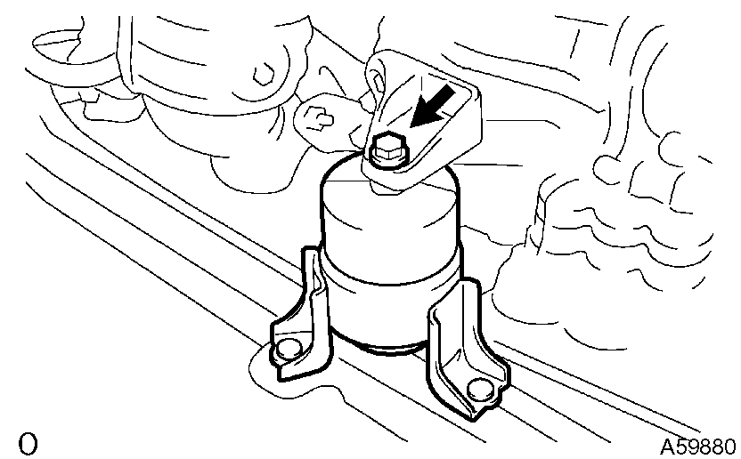
B) Remove the bolt and disconnect the engine mounting insulator FR.
Pic 12
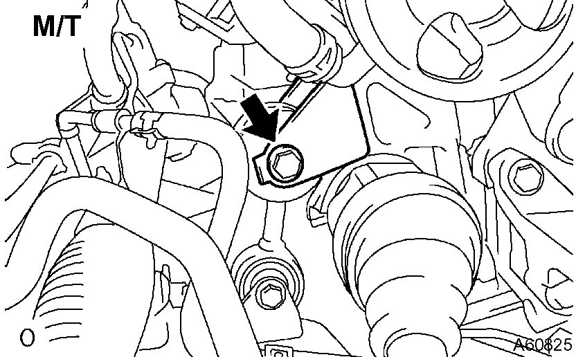
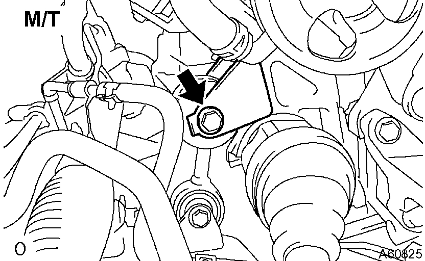
c) M/T: Remove the bolt and disconnect the engine lateral control rod.
Pic 13
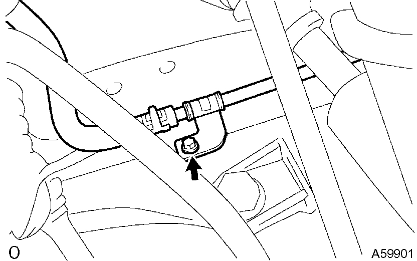
d) Remove the bolt and disconnect the steering gear return hose clamp from the frame.
Pic 14
e) Remove the 4 nuts from the engine mounting insulator RH. Raise the engine and remove the engine mounting insulator RH.
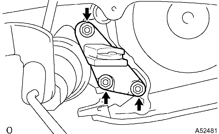
28. REMOVE ENGINE MOUNTING BRACKET RH
pic 15
a) Remove the 3 bolts and engine mounting bracket.
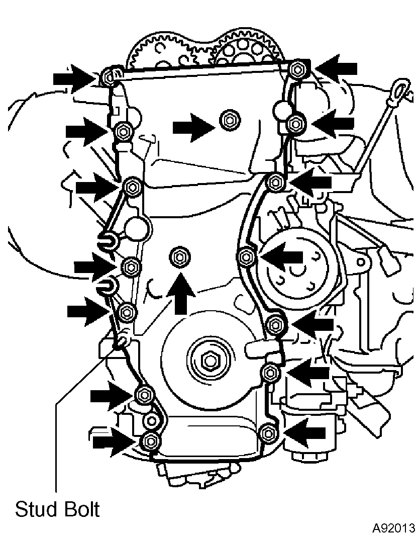
29. REMOVE TIMING CHAIN OR BELT COVER SUB-ASSY
pic 16
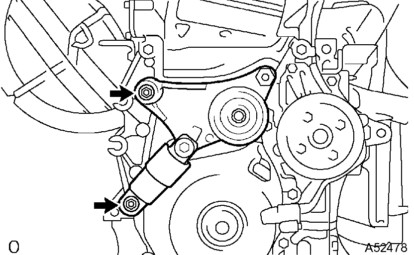
a) Remove the stud bolt for the drive belt tensioner from the cylinder block.
B) Remove the 14 bolts and 2 nuts.
C) Pry out the timing chain cover with a screwdriver.
NOTICE: Be careful not to damage the contact surfaces of the timing chain cover, cylinder block and cylinder head.
30. REMOVE CRANKSHAFT POSITION SENSOR PLATE NO.1
31. REMOVE CHAIN TENSIONER SLIPPER
32. REMOVE CHAIN VIBRATION DAMPER NO.1
33. REMOVE CHAIN SUB-ASSY
34. REMOVE CRANKSHAFT TIMING GEAR OR SPROCKET
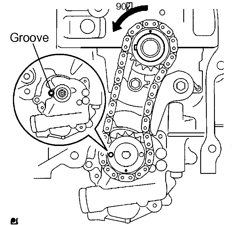
35. REMOVE NO.2 CHAIN SUB-ASSY
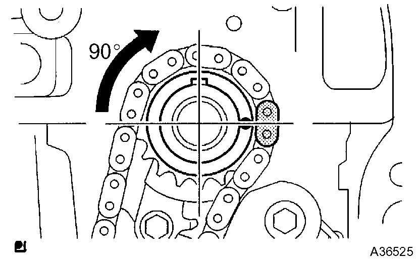
pic 17
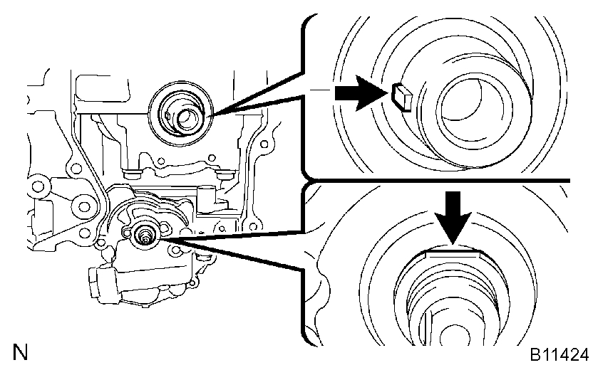
a) Turn the crankshaft counterclockwise by 90°, and align an adjusting hole of the oil pump driven sprocket with the groove of the oil pump.
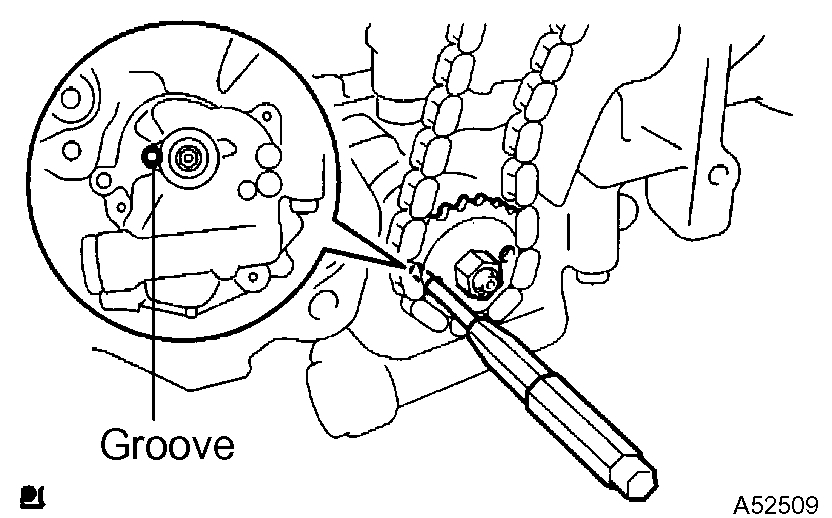
Pic 18
b) Put a bar ([diameter] 4 mm (0.16 inch)) in the adjusting hole of the oil pump driven sprocket to temporarily lock the sprocket in position. Remove the nut.
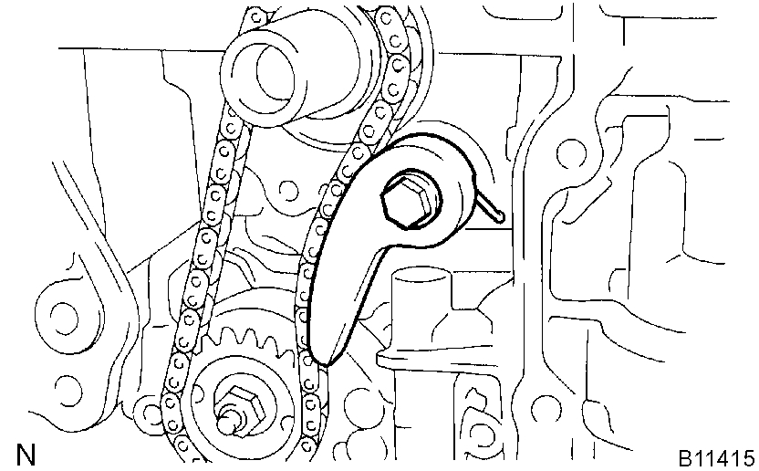
Pic 19
c) Remove the bolt, chain tensioner plate and spring.
D) Remove the chain tensioner, oil pump driven sprocket and chain.
36. INSTALL NO.2 CHAIN SUB-ASSY
pic 20
a) Set the crankshaft key into the left horizontal position.
B) Turn the cutout of the oil pump drive shaft to the top.
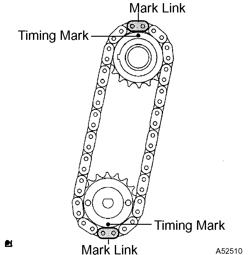
Pic 21
c) Align the mark links (yellow colored links) with the timing marks of the sprocket as shown in the illustration.
D) Insert the sprockets with chain to the crankshaft and oil pump shaft.
E) Temporarily tighten the oil pump driven sprocket with the nut.
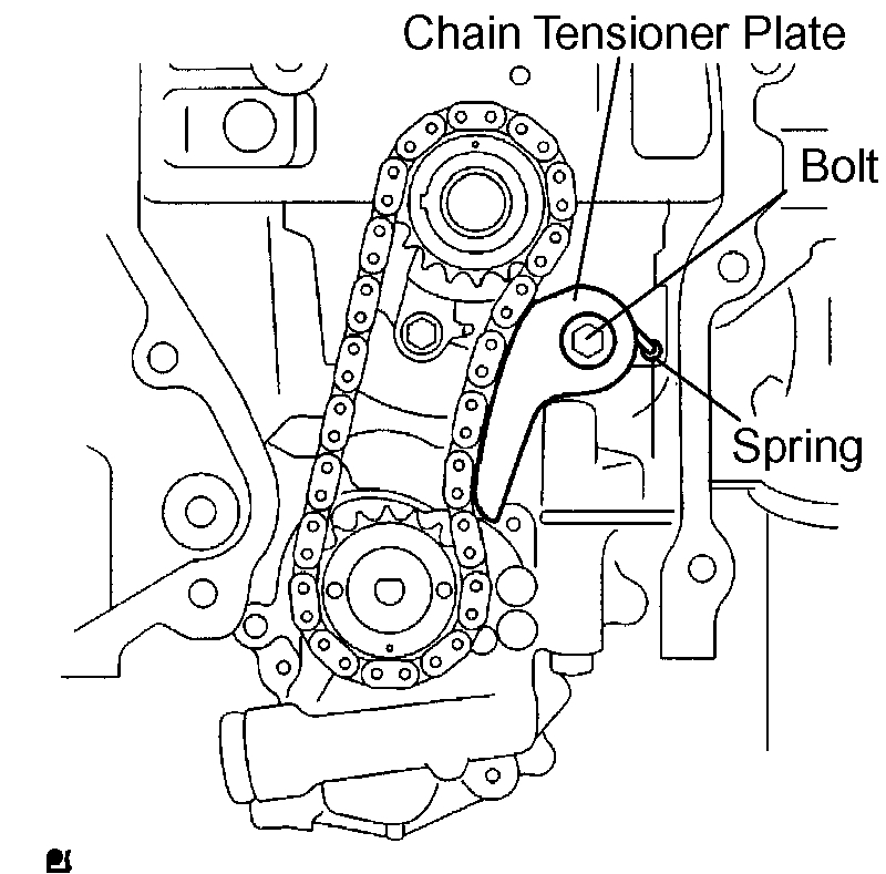
Pic 22
f) Insert the damper spring into the adjusting hole, and install the chain tensioner plate with the bolt.
Torque: 12 Nm (122 kgf-cm, 9 ft. Lbs.)
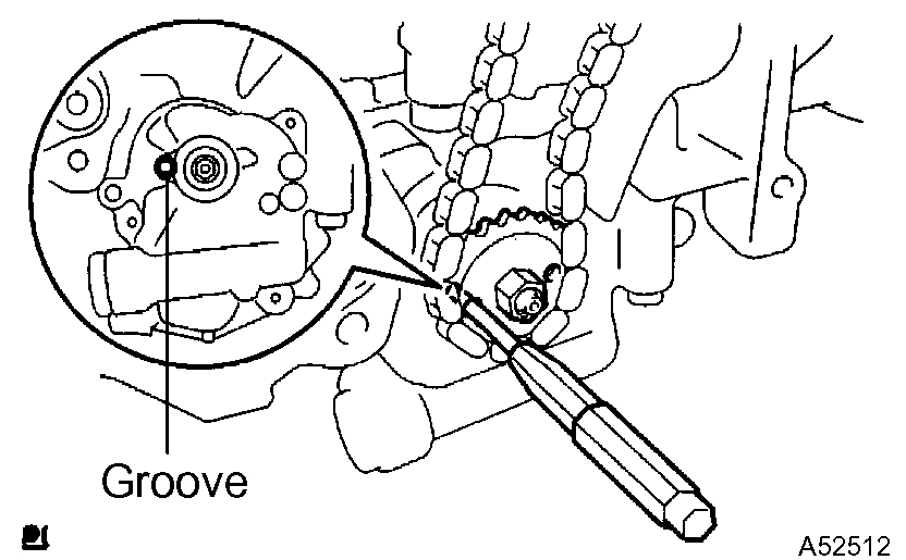
pic 23
g) Align the adjusting hole of the oil pump driven sprocket with the groove of the oil pump.
H) Put a bar ([diameter] 4 mm (0.16 inch)) in the adjusting hole of the oil pump driven sprocket to temporarily lock the sprocket in position. Install the nut.
Torque: 30 Nm (301 kgf-cm, 22 ft. Lbs.)
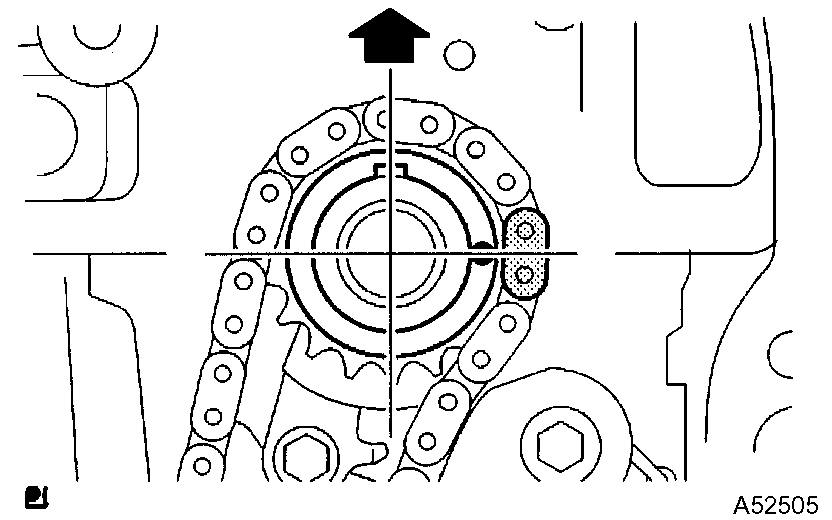
pic 24
i) Rotate the crankshaft clockwise by 90°, and align the crankshaft key to the top.
37. INSTALL CHAIN VIBRATION DAMPER NO.1
Torque: 9.0 Nm (92 kgf-cm, 80 inch lbs.)
38. INSTALL CHAIN SUB-ASSY
a) Set the No. 1 cylinder to TDC/compression.
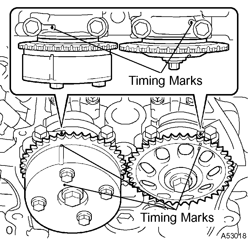
Pic 25
1) Align the timing marks of the camshaft timing gear/sprocket and bearing caps (No. 1 and No. 2).
Pic 26
2) Using the crankshaft pulley bolt, turn the crankshaft and set the set key on the crankshaft upward.
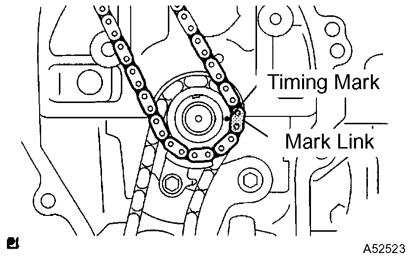
Pic 27
b) Align the mark link (gold or orange colored link) with the timing mark of the crankshaft timing sprocket.
Pic 28
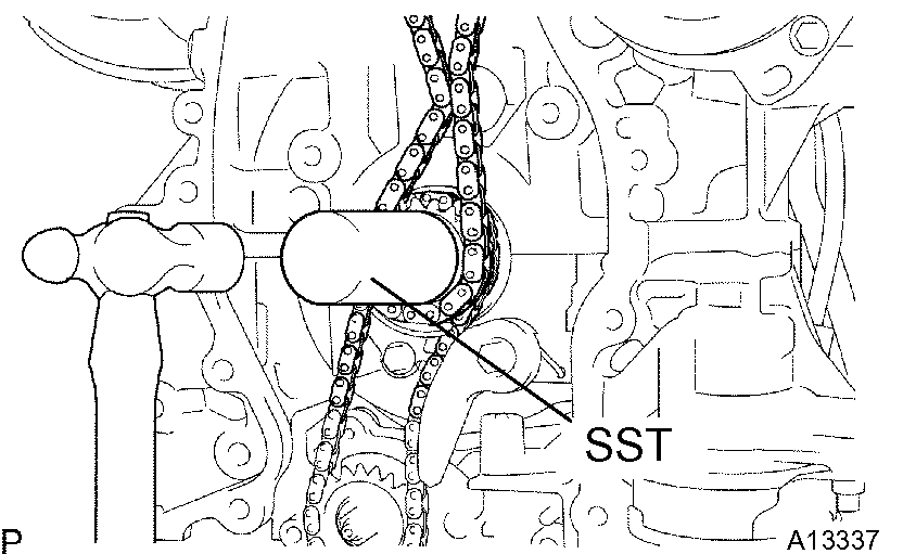
c) Using SST, tap in the sprocket.
SST 09309-37010
pic 29
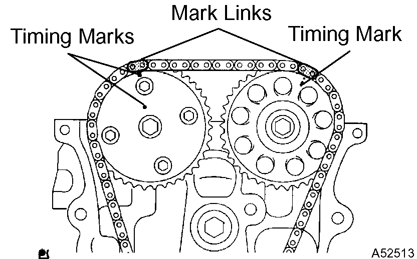
d) Align the mark links (gold or yellow colored links) with the timing marks of the camshaft timing gear and camshaft timing sprocket. Install the chain.
39. INSTALL CHAIN TENSIONER SLIPPER
Torque: 19 Nm (194 kgf-cm, 14 ft. Lbs.)
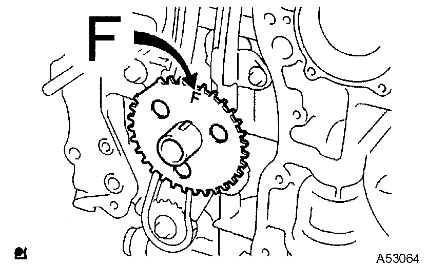
40. INSTALL CRANKSHAFT POSITION SENSOR PLATE NO.1
pic 30
a) Install the sensor plate with the F mark facing forward.
41. INSTALL TIMING CHAIN OR BELT COVER SUB-ASSY
pic 31
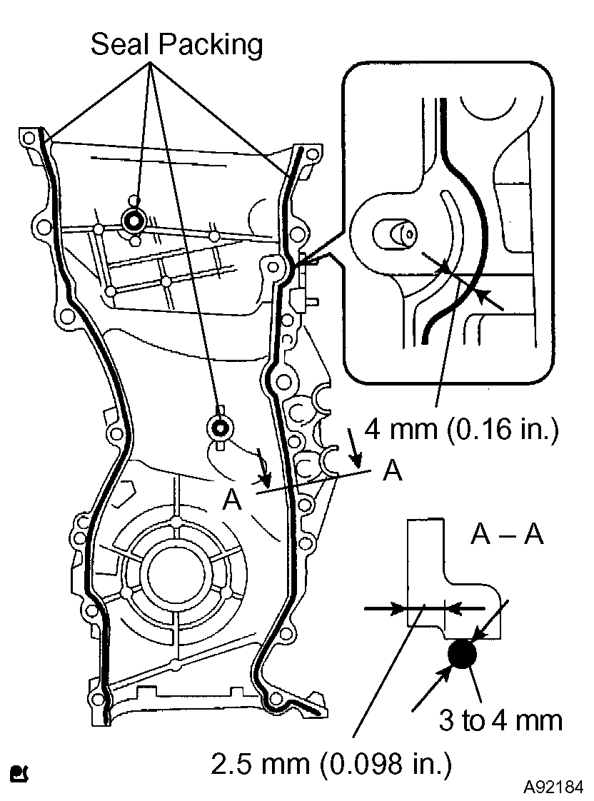
a) Remove any old packing (FIPG) material and be careful not to drop any oil on the contact surfaces of the timing chain cover, cylinder head and cylinder block.
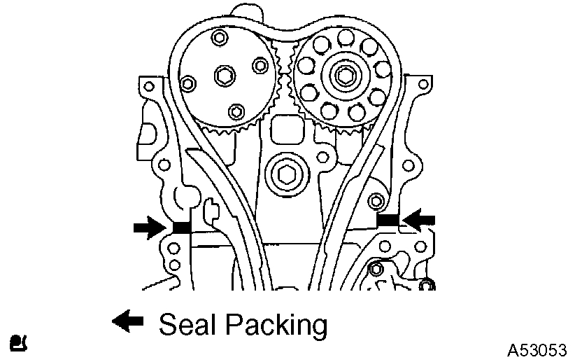
B) Apply seal packing (diameter: 2 mm (0.08 inch)) as shown in the illustration.
Seal packing: Part No. 08826-00080 or equivalent
NOTICE:
Remove any oil from the contact surface.
Install the chain cover within 3 minutes after applying seal packing.
Do not start the engine for at least 2 hours after installing.
Pic 32
c) Apply seal packing in a continuous bead (diameter: 3 to 4 mm (0.12 to 0.16 inch)) as shown in the illustration.
Seal packing: Part No. 08826-00080 or equivalent
pic 33
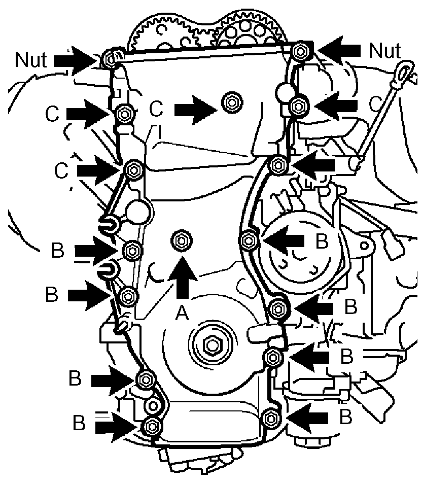
d) Install the timing chain cover with the 14 bolts and 2 nuts.
Torque:
9.0 Nm (92 kgf-cm, 80 inch lbs.) For bolt A
21 Nm (214 kgf-cm, 15 ft. Lbs.) For bolt B
43 Nm (438 kgf-cm, 32 ft. Lbs.) For bolt C
9.0 Nm (92 kgf-cm, 80 inch lbs.) For nut
e) Install the stud bolt to the drive belt tensioner.
Torque: 10 Nm (102 kgf-cm, 7 ft. Lbs.)
42. INSTALL V-RIBBED BELT TENSIONER ASSY
pic 34
a) Install the tensioner with the bolt and nut.
Torque: 59.5 Nm (607 kgf-cm, 44 ft. Lbs.)
43. INSTALL ENGINE MOUNTING BRACKET RH
pic 35
a) Install the engine mounting bracket with the 3 bolts.
Torque: 54 Nm (551 kgf-cm, 40 ft. Lbs.)
44. INSTALL ENGINE MOUNTING INSULATOR
pic 36
a) Raise the engine and install the engine mounting insulator RH.
B) Install the engine mounting insulator RH with the 4 nuts.
Torque: 95 Nm (969 kgf-cm, 70 ft. Lbs.) For nut A
87 Nm (888 kgf-cm, 64 ft. Lbs.) For nut B
pic 37
c) Install the steering gear return hose clamp to the frame with the bolt.
Torque: 8.0 Nm (80 kgf-cm, 69 inch lbs.)
pic 38
d) Install the engine mounting insulator FR with the bolt.
Torque: 87 Nm (888 kgf-cm, 64 ft. Lbs.)
pic 39
e) M/T: Install the engine lateral control rod with the bolt.
Torque: 89 Nm (910 kgf-cm, 66 ft. Lbs.)
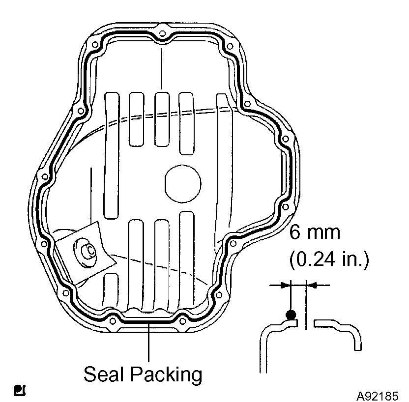
45. INSTALL OIL PAN SUB-ASSY
pic 40
a) Remove any old packing (FIPG) material and be careful not to drop any oil on the contact surface of the cylinder block and oil pan.
B) Apply seal packing in a continuous bead (diameter: 3 to 4 mm (0.12 to 0.16 inch)) as shown in the illustration, and install the oil pan.
Seal packing: Part No. 08826-00080 or equivalent
NOTICE:
Remove any oil from the contact surface.
Install the oil pan within 3 minutes after applying seal packing.
Do not start the engine for at least 2 hours after installing.
Pic 41
c) Install the oil pan with the 12 bolts and 2 nuts.
Torque: 9.0 Nm (92 kgf-cm, 80 inch lbs.)
46. INSTALL CHAIN TENSIONER ASSY NO.1
47. INSTALL CRANKSHAFT POSITION SENSOR
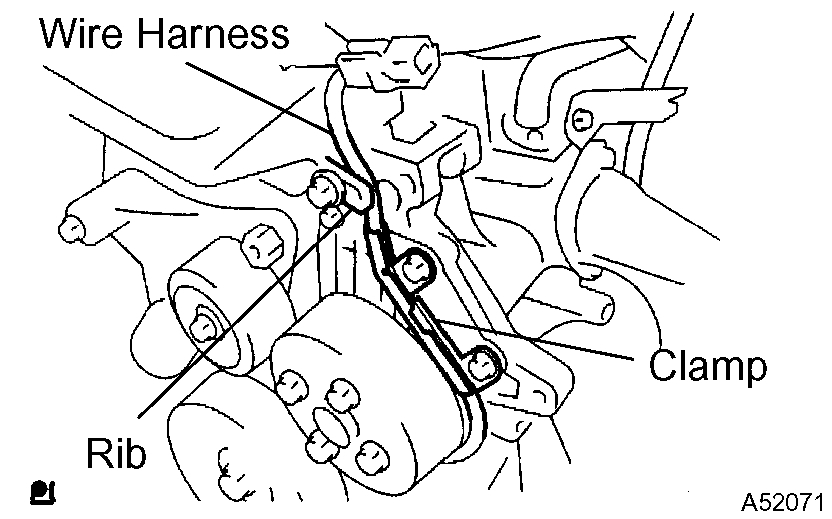
pic 42
a) Install the sensor with the bolt.
Torque: 9.0 Nm (92 kgf-cm, 80 inch lbs.)
b) Confirm that the wire harness of the sensor is placed as shown in the illustration.
48. INSTALL CRANKSHAFT PULLEY
a) Install the crankshaft pulley.
1) Align the pulley set key with the key groove of the pulley, and side on the pulley.
2) Using SST, install the pulley bolt.
Torque: 170 Nm (1,733 kgf-cm, 125 ft. Lbs.)
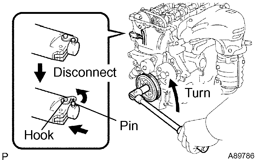
pic 43
b) Turn the crankshaft counterclockwise and disconnect the plunger knock pin from the hook.
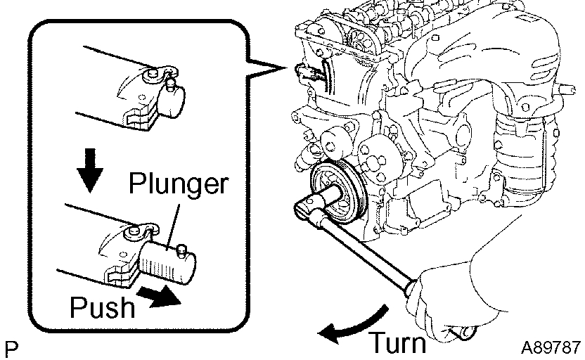
Pic 44
c) Turn the crankshaft clockwise and check that the slipper is pushed by the plunger.
49. INSTALL CYLINDER HEAD COVER SUB-ASSY
50. INSTALL IGNITION COIL ASSY
Torque: 19 Nm (194 kgf-cm, 14 ft. Lbs.)
51. INSTALL VANE PUMP ASSY
52. INSTALL GENERATOR ASSY
53. INSTALL ENGINE WIRE
54. INSTALL FAN AND GENERATOR V BELT
55. INSTALL ENGINE MOUNTING BRACKET NO.2 RH
Torque: 52 Nm (531 kgf-cm, 38 ft. Lbs.)
56. INSTALL ENGINE MOUNTING STAY NO.2 RH
Torque: 64 Nm (653 kgf-cm, 47 ft. Lbs.)
pic 45
57. INSTALL ENGINE MOVING CONTROL ROD W/BRACKET
a) Install the engine mounting control rod with the 3 bolts.
Torque: 64 Nm (653 kgf-cm, 47 ft. Lbs.)
58. INSTALL EXHAUST PIPE ASSY FRONT
59. INSTALL FRONT WHEEL RH
60. INSTALL HOOD SUB-ASSY
Torque: 13 Nm (133 kgf-cm, 10 ft. Lbs.)
61. ADD ENGINE OIL
62. CHECK FOR ENGINE OIL LEAKS
____________________________________
Let me know if that helps or if you have other questions.
Take care,
Joe
Images (Click to make bigger)
Sunday, September 13th, 2020 AT 6:13 PM