Hello,
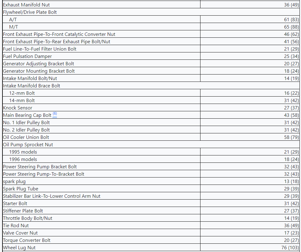
For tightening torque specifications please see images 6+7 below
TIMING BELT
REMOVAL
Disconnect negative battery cable. Raise and support vehicle. Remove lower engine cover.
Remove passenger's side front wheel and generator. Remove coolant reservoir tank. Remove accessory drive belts.
Remove spark plugs. Using floor jack, slightly raise engine to remove weight from engine mount for access to timing belt covers.
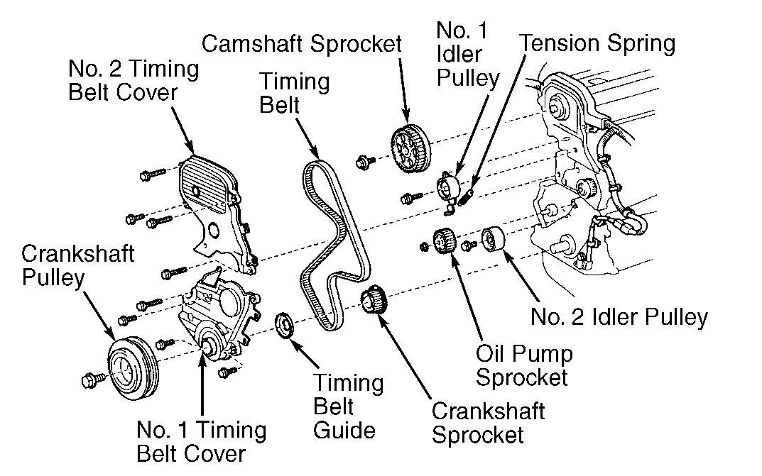
Remove engine mount and bracket from front of engine. Remove No. 2 timing belt covers and gaskets. see image 1 below.
Rotate crankshaft clockwise (viewed from timing belt end of engine) so cylinder No. 1 is at TDC on compression stroke and timing mark on crankshaft pulley aligns with "0" mark on timing belt cover. Cylinder No. 1 is the front cylinder at the timing belt end of engine.
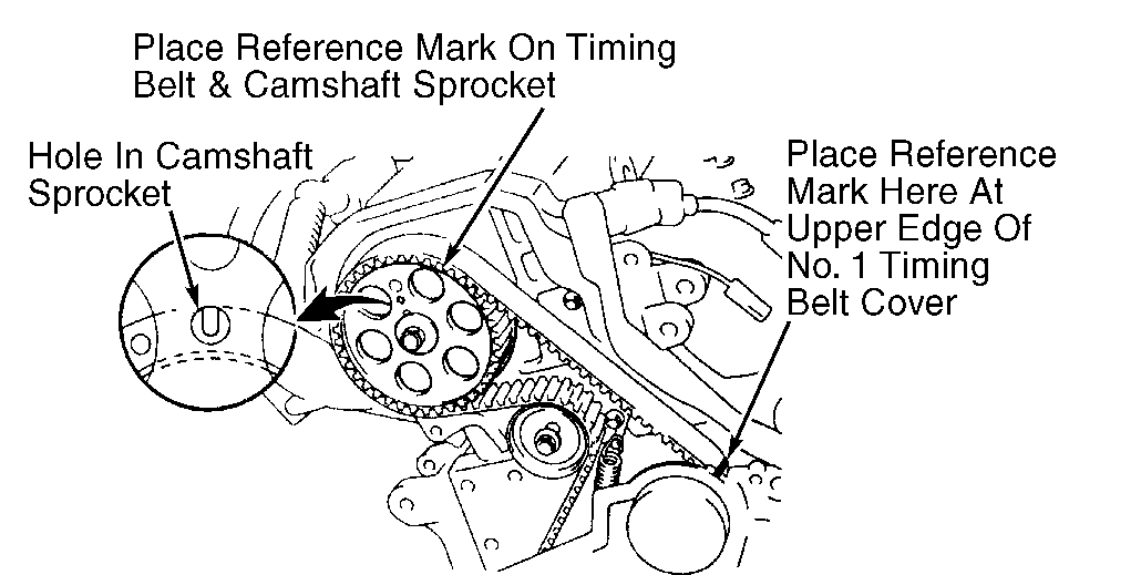
Ensure the hole in the camshaft sprocket aligns with alignment mark on camshaft bearing cap. see image 2. If the hole in camshaft sprocket is not aligned with alignment mark, rotate crankshaft clockwise one complete revolution (360 degrees).
CAUTION: If reusing timing belt, mark direction of timing belt rotation and place reference mark on timing belt at camshaft sprocket for reassembly reference. Also place reference mark on timing belt at upper edge of No. 1 timing belt cover. see image 2.
Loosen No. 1 idler pulley bolt. seeFig.15. Move No. 1 idler pulley outward, away from timing belt as far as possible. Temporarily retighten No. 1 idler pulley bolt. Remove timing belt from camshaft sprocket.
If reusing timing belt, ensure reference mark placed on timing belt aligns with upper edge of No. 1 timing belt cover when timing mark on crankshaft pulley aligns with "0" mark on No. 1 timing belt cover. If reference mark is aligned, proceed to step 14).
If reference mark is below surface of No. 1 timing belt cover, pull upward on water pump side of timing belt while rotating crankshaft pulley counterclockwise. Align reference mark with upper edge of No. 1 timing belt cover.
Hold upward on water pump side of timing belt. Rotate crankshaft pulley clockwise so timing mark on crankshaft pulley aligns with "0" mark on No. 1 timing belt cover.
If the reference mark is above the upper edge of No. 1 timing belt cover, pull upward on No. 1 idler pulley side of timing belt while rotating crankshaft pulley clockwise. Align reference mark with upper edge of No. 1 timing belt cover.
Hold upward on No. 1 idler pulley side of timing belt. Rotate crankshaft pulley counterclockwise so timing mark on crankshaft pulley aligns with "0" mark on No. 1 timing belt cover.
Remove crankshaft pulley bolt. Using puller, remove crankshaft pulley. Remove No. 1 timing belt cover and gasket. Note: direction of timing belt guide installation. see image 1. Remove timing belt guide.
If reusing timing belt, mark direction of timing belt rotation and place reference marks on timing belt and crankshaft sprocket for reassembly reference. Remove timing belt from crankshaft sprocket.
Remove idler pulleys (if necessary). If removing camshaft sprocket, use spanner wrench to hold camshaft sprocket and remove camshaft sprocket bolt. Remove camshaft sprocket.
On 1995 model, if removing crankshaft sprocket, place shop towels against oil pump housing. Using 2 screwdrivers, carefully pry sprocket from crankshaft. Use care not to damage oil pump housing.
On 1996 model, if removing crankshaft sprocket, use puller to pull crankshaft sprocket from crankshaft.
On all models, if removing oil pump sprocket, hold oil pump sprocket by installing spanner wrench in holes on front of oil pump sprocket. Remove oil pump sprocket nut. Remove spanner wrench and oil pump sprocket.
INSTALLATION
If installing oil pump sprocket, align cut-out areas on oil pump sprocket with areas on oil pump shaft. Install oil pump sprocket. Install and tighten oil pump sprocket nut to specification while holding oil pump sprocket with spanner wrench. See TORQUE SPECIFICATIONS .
If installing crankshaft sprocket, align crankshaft sprocket with key in crankshaft. Install crankshaft sprocket with flange toward cylinder block. see image 1.
Install No. 2 idler pulley (if removed). Ensure the 1.38" (35.0 mm) long bolt is used for the No. 2 idler pulley. Tighten bolt to specification. See TORQUE SPECIFICATIONS . Ensure No. 2 idler pulley is clean and rotates smoothly.
CAUTION: Pivot hole at top of No. 1 idler pulley mounting flange must engage with pin on front of cylinder block when installing No. 1 idler pulley.
Install No. 1 idler pulley and tension spring (if removed). Ensure the 1.65" (42.0 mm) long bolt is used for the No. 1 idler pulley. DO NOT tighten bolt at this time. Ensure pivot hole at top of No. 1 idler pulley mounting flange engages with pin on front of cylinder block.
Move No. 1 idler pulley away from timing belt area as far as possible. Temporarily tighten No. 1 idler pulley bolt. Ensure No. 1 idler pulley is clean and rotates smoothly.
If installing camshaft sprocket, align pin groove in camshaft sprocket with pin in camshaft. Install camshaft sprocket. Install and tighten camshaft sprocket bolt to specification. See TORQUE SPECIFICATIONS .
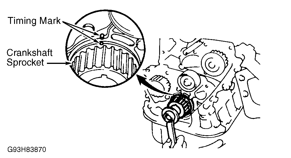
Using crankshaft pulley bolt, rotate crankshaft so key on crankshaft is at 12 o'clock position and timing mark (if equipped) on crankshaft sprocket aligns with timing mark on oil pump housing. see image 8.
CAUTION: If reusing timing belt, ensure reference mark on timing belt aligns with reference mark placed on crankshaft sprocket and timing belt is installed in original direction of rotation.
Ensure all sprockets and idler pulleys are clean. Install timing belt on crankshaft sprocket, oil pump sprocket, water pump sprocket, No. 1 idler pulley, and then No. 2 idler pulley.
Install timing belt guide with cupped side away from crankshaft sprocket and flat side toward timing belt. Install No. 1 timing belt cover and gasket.
Remove crankshaft pulley bolt from crankshaft. Align groove in crankshaft pulley with key in crankshaft. Install crankshaft pulley. Install and tighten crankshaft pulley bolt to specification. See TORQUE SPECIFICATIONS .
Rotate crankshaft clockwise so cylinder No. 1 is at TDC on compression stroke and timing mark on crankshaft pulley aligns with "0" mark on No. 1 timing belt cover. Rotate camshaft and align hole in camshaft sprocket with alignment mark on camshaft bearing cap. seeFig.16.
If reusing timing belt, ensure reference mark on timing belt aligns with upper edge of No. 1 timing belt cover. If reference mark is not aligned, perform procedure in steps 10) through 13) under removal procedure.
Install timing belt on camshaft sprocket. If reusing timing belt, ensure reference mark on timing belt aligns with reference mark placed on camshaft sprocket. Ensure tension exists on timing belt between crankshaft and camshaft sprockets.
Loosen No. 1 idler pulley bolt 1/2 turn. Rotate crankshaft pulley clockwise 2 complete revolutions from TDC to TDC. DO NOT rotate crankshaft counter clockwise.
Ensure timing mark on crankshaft pulley aligns with "0" mark on No. 1 timing belt cover and hole in camshaft sprocket aligns with alignment mark on camshaft bearing cap. seeFig.16. If timing marks are not aligned, remove timing belt and reinstall.
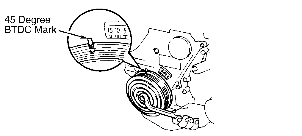
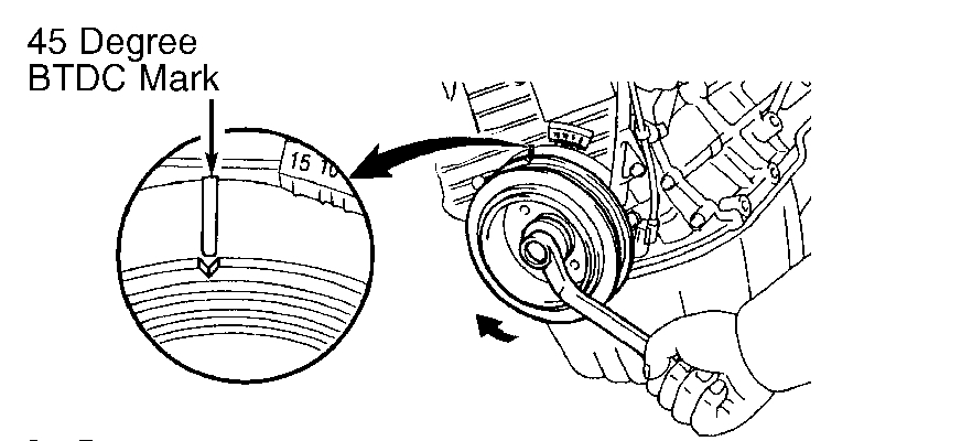
Rotate crankshaft clockwise 1 7/8 revolutions and align timing mark on crankshaft pulley with 45-degree Before Top Dead Centre (BTDC) mark on No. 1 timing belt cover. seeFig.16.
Fig. 18: Aligning Crankshaft Pulley With 45-Degree BTDC Mark (1995) see image 3
Fig. 19: Aligning Crankshaft Pulley With 45-Degree BTDC Mark (1996) see image 4
Tighten No. 1 idler pulley bolt to specification. See TORQUE SPECIFICATIONS . Install No. 2 timing belt cover and gaskets. Install and tighten spark plugs to specification. See TORQUE SPECIFICATIONS .
To install remaining components, reverse removal procedure. Install all bolts/nuts on engine mount before tightening to specification. See TORQUE SPECIFICATIONS .
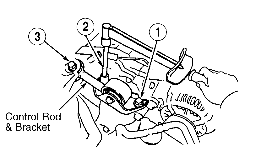
When installing control rod and bracket on strut tower and right (timing belt side) engine mount, tighten bolts to specification in sequence. see image 5
Cheers, Boris
Images (Click to enlarge)
Sep 12, 2022 at 2:25 AM