Hi and thanks for using 2CarPros.
When you say no brakes, does the pedal go to the floor? Was everything bled properly including the new master cylinder? I am going to add directions for replacing a master cylinder. I want you to confirm you did it correctly.
Here is a link that shows in general how it is done:
https://www.2carpros.com/articles/how-to-replace-a-brake-master-cylinder
Now, what I believe has happened was the push rod wasn't properly adjusted before install. Here are the directions specific to your vehicle for master cylinder replacement. The directions include adjusting. All attached pictures correlate with these directions.
___________________________________________
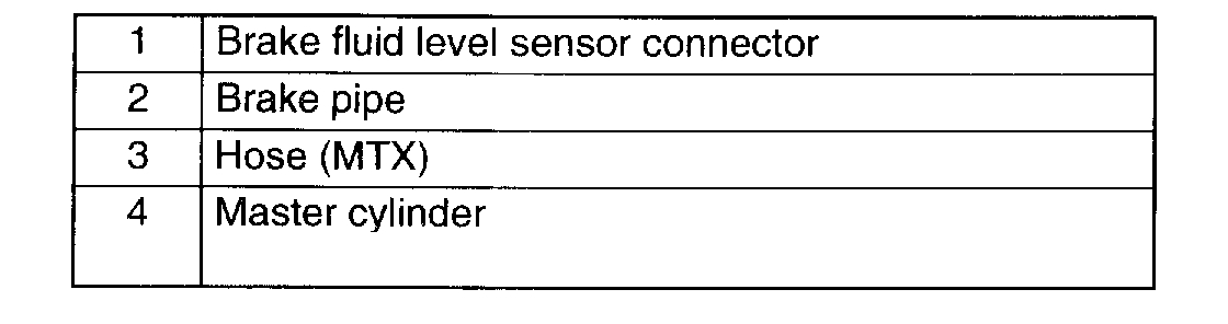
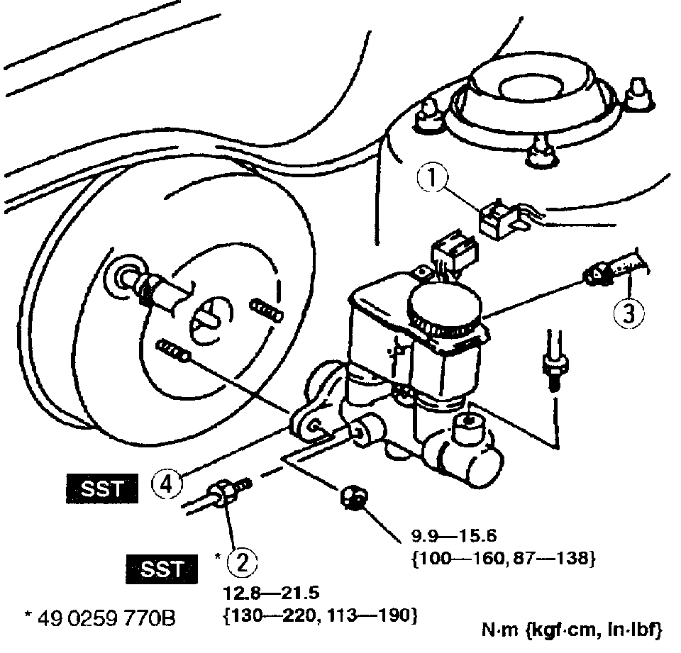
MASTER CYLINDER REMOVAL/INSTALLATION
Picture 1
1 of 2
Picture 2
2 of 2
1. Remove in the order indicated in the table.
2. Install in the reverse order of removal.
Master Cylinder Installation Note
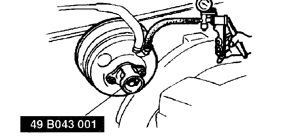
1. Turn the nut of the SST clockwise to fully retract the SST gauge rod. Attach the SST to the power brake unit.
Tightening torque 9.9 - 15 Nm (1.0 - 1.6 kgf-m, 7.3 - 11 ft. lbs.)
Picture 3
2. Apply a 66.7 kPa (500 mm Hg, 19.7 in Hg) vacuum by using a vacuum pump.
Picture 4
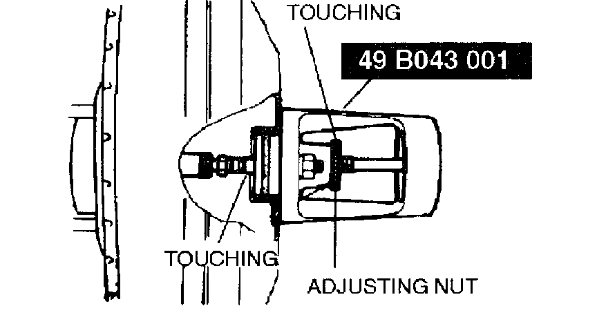
3. Turn the adjusting nut of the SST counterclockwise until the gauge rod just contacts the push rod end of the power brake unit. Push lightly on the end of the gauge rod to be sure it is seated. Verify that there is no gap between the adjusting nut and SST body.
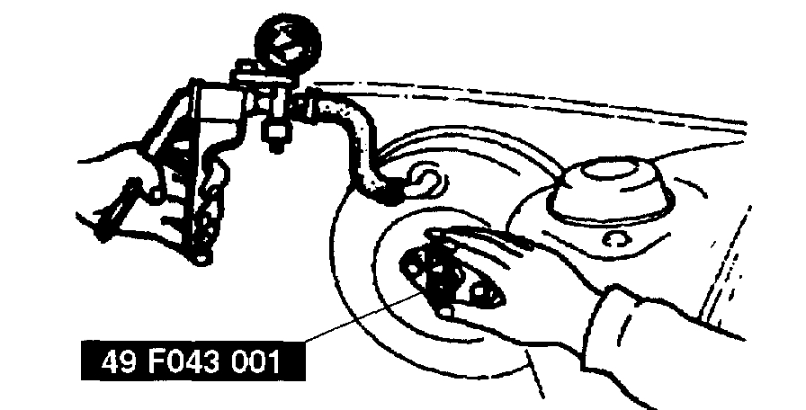
4. Remove the SST from the power brake unit without disturbing the adjusting nut. Set the SST onto the master cylinder as shown in the figure.
Caution:
When pushing the SST gauge rod into the master cylinder piston, only use enough pressure to push the rod to the bottom of the piston. If too much pressure is applied, a false reading will occur.
Picture 5
1 of 2
Picture 6
2 of 2
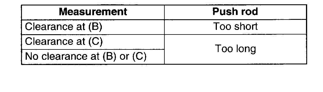
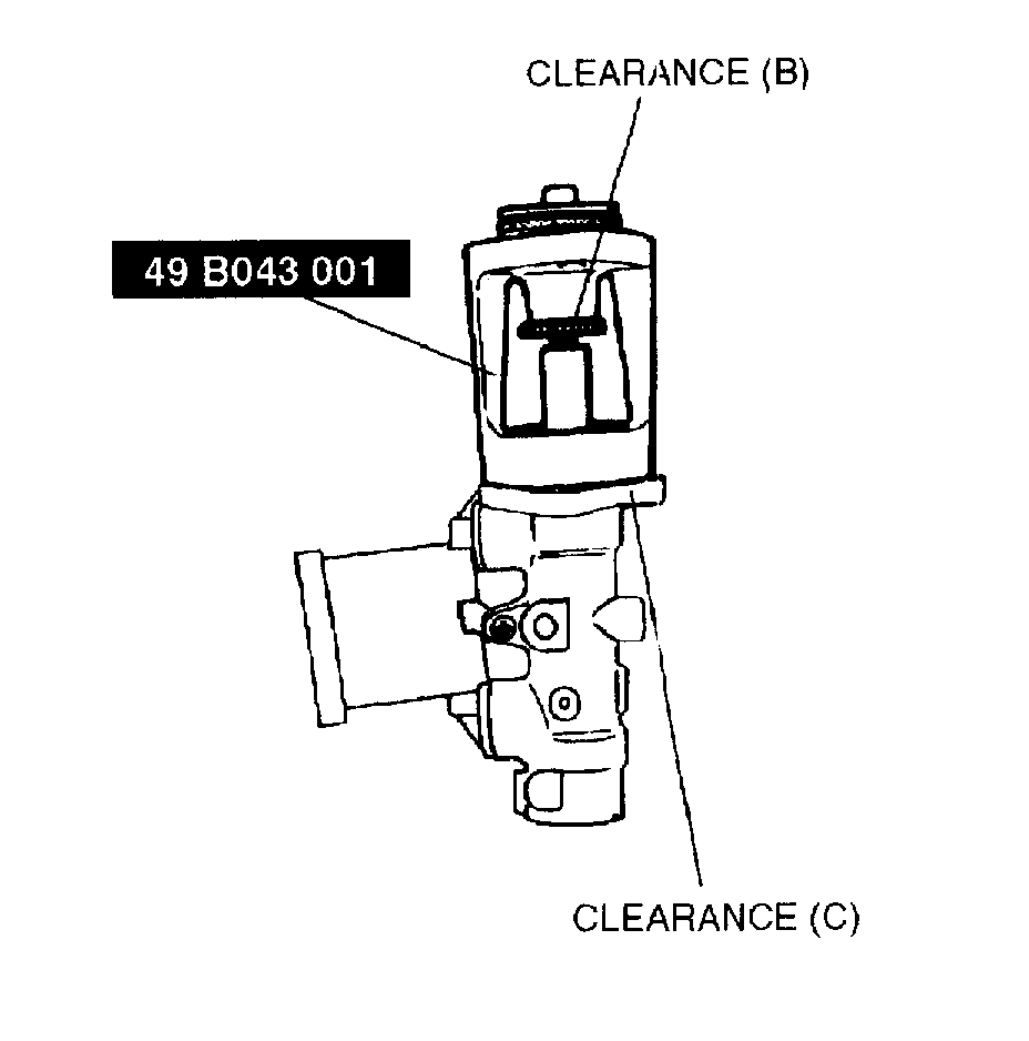
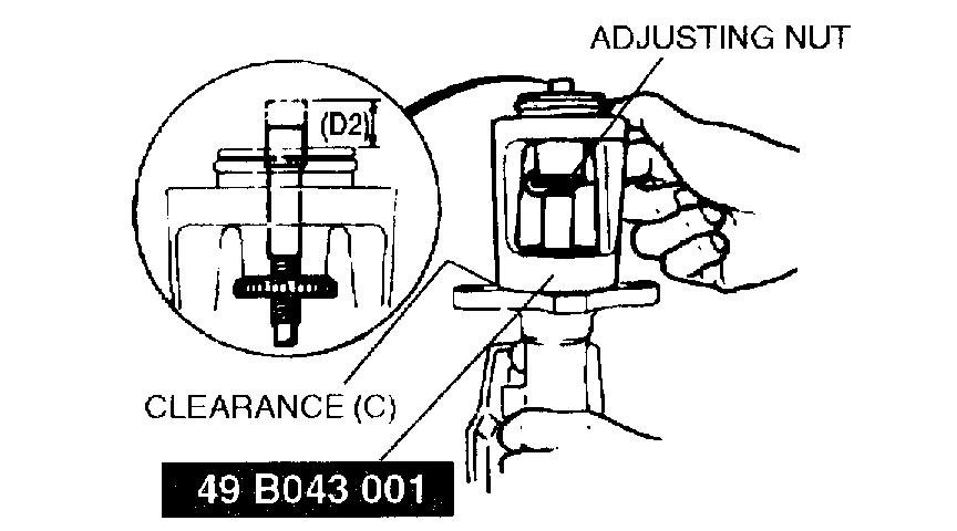
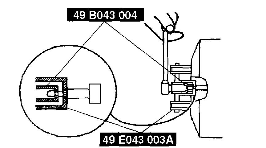
5. Push lightly on the end of the SST gauge rod to be sure it has contacted the bottom of the master cylinder piston, but do not push so hard that the piston moves. Note any clearance between the SST body and the adjusting nut (clearance B) or between the body and the master cylinder (clearance C).
Adjusting the push rod clearance at B
Note:
The threads of the push rod are specially designed so that the bolt becomes harder to turn past a certain point. This is to prevent the bolt from coming loose. Turn the bolt only within this range when adjusting.
Picture 7
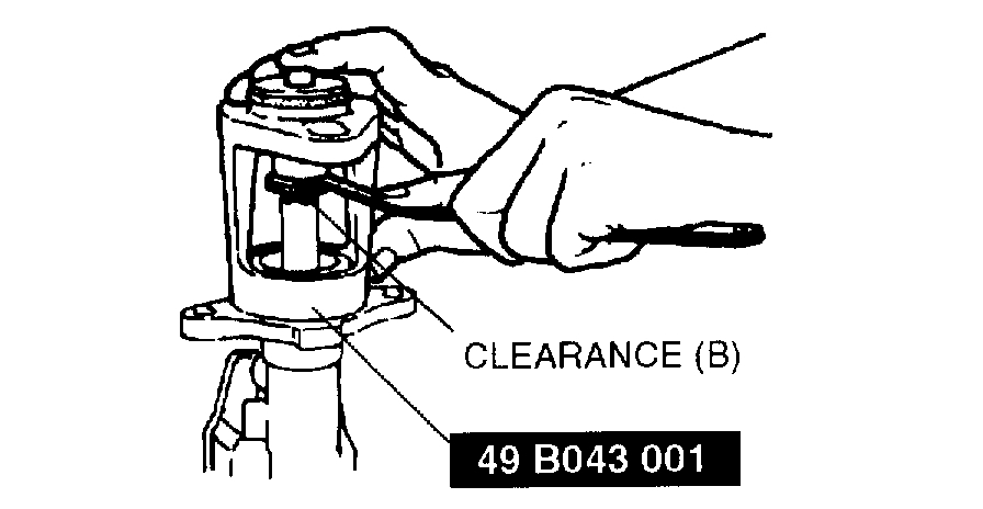
1. Push lightly on the end of the SST gauge rod, and measure the clearance between the adjusting nut and the SST body.
Picture 8
2. Using the SST, turn the nut to lengthen the power brake unit push rod an amount equal to the sum subtracting 0.1 - 0.4 mm (0.004 - 0.016 inch) from the clearance measured at B.
Adjusting the push rod clearance at C or no clearance at B or C
Note:
The threads of the push rod are specially designed so that the bolt becomes harder to turn past a certain point. This is to prevent the bolt from coming loose. Turn the bolt only within this range when adjusting.
Picture 9
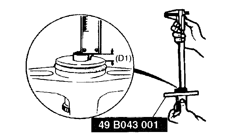
1. Measure and record height D1 of the gauge rod.
2. Turn the adjusting nut until the SST body sets evenly on the master cylinder. (Turn only enough for the body to touch.)
Picture 10
3. Measure and record height D2 of the gauge rod.
Picture 11
4. Subtract D1 from D2 and add 0.1 - 0.4 mm (0.004 - 0.016 inch). Using the SST, turn the nut to shorten the power booster push rod an amount equal to the sum.
Picture 12
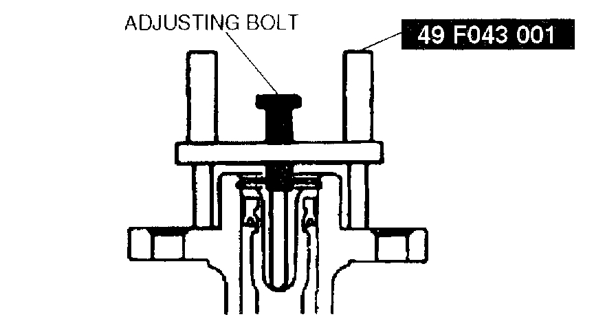
1. Place the SST atop the master cylinder. Turn the adjusting bolt until it touches the bottom of the push rod hole in the piston.
Picture 13
2. Apply 66.7 kPa (500 mm Hg, 19.7 in Hg) vacuum to the power brake unit using a vacuum pump.
Picture 14
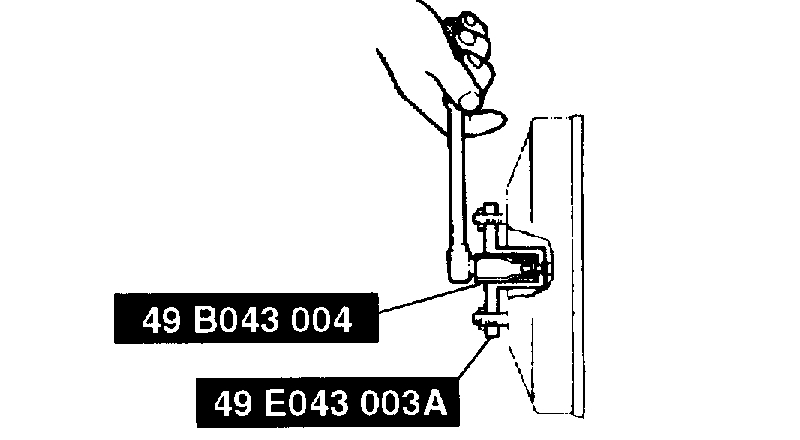
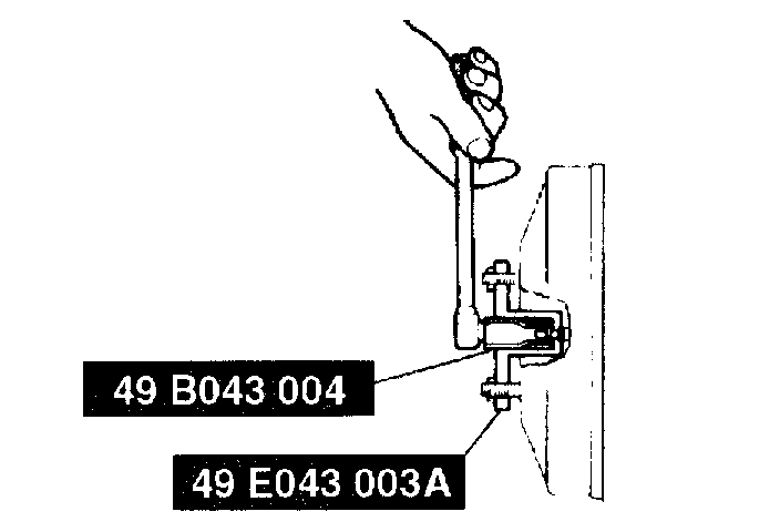
3. Invert the SST used in Step 1 and place it on the power brake unit.
4. Measure the clearance between the end of the SST and the push rod of the power brake unit.
If it is not 0.1 - 0.4 mm (0.004 - 0.016 inch), loosen the push rod lock-nut and turn the push rod to adjust it using the SSTs.
______________________________
Let me know if this helps or if you have other questions.
Take care,
Joe
Images (Click to make bigger)
Wednesday, March 13th, 2019 AT 8:16 PM