Wonderful. The maximum current the generator's field circuit can draw is close to 3.0 amps. That's with the engine running and system voltage up to 14.5 volts. At 12.6 volts with the engine off, current flow through the field circuit will be a little lower. Factor in the normal resistance in the wires, and 2.4 amps is exactly what we'd expect to see for that drain. The reason your current drops a little is likely due to other computers timing out and turning off. On newer vehicles that can be as much as three amps that takes up to 20 minutes to go to "sleep" mode.
The first thing you should do, with the ignition switch off, is to check that the "Battery" light on the dash is not on. If it is, one section of the ignition switch is melted and staying on, and that will keep the voltage regulator on. If that light is not on, continue on.
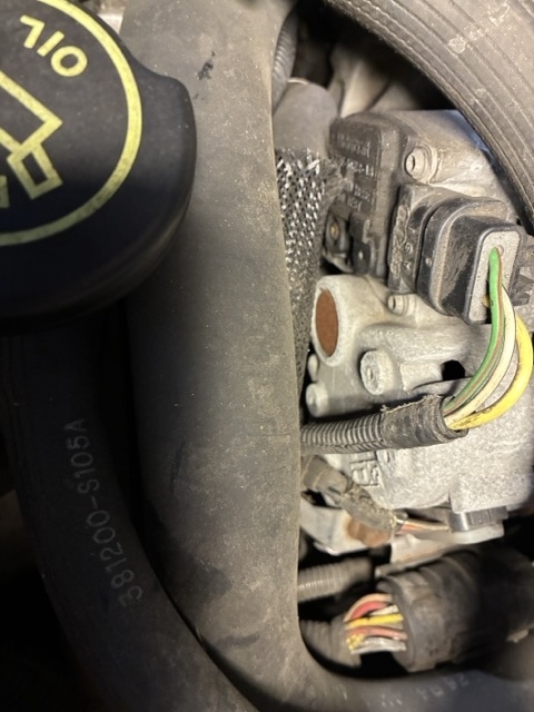
The circuit in question is the yellow / white wire in that three-wire plug. That is tied directly to battery voltage all the time, but current flow is supposed to be blocked by the voltage regulator. (That's what's not happening now). Normal operation is to turn the ignition switch to "run", then current flows through the dash "Battery" warning light, then down through the green / red wire in the three-wire plug. Roughly ten volts is dropped across the bulb to light it up, leaving about 2.5 volts at the plug. If you'd care to measure that, it must be done with the connector plugged in. You reach the terminal with the voltmeter's probe by poking it through the rubber weather seal around that wire.
The 2.5 volts on the green / red wire is what wakes up the voltage regulator and causes it to turn on. At that point current flows through the yellow / white wire, the rotating field winding, (rotor), the voltage regulator circuitry, then to ground and back to the battery.
I must add a note here; to generate a voltage mechanically, you need three things, a coil of wire, a magnetic field, and most importantly, movement between them. That why we spin the rotor with a pulley and belt. The magnetic field is an electromagnet because it is easily adjustable to adjust its strength, and therefore control the charging voltage and output current to meet the needs of the electrical system.
The last step is when the generator develops output voltage and current, a sample of that comes out on the white / black wire which also goes into the regulator. That tells the regulator the system is working. In response, the regulator puts full system voltage back out on the green / red wire. Now full voltage is on both sides of the "Battery" light. The difference is 0.0 volts, so the warning light turns off.
With this design, charging continues until the movement stops, meaning the engine stopped running. At that time, the regulator switches off the field current on the yellow / white wire. That's what's not happening.
This photo below shows the back of the generator on a Tempo that I built in "bugs" for my students to diagnose. Yours should look the same, but you may need to remove the generator from the engine. On Tempos, the regulator could be replaced without removing the generator. The engineers must have figured out this was too easy, so by the late '90s models they added a stamped tin cover to the back of the generator to be sure it was more difficult to work on.
For future reference, when you have a no-charge condition, one of the potential suspects is a failed regulator. You can bypass it by using a piece of wire or stretched-out paper clip to ground the test point my blue arrow is pointing to. You'll need to scratch around a little to break through any corrosion, and of course, this has to be done with the engine running. Turn the headlights on or connect a voltmeter to the battery to indicate system voltage. When you ground the test point to bypass a failed regulator, the lights will get noticeably brighter, and battery voltage will rise from around 12.6 volts to over 15.0 volts. Don't raise engine speed during this test as it is possible for system voltage to go high enough to damage computers and burn out any bulbs that are turned on.
Another common failure on all brands and models is worn brushes that pass the current to the spinning field winding. On this design, the brushes are bolted right to the voltage regulator, so you get new brushes with the new regulator. Once you can get to the back of the generator, remove the four torx screws in the four corners of the regulator. The "Ground here to test" screw, (blue arrow), and its mate on the other side don't get touched for this service. It's the other four, in the corners, you must remove, then the regulator pulls straight out.
The new regulator will come with a small wooden stick in the hole with the red arrow. Don't pull that stick out, . . . yet. Bolt on the new regulator, then spin the pulley to be sure nothing is binding or hitting, THEN it's okay to remove the stick. It can stick a little. You might need a needle nose pliers to pull it out. As you do, you'll hear two light clicks as the spring-loaded brushes snap into place. If the regulator is removed now, those brushes must be reloaded into their holder before reinstalling the regulator.
Thank you for posting the photos. The first one is the one not shown in the online service manuals.
May 13, 2025 at 5:19 PM