Alternator and charge light both not working

Tiny
QFONG
  • MEMBER
  • 1995 MERCURY MYSTIQUE
  • 2.5L
  • V6
  • 2WD
  • AUTOMATIC
  • 131,000 MILES
As you know on the V6 the alternator is very hard to get at. I would like to locate the green/black wire and find it's physical route to the check engine light. I think the wire might be broken.
Thursday, December 17th, 2020 AT 7:42 PM

48 Replies

Tiny
CARADIODOC
  • MECHANIC
  • 33,743 POSTS
Did you mean to say, "Battery" warning light? To save you some time, if the "Battery" light turns on when you turn the ignition switch to "run", that green / black wire is okay. If you can get to the plug on the back of the generator, and back-probe that wire, you should find around 2.0 volts. If you have to unplug it to take the reading, you'll find full battery voltage, but that is not a valid reading. In that situation, you could have a corroded connector terminal or some other break in the wire, but all it would take is enough corrosion or carbon track for enough current to get through that the meter would see that as 12 volts.

That current through the "Battery" light and green / black wire is the "turn-on" signal for the voltage regulator to turn on. At that point it starts passing current from the smaller red wire, (red arrow), through the regulator, to the "A" terminal / field coil, through the field coil to make the magnetic field, to the "F" terminal and another terminal on the regulator. From there, the regulator controls the amount of current on that circuit, then it goes to ground.

On most Ford models, that red wire is fused with a 10 or a 15-amp fuse, and it is a real common cause of no-charge problems. There's no fuse shown here, so that's one less thing to look for.

Once the system starts charging, half of charging voltage shows up on the gray wire. That also goes to the regulator. That is what tells it the desired output is occurring. At that point, the regulator puts full system voltage back out on the green / black wire. With full system voltage on both sides of the "Battery" light, the difference is 0 volts, so the bulb turns off.

Besides turning the warning light on when the system isn't charging, this regulator is also capable of turning it on when it sees an overcharge condition.

There's two ways to start the diagnosis. If you can reach the connector on the back of the generator, take the voltage reading on the smaller red wire. It should be full battery voltage all the time. If it's missing, check on the large output stud on the back of the generator. If you find 0 volts there, the generator likely has a pair of shorted diodes, and the 175-amp maxi fuse is blown. That fuse also commonly blows when a wrench slips and shorts that terminal to ground.

The other test involves finding the "F" terminal and grounding that with a jumper wire. Four screws hold the regulator to the back of the generator, then there's two more screws for the "A" and "F" terminals. The "F" terminal has the blue arrow pointing to it in the second drawing. The engine needs to be running during this test. Grounding the "F" terminal bypasses the regulator and puts full system voltage across the field coil. If everything else is okay, the generator will start to charge wide-open. Do not raise engine speed during that test because charging voltage could go as high as 18 - 20 volts or more. The battery is the only thing holding voltage down to a somewhat safe level. If this works, the regulator can be replaced separately, often without removing the generator from the engine.
Was this
answer
helpful?
Yes
No
+1
Friday, December 18th, 2020 AT 1:27 PM
Tiny
QFONG
  • MEMBER
  • 92 POSTS
The problem is that on the Mystique V6 the generator and the voltage regulator are under the engine and cannot be accessed without disassembling a few parts around the bottom of the engine. I was hoping to be able to find the green/black wire downstream somewhere that it can be accessed but I cannot see where it leaves the regulator and where it runs to. I can find a small gauge green/black wire under the dash that has some voltage but cannot trace it back to the generator. I do not want do it but it looks like I'll have to remove the gen unless you guys have any other ideas.
Was this
answer
helpful?
Yes
No
Friday, December 18th, 2020 AT 3:48 PM
Tiny
CARADIODOC
  • MECHANIC
  • 33,743 POSTS
I overlooked that you already posted the warning light isn't working. That would mean you were on the right track with the green / black wire. First check the 7.5-amp fuse that feeds that circuit. For the benefit of others researching this topic, the only information about the inside fuse box location is, "The fuse junction panel is located to left of steering column and is attached to the instrument panel.".

The second drawing shows the fuse box layout, but they used different designations between that drawing and the wiring diagram. You'll have to check all the 7.5-amp fuses.

https://www.2carpros.com/articles/how-to-check-a-car-fuse

After that fuse, the warning light bulb comes next. Even if that is burned out, there is always a resistor in parallel with it to get the charging system started. In that case, the only symptom would be the lack of the warning light turning on when the ignition switch is turned to "run".

Next, there's two connectors in the green / black wire. They're pointed out with the purple and blue arrows. There's no drawing to show the locations. They're listed as:

C206 Under LH side of I/P, above interior fuse panel
C100 LH side of engine compartment, near strut tower

C100 sounds like a good place to find the green / black wire. If you can find that, tell me what you find for voltage there. Here again it will be more accurate if taken with the plug connected.
Was this
answer
helpful?
Yes
No
+1
Friday, December 18th, 2020 AT 5:33 PM
Tiny
QFONG
  • MEMBER
  • 92 POSTS
Thanks, I'll go back to work on it Saturday. I know it's not charging because the small temporary battery I was using went low.
Was this
answer
helpful?
Yes
No
Friday, December 18th, 2020 AT 7:15 PM
Tiny
CARADIODOC
  • MECHANIC
  • 33,743 POSTS
Please keep me updated on your progress.
Was this
answer
helpful?
Yes
No
+1
Saturday, December 19th, 2020 AT 3:08 PM
Tiny
QFONG
  • MEMBER
  • 92 POSTS
I found C100 connector, unplugged it and exposed the wires and watched the wire covering turn to dust. I did spot the green/black wire but before I go any further, I'll have to re-insulate the wires. I've done this before replacing all the wiring from the PCM connector to all the sensors, ignition module, IACV, etc. After that the engine started and ran well but no battery charging.
Was this
answer
helpful?
Yes
No
Saturday, December 19th, 2020 AT 7:16 PM
Tiny
QFONG
  • MEMBER
  • 92 POSTS
Today I worked on re-insulating the C100 wires but only got about half of them done. It's a slow process to do it right.
Was this
answer
helpful?
Yes
No
Sunday, December 20th, 2020 AT 3:51 PM
Tiny
CARADIODOC
  • MECHANIC
  • 33,743 POSTS
You might be better off getting a used connector from a salvage yard. Cut off enough wire on each side to allow you to cut and splice them to your car's wires. If you have to use electrical tape to make repairs, that will unravel into a gooey mess on a hot day. You might consider squeezing a bunch of RTV gasket sealer through the wires. That will keep moisture out and won't deteriorate over time.
Was this
answer
helpful?
Yes
No
+1
Sunday, December 20th, 2020 AT 4:18 PM
Tiny
QFONG
  • MEMBER
  • 92 POSTS
I'm cutting one wire at a time and soldering in a six inch jumper and covering the remaining wire and solder joints with shrink tubing. That's how I did the PCM and it turned out very well. I will seal up the wires after I'm sure everything works. Using tape wouldn't work.
Was this
answer
helpful?
Yes
No
Sunday, December 20th, 2020 AT 5:47 PM
Tiny
QFONG
  • MEMBER
  • 92 POSTS
Today I had to take the wife shopping so didn't get much done. I'm retired and 78 years old and in excellent health and I've been working on cars all my life but this is the first time I've had to dig into a computer controlled engine. I enjoy it and really appreciate your advice.
Was this
answer
helpful?
Yes
No
Monday, December 21st, 2020 AT 4:12 PM
Tiny
CARADIODOC
  • MECHANIC
  • 33,743 POSTS
I'll be here waiting for a progress report.
Was this
answer
helpful?
Yes
No
+1
Tuesday, December 22nd, 2020 AT 11:51 AM
Tiny
QFONG
  • MEMBER
  • 92 POSTS
8 more wires to repair then I can connect the battery and do some testing.
Was this
answer
helpful?
Yes
No
Tuesday, December 22nd, 2020 AT 3:34 PM
Tiny
QFONG
  • MEMBER
  • 92 POSTS
I finished the wire repair and I found that the green/black circuit was not getting through the C100 connector. So I jumpered around it and now the "battery" light goes on and then goes out when I start the engine. I put my volt meter on the battery and it still is not getting a charge. I would check the mega fuse if I knew where it was but my next step was going to run #4 gauge wire from the generator to the battery. What do you think?
Was this
answer
helpful?
Yes
No
Thursday, December 24th, 2020 AT 12:54 PM
Tiny
CARADIODOC
  • MECHANIC
  • 33,743 POSTS
Running new wires is almost always a bad idea. It's one thing when there's an open, meaning a break in the original wire that you can't find or is hard to reach, but a lot of people run new wires when the original one is shorted to ground, or worse yet, intermittently shorted. I always insisted my students locate the short or narrow it down to the closest possible points, as in connectors or accessible splices. The reason for doing that is you don't know yet what caused the short. Common causes are a wire harness that fell down onto hot exhaust parts, a harness draped over the sharp edge of a metal mounting bracket, harnesses that slide back and forth on the body sheet metal as the engine rocks, and corrosion between multiple adjacent terminals in a connector. Any one of those will likely lead to additional wires and circuits meeting the same fate in the near future, then you have to start the diagnosis all over again. By finding the location of the original defect, you'll see those other wires and take care of them before they become a new problem.

If you were to find a badly-corroded section in the fat wire running from the generator to the battery, that would be a legitimate reason to run a new wire. Ford especially had problems with this on their battery cables where they attach to the starter motor. The corrosion runs up the cable or wire well past the end of the insulation, so you can't see all of it. You need to cut the wire back far enough to reach shiny copper so solder will adhere to it, but that could mean cutting off a few feet. By that time, just cut the entire wire off at both ends and run a new one.

When you have such a large maxi fuse, 175-amp in this case, it is going to be bolted into the fuse box. Often it's hard to tell if they're blown. A fast way to tell is you should find full battery voltage on the generator's output stud all the time. If the fuse is blown, you'll find 0 volts there with the engine off. Your observation the "Charge" light turns off when the engine is running tells us the generator is working. In that case, you're going to find normal charging voltage of 13.75 to 14.75 volts on the generator's output stud with the engine running, or even a little higher, but it won't be getting back to the battery.

The clinker here is the voltage regulator has to have battery voltage on the smaller red wire at the "A" terminal for the system to work, and that comes through the maxi fuse, so the fuse has to be okay. Most Ford models have a separate circuit for that wire, with it's own ten or 15-amp fuse, and that fuse is a common cause of failure-to-charge.

The only other thing I can think of, but isn't likely, is the generator would "self-excite" due to residual magnetism in the rotor, then the small output would feed the "A" terminal, and from there, the generator would get up and running. That is how GM's older generators were used on hot rods. They had just the one output wire going to the battery. The voltage regulator was also built in, so it was a self-contained system with no other wires. It was expected to self-excite and start operating on its own.

What voltage did you find across the battery with the engine running?
Was this
answer
helpful?
Yes
No
+1
Thursday, December 24th, 2020 AT 2:28 PM
Tiny
QFONG
  • MEMBER
  • 92 POSTS
The voltage was initially 11.5 then slowly dropped below 10 and I shut it off.
Was this
answer
helpful?
Yes
No
Thursday, December 24th, 2020 AT 2:45 PM
Tiny
QFONG
  • MEMBER
  • 92 POSTS
How about if I check voltage at the generator main terminal with engine off and battery connected? Seems like the easiest.
Was this
answer
helpful?
Yes
No
Thursday, December 24th, 2020 AT 3:32 PM
Tiny
CARADIODOC
  • MECHANIC
  • 33,743 POSTS
Yup, I mentioned that. Just poke it with a test light and see if it lights up.
Was this
answer
helpful?
Yes
No
+1
Thursday, December 24th, 2020 AT 5:08 PM
Tiny
QFONG
  • MEMBER
  • 92 POSTS
I just got back to work. As I said before the battery light goes out when I start the engine and I checked the voltage at the battery terminal on the gen with the engine off and there is full battery voltage there. Should I pull the gen now?
Was this
answer
helpful?
Yes
No
Monday, December 28th, 2020 AT 12:41 PM
Tiny
CARADIODOC
  • MECHANIC
  • 33,743 POSTS
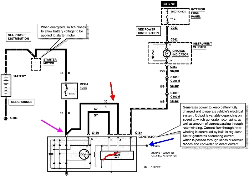
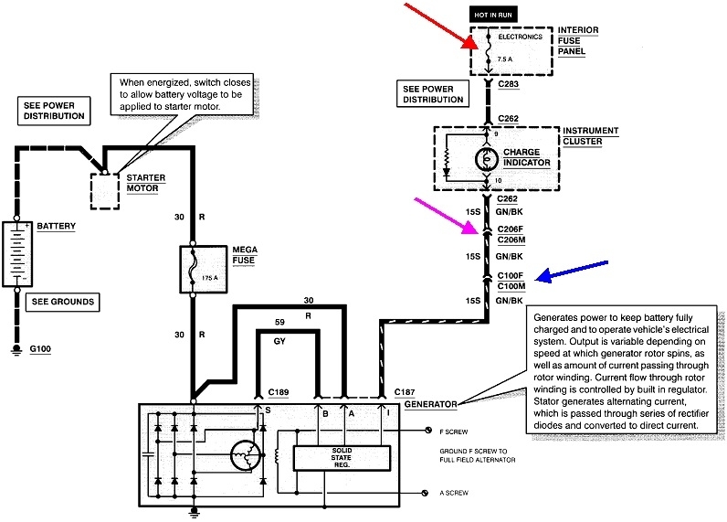
When it starts producing output, a sample of that is tapped off and appears on the white or white / black wire. (It's shown as gray on your diagram). That will be around 6 - 7 volts. That wire goes right into the voltage regulator and it's that voltage that tells the regulator the generator is working. In response, the regulator puts full battery voltage back out on the green / black wire. With full voltage there, and full voltage on the other side of the dash light, the difference is 0 volts, so the warning light turns off.

The interesting thing is all "AC generators", (aka "alternator), put out three phase output which is very smooth compared to rectified 60 cycle single-phase house current. That gray wire taps off just one of those three phases, so only that one phase has to be working to turn the warning light off.

When one of the six main diodes fails, you lose one phase of output. Because of the interaction between the phases, each diode is used in multiple phases, but at different times. As a result, when one of the three phases is lost, you will lose exactly two-thirds of the generator's output capacity. A common 90-amp generator will only develop a maximum of around 28 - 32 amps under a full-load test. That's enough to keep an older vehicle going, but with all the electronics on newer models, the battery will have to make up the difference as it slowly runs down over days or weeks.

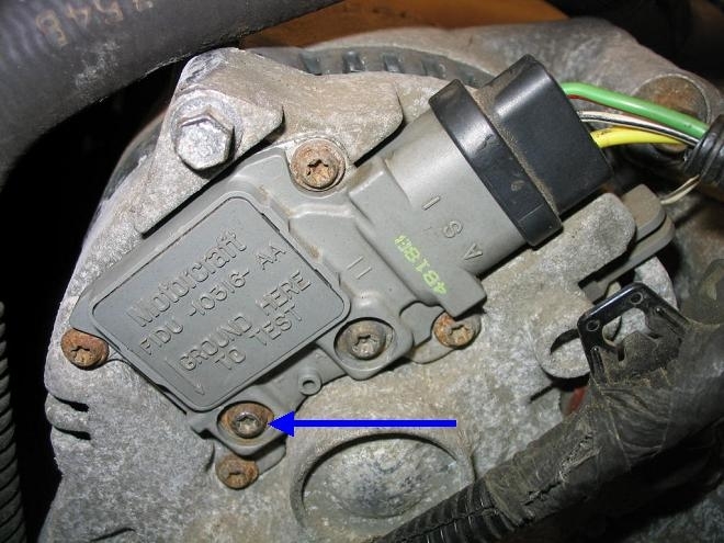
If a second diode fails, you could lose even more output capacity, as long as it's the right second diode. They call them the three "negative" diodes and the three "positive" diodes. Both are exactly the same electrically. The polarity designation actually refers to how they're placed in the circuit. If one positive diode, for example, were to short, you'd lose that one phase of output, but if any one of the negative diodes also shorts later, that would create a dead short to ground and the 175-amp maxi-fuse would blow. We know that's not the case here because you found battery voltage on the output stud. That had to come through the maxi-fuse.

All three positive diodes or all three negative diodes could short, (extremely unlikely), and you'd have no output at all, but in either case, it's the good diodes that would still stand in the way of causing a dead short to ground.

The point is, you can have two failed negative diodes or two failed positive diodes, resulting in very low output capacity, but if the phase that the gray wire is tapped off is the one that's still working, the voltage regulator will see that as a working generator and it will turn off the warning light. I've run into a number of generators with a failed diode, but never with two, so I don't know what kind of output you'd be able to get.

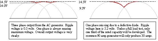
Here's a drawing I put together to show another dimension to this story. The left chart shows the overlapping output from three properly-working phases. The red line shows the output voltage that would be seen at the generator's output stud. That's called the "ripple" voltage and gets measured by most charging system testers other than the less-complicated hand-held type. That's the same voltage that goes right back through the regulator on the smaller red wire, and is what provides the current to run the field winding which creates the rotating magnetic field.

The second chart shows that ripple voltage goes way up when one phase is missing due to a failed diode. Two things are different than in the past with this regulator. First, older voltage regulators turned the warning light on if generator output went to "0". This regulator can also turn the light on if output voltage goes low or too high. Second, this type of regulator circuit can respond in one of two ways when ripple voltage is high due to the failed diode. Some will see the 9.3 volts I used in the chart and respond by trying to get charging voltage back up. Output voltage could reach 16 volts or more, but the regulator is still seeing 9.3 volts. Testing this system would show output voltage is too high while full-load output current is one-third of what it should be. Conclusion would be a failed diode / replace the generator.

Some voltage regulator designs respond to the high point of the ripple voltage, in this case a perfect 14.5 volts. In response they wouldn't try to change anything, but since it's the same ripple voltage that feeds the field winding, during the times the ripple voltage drops to 9.3 volts, it's that lower voltage that would create a much weaker electromagnetic field, and therefore much lower output current. Lower output current is the result of lower output voltage, and that turns right around and creates a lower magnetic field. It's a vicious circle that makes output voltage drop a lot during that missing phase, but the regulator still sees the 14.5 volts and thinks everything is normal. With this regulator design, under the full-load test, you'd again find output current to be one-third of the generator's maximum rating, but output voltage would look okay.

All of these test results can be aggravated by digital voltmeters. They take a reading, analyze it, then display the results while it takes the next reading. Some of the fastest meters might take two or three readings per second, and one of those could be right in the middle of the missing phase, and the next one could be when a different phase is producing its highest voltage. The meter's display would be bouncing around and would likely be hard to read. The battery will smooth those voltage fluctuations out a lot, so you may get a usable reading right across the battery terminals, but the reading at the other end of that fat wire at the generator's output stud is bouncing around. Even though that's just a big wire with very little resistance in it, it only takes a tiny amount of resistance to make the readings different at each end. Partly for convenience, but also partly because of this smoother meter readings at the battery is why professional charging system testers have us connect the voltmeter leads at the battery and not at the generator.

To answer your original question, see what you have for voltage on the generator's output stud with the engine running. It needs to be between 13.75 and 14.75 volts. All generators are inefficient at low speeds, so testing is normally specified with engine speed at 2,000 rpm. For the testing you're doing, it is sufficient to simply raise engine speed a little. Let me know what you find there.

If the voltage stays at battery voltage of 12.6 volts or less, there could be some other defect inside the generator, but also check for a loose belt. Yours uses a bolted-on pulley. I suppose that nut could work loose, but I suspect things would have gotten worse real quickly, as in the pulley and belt fell off. A lot of newer models are using a clutch-type pulley that is supposed to reduce vibration. A friend gave me one that he replaced after it seized, but I can't remember the symptoms he ran into. I could see how they could get weak and slip too. Belt slippage with a serpentine belt is pretty uncommon unless the spring-loaded tensioner pulley is weak, but then you'd hear the belt squeal. On older GM and Ford generators that had the fan outside right behind the pulley, push on a blade of that fan with your thumb. (For others researching this topic, .. Do that with the engine not running!). Those mostly go back to the days of V-belts. If the pulley can be spun and it slips under the belt, that belt is too loose or it has worn on the sides until it is running on the bottom of the pulley instead of being gripped on the two sides. When the belt is tight enough, it's pretty common to be able to turn the crankshaft just by pushing on the generator's fan blade. In this case of "tight is good", tighter is not better. Over-tightening the belt puts too much stress on bearings. That can lead to early failure of the water pump, power steering pump, or generator bearings.
Was this
answer
helpful?
Yes
No
+1
Monday, December 28th, 2020 AT 2:24 PM
Tiny
QFONG
  • MEMBER
  • 92 POSTS
Engine speed was at 1,200 RPM's and voltage at gen was 11.8 and falling.
Was this
answer
helpful?
Yes
No
Tuesday, December 29th, 2020 AT 9:47 AM

Please login or register to post a reply.

Sponsored links