Alternator and charge light both not working

Tiny
CARADIODOC
  • MECHANIC
  • 33,741 POSTS
That verifies for a second time the maxi-fuse is okay and 12 volts should be getting to the regulator on the smaller red wire. The last thing to try is to ground the "F" test terminal on the back of the generator. That will bypass the voltage regulator, so if it is defective, the generator will start charging wide-open. I think this is not going to work because the regulator already thinks the system is working as it has turned off the warning light, but lets try it anyway.

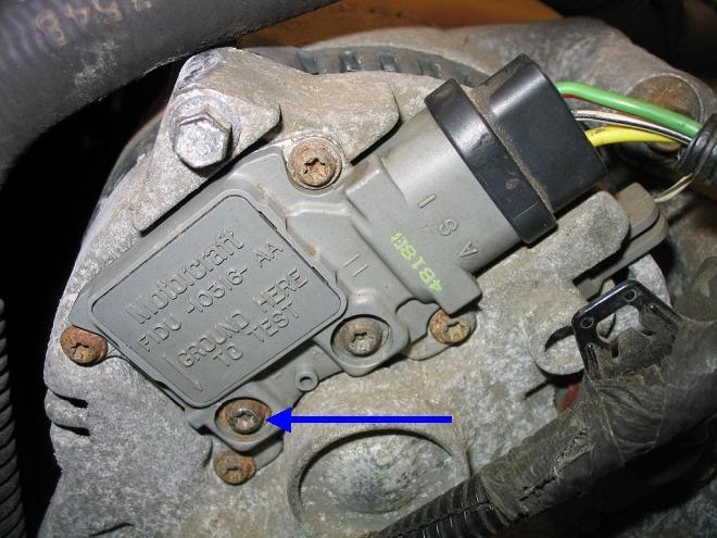
This photo is from a Tempo, but your regulator should look the same. The blue arrow is pointing to the screw head that needs to be grounded with a clip lead or any piece of wire. You'll note that this one is rather rusty, so it would be necessary to scratch at it a little to make a good momentary connection. Same with the surface corrosion on the generator's housing.

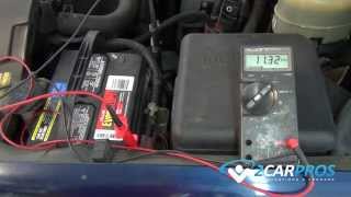
If this works, you'll suddenly hear the generator whine a little, and load the engine down as it starts charging. If you have the head lights on or you have a helper watching the voltmeter at the battery, you'll see system voltage start to rise. If this test indicates the regulator is defective, it can often be replaced without removing the generator from the engine, as is the case here with the Tempo. Remove the four screw in the four corners, not the one with the blue arrow or the other one across from it. These should be T15 or T20 Torx heads.

If you remove the "A" screw and the "F" screw, (blue arrow), the brush assembly will detach from the regulator. Doesn't matter as a new regulator comes with a new set of brushes already bolted on and ready to install. Notice too the small hole between the "A" and "F" screws. There will be a small wooden stick, like a toothpick, in there. That's to hold the brushes retracted so they'll slip over the slip rings without being cracked or damaged. Once the regulator is bolted on, slide that stick out and you'll hear the spring-loaded brushes snap into place.

I'm betting there will be no change when you ground the "F" terminal. That would point to some defect within the generator. The best suspect I can think of is the output stud's connection has burned off just inside the housing. That would leave the circuit intact that is monitored by the regulator to know when the system is working, and 12 volts would still show up on the smaller red wire from the battery to keep the regulator working. The only other defect I can think of would be multiple failed diodes. With some physical designs, especially on older Chrysler products, a shorted diode would overheat, then burn off one of its connections, so it would no longer pose a potential dead short if a second diode were to short. In that way, there could be as many as three or four defective diodes that would cause no or low charge, but no blown fuses.

There's one more thing to peek at. Your generator should be bolted solidly to the metal mounting bracket. If it is, this doesn't apply. On a few models, generators are mounted on rubber bushings to isolate them from engine vibration. As such, they have to use a separate bolted-on ground cable between the generator's housing and any point on the engine. That cable or braided strap can corrode off resulting in a no-charge condition. The often-overlooked clue is if you measure voltage with the meter's ground probe on the engine block, you'll find 12 volts on the generator's housing.
Was this
answer
helpful?
Yes
No
+1
Tuesday, December 29th, 2020 AT 12:16 PM
Tiny
QFONG
  • MEMBER
  • 92 POSTS
Good info. It's going to take me 2 or 3 days to do these tests as the v6 gen is mounted in a very difficult spot. For instance I have to remove the exhaust crossover to get to any part of the gen except the battery terminal.
Was this
answer
helpful?
Yes
No
Tuesday, December 29th, 2020 AT 12:42 PM
Tiny
CARADIODOC
  • MECHANIC
  • 33,741 POSTS
I'll be here.
Was this
answer
helpful?
Yes
No
+1
Tuesday, December 29th, 2020 AT 2:08 PM
Tiny
QFONG
  • MEMBER
  • 92 POSTS
How do you get at the top bolt on the generator? I can't even see it.
Was this
answer
helpful?
Yes
No
Sunday, January 3rd, 2021 AT 3:36 PM
Tiny
CARADIODOC
  • MECHANIC
  • 33,741 POSTS
I'd be embarrassed to be the engineer who came up with this design. It sounds worse than removing the radiator on an Aerostar to replace the generator. Before you go through all of this, were you able to do the full-field test by grounding the "F" screw? If that produced output, you can get away with just replacing the voltage regulator if that will be easier. You might also perform a continuity test between the "A" and "F" screws. You should find close to 4 ohms, but it's common and normal to need to irritate the belt and pulley a little to get a good reading. If you still come up with an open circuit, the brushes are worn. They come as part of the voltage regulator, so again, that might be an easier repair. Consider looking at any Ford generator from the mid '90s at a salvage yard if that will help to know what you're looking at. Starting around 1999 to the early 2000s, the engineers figured out they made them much too easy to diagnose and to repair, so they added a cover to the rear so you couldn't do that any more.

Here's what I found for your car:

1. Disconnect the battery ground cable, then disengage the alternator drive belt from the alternator pulley.
2. Raise and support the vehicle, then remove the righthand wheel and tire.
3. Remove the righthand outer tie rod end from righthand spindle.
4. Remove exhaust system Y pipe as follows:
a. Remove the front and rear Y pipe flange fasteners from the exhaust manifolds.
B. Remove the stud bolt and nut retainer from the oil pan, then remove the two remaining nuts and bolts from U pipe outlet connection.
C. Discard the exhaust converter inlet gasket, then remove the Y pipe.
5. Disconnect wire harness attachments to integral alternator/voltage regulator, then remove the alternator brace bolts from the alternator.
6. Remove the righthand halfshaft.
7. Remove the alternator bolts from bracket, then rotate the alternator and remove it through the righthand side of the vehicle.
8. Remove the bracket bolts and bracket from the cylinder block.
9. Reverse the procedure to install, noting the following:
a. Torque the alternator bracket bolts to 15-22 ft lb.
B. Torque the alternator bolts to 29-40 ft lb.
C. Torque the alternator brace bolts to 15-22 ft lb.
D. Torque the output terminal nut to 6.7-8.1 ft lb.
Was this
answer
helpful?
Yes
No
+1
Sunday, January 3rd, 2021 AT 5:28 PM
Tiny
QFONG
  • MEMBER
  • 92 POSTS
The only problem is that I can't get to the terminals. The generator is in such a position that I can only get to the battery terminal on the gen. The voltage regulator is up toward the top, back of the gen and close to the block so I can't possibly get to the A and F terminals. I have no recourse but to remove the gen.
Was this
answer
helpful?
Yes
No
Sunday, January 3rd, 2021 AT 5:44 PM
Tiny
CARADIODOC
  • MECHANIC
  • 33,741 POSTS
Rats. Perhaps talk with a mechanic at a Ford dealership first. I had what I thought was a tough one on a Dodge Dynasty many years ago. Turns out the job was real easy if the car was up on a hoist. The exhaust pipe had to be dropped on the earlier model years, because they used a physically larger alternator, but by '92 and '93, they were using a much smaller unit, but they never rewrote the removal instructions. Those two exhaust bolts were easy to remove as long as you could stand up under the car. The Ford mechanics may haver some similar tips to make your job easier.
Was this
answer
helpful?
Yes
No
+1
Sunday, January 3rd, 2021 AT 5:59 PM
Tiny
QFONG
  • MEMBER
  • 92 POSTS
Okay, thanks.
Was this
answer
helpful?
Yes
No
Sunday, January 3rd, 2021 AT 7:35 PM
Tiny
QFONG
  • MEMBER
  • 92 POSTS
I found a video on YouTube that shows a guy removing the gen from under the car using an 18" extension, a u-joint and 13 mm short socket. Then the bolt will drop out. Getting it back in might be a big problem. I'm thinking of re-engineering the gen mounting so that the bolts go in from the wheel well side.
Was this
answer
helpful?
Yes
No
Monday, January 4th, 2021 AT 5:30 PM
Tiny
QFONG
  • MEMBER
  • 92 POSTS
I got the gen out of the car and found one of the problems. The wires coming out of the 3 circuit connector and the single circuit connector all have lost most of their insulation. So I am going to have to run new wires. The confusing part is that the small red wire goes into the loom with the green/blk wire so I assume it joins a hot wire with a fuse somewhere. I don't see this on a schematic so hopefully you can verify this for me.
Was this
answer
helpful?
Yes
No
Wednesday, January 6th, 2021 AT 3:31 PM
Tiny
CARADIODOC
  • MECHANIC
  • 33,741 POSTS
I do remember that red wire going into the harness. On most models that's a yellow wire and is fed from its own dedicated 10 or 15-amp fuse. (We had a few Ford models donated to my community college. I built in a number of "bugs" for my students to diagnose, and a lot of them were in this charging circuit).

I can't remember where the other end of your red wire is. It seems to me it would take more labor, and be less-reliable, to splice it to the battery wire inside the harness. It would make more sense to crimp it to the large terminal alongside the battery wire.
Was this
answer
helpful?
Yes
No
+1
Wednesday, January 6th, 2021 AT 5:01 PM
Tiny
QFONG
  • MEMBER
  • 92 POSTS
I'll do that, meanwhile since the alternator is out of the car and is so difficult to access, I'm going to replace the regulator and test or/and replace the diodes.
I found that removing the upper bolt was`difficult but not as bad as it looked so I'll leave the mounting as it is.
Was this
answer
helpful?
Yes
No
+1
Wednesday, January 6th, 2021 AT 6:30 PM
Tiny
CARADIODOC
  • MECHANIC
  • 33,741 POSTS
You have to do a lot of disassembly to check the diodes. It isn't practical to replace them on most designs.

While not in operation, the wires of the stator windings are right across the diodes, and are in fact, a dead short. That means with the diode test that's on most digital meters will read them as shorted. On older GM and Chrysler generators, the stator windings could be unbolted from the terminals of the diode blocks. That made testing them possible, and those blocks were easy to remove and replace. Today most stator windings are soldered to the diodes. GM's '87 and newer generators are especially difficult to disassemble without destroying parts. In particular, just to take the unit apart, you have to unsolder the diode block first, through the holes in the case, and by the time you get it apart, that diode block has been damaged beyond reuse.

To look at this from a different direction, diode failure on all except those newer GM generators is not real common. When one does short, the most output current you'll be able to get is exactly one-third of its maximum rated output. That's not enough to meet the demands of the entire electrical system under most conditions, so the battery will run down over days or weeks and have to be recharged with a portable charger. That failure is rare, but it's even less likely to be a second defect when you also run into a defective regulator or worn brushes. Based on that logic, I'd expect the system will work properly after repairing any wiring problems, and after replacing the regulator / brushes.

If you had a reason to suspect a diode failure, the best course of action is to replace the entire generator with a rebuilt one. If there was no problem before this failure-to-charge occurred, there isn't any benefit in trying to take it apart to test the diodes. Also, while I realize how miserable this job is and you don't want to do it again, most professional charging system testers will test for a defective diode. It shows up on most testers as "high", (bad), or "low", (normal) "ripple voltage". A few testers print out the actual ripple voltage value, but most just display it on a relative bar chart. Also, if the full-load output current test shows output current close to the 130 amps your generator is rated for, that would prove the diodes have to be okay.
Was this
answer
helpful?
Yes
No
+1
Wednesday, January 6th, 2021 AT 7:02 PM
Tiny
QFONG
  • MEMBER
  • 92 POSTS
Okay. Thanks for the advice. I'll replace only the regulator.
Was this
answer
helpful?
Yes
No
+1
Wednesday, January 6th, 2021 AT 8:19 PM
Tiny
QFONG
  • MEMBER
  • 92 POSTS
Wanted to let you know what's going on with my problem. I installed a new regulator on the gen and replaced the small wires that go to it. The slip rings of the rotor are worn so the gen will have to replaced soon. Now I am trying to install the gen on to the engine.
My work area is a carport but the last few days it's been too cold to go diving under the vehicle. I'll complete the work as soon as I can.
Was this
answer
helpful?
Yes
No
+1
Wednesday, January 13th, 2021 AT 11:15 AM
Tiny
CARADIODOC
  • MECHANIC
  • 33,741 POSTS
As long as it's out yet, do a quick continuity test between the "A" and "F" terminals. You should get close to 4.0 ohms plus a few in the meter's leads. If you get an open circuit, spin the pulley a little. I wouldn't be too worried about the slip rings. The new brushes will wear to match them. They only have to pass a maximum of three amps when the system is charging wide-open, which is almost never.

While this really can't happen with this design, check for continuity from each terminal, "A" and "F", to ground. Both must read open circuit. There have been some designs in the past where it was possible to overlook a brush's spring or wire making contact with the housing. Depending on which one that is, it will either cause a fuse or fuse link wire to blow, or it will cause the system to constantly charge wide-open. That will do a lot of damage if left that way. It's always good practice to do those quick checks, if for nothing more than peace-of-mind.
Was this
answer
helpful?
Yes
No
+1
Wednesday, January 13th, 2021 AT 5:38 PM
Tiny
QFONG
  • MEMBER
  • 92 POSTS
Okay, it checks out electrically. I got the gen partially installed back in the car and will probably be able to run the car tomorrow.
Was this
answer
helpful?
Yes
No
+1
Thursday, January 14th, 2021 AT 4:05 PM
Tiny
QFONG
  • MEMBER
  • 92 POSTS
14.5 volts at 1,500 RPMs, looks good to me. I didn't run it very long because the exhaust is open and the neighbors don't like loud noises. Tomorrow I should be able to put it all back together and drive it around a little.
Was this
answer
helpful?
Yes
No
+1
Friday, January 15th, 2021 AT 3:10 PM
Tiny
CARADIODOC
  • MECHANIC
  • 33,741 POSTS
Dandy. I'll be expecting another reply when it's back together.
Was this
answer
helpful?
Yes
No
+1
Friday, January 15th, 2021 AT 7:11 PM
Tiny
QFONG
  • MEMBER
  • 92 POSTS
Today I ran the car for an hour with the cooling fans and the high power running lights on. The gen put out 14.5 volts the whole time which brings up another question.
Last year when I rewired the PCM I had the unit sitting on the right side shock tower. The idle speed was about 750 RPMs. After I installed the PCM in it's mounting position the idle speed went up to 1,100 RPMs. I was wondering if I could have cut open a vacuum line. I know there is one down under all those wires. What do you think? I don't hear any hissing.
Was this
answer
helpful?
Yes
No
+1
Tuesday, January 19th, 2021 AT 3:11 PM

Please login or register to post a reply.

Sponsored links