Bench-testing generators is not the best way to diagnose this system. it's even less effective for starter motors. To add to the misery, you're describing an intermittent problem. Any testing has to be done while the problem is occurring. You don't know when that is during a bench test.
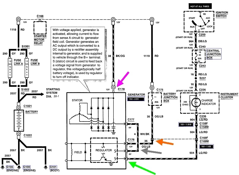
I have a suspicion there's worn brushes inside the generator, but to start the diagnosis, watch the red "Battery" warning light on the dash. That circuit provides the "wake-up", or "turn-on" signal to the voltage regulator. If that bulb lights up when you turn on the ignition switch, that circuit is okay. That ends in the light green / red wire in the three-wire plug at the side / back of the generator, (green arrow). Most of the 12 volts is used up across that bulb. What's left is the voltage you'll measure on that wire. If that's the wire you found 2.3 volts on, that's perfect. Once the engine is running and the charging system is working, the regulator will put full system voltage back out on that light green / red wire to turn the warning light off.
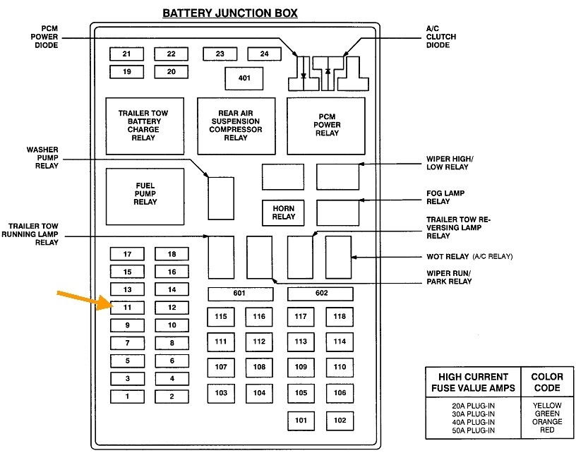
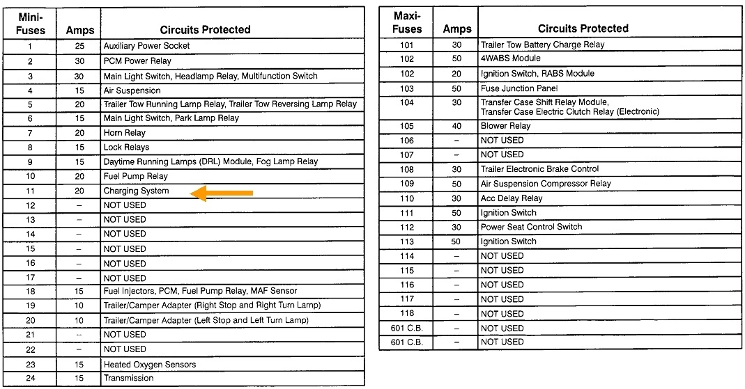
The orange / light blue wire, (orange arrow), provides the current to run the voltage regulator and the field current for the generator. You must find full battery voltage on that wire all the time. If it's missing, check the 20-amp fuse in the under-hood fuse box.
Also check for full battery voltage on the fat output wire bolted to the back of the generator. If that is missing, the fuse link wire is burned open. You'll have plenty of other symptoms besides a no-charge condition. That fuse wire burns open due to two or more shorted diodes in the old generator, or the output terminal was accidentally grounded when hit by a wrench when working in that area.
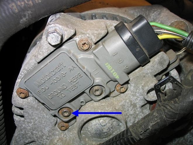
In addition to these tests, there's a test terminal on the back of the generator's housing, as shown in the second photo. By using a piece of wire to ground the screw the blue arrow is pointing to, that bypasses the voltage regulator. You can use a digital voltmeter across the battery terminals to watch what happens when you ground that screw, but it's just as easy to watch the brightness of the head lights or listen to the whine as the generator loads down the engine. I forgot to mention the engine must be running for this test. If system voltage goes up when the test screw is grounded, that proves the voltage regulator is defective. Those can be replaced separately by unbolting the screws in the four corners. New brushes come with the new regulator. You'll see the new brushes are held retracted with a tooth pick. That must be pulled out and discarded only after the regulator is bolted in place. You'll hear the two light clicks as the brushes pop into place as that tooth pick is removed.
If system voltage doesn't increase when the test terminal is grounded, it suggests the regulator is most likely okay and something else is causing the problem. The three previous voltage tests should identify that. To be valid, those voltage readings must be taken with the connector plugged in. Back-probe through the rubber seals alongside each wire to take those readings.
I haven't mentioned the white / black wire yet, (gray arrow). When the generator develops its proper output voltage of 13.75 to 14.75 volts, exactly half of that will appear on this white / black wire. It goes into the voltage regulator to tell it the system is working. That is what the regulator looks at to determine when to put system voltage back out on the light green / red wire to turn the warning light off. We typically don't bother to look at that white / black wire as part of any diagnosis.
Besides the no-charge condition, this voltage regulator is also capable of detecting an over-charge and an under-charge condition, and will turn on the warning light for those issues too.
There's one more defect to be aware of, but it is pretty much unheard of for it to be intermittent. That is one failed diode of the six. Your generator has two extra diodes to squeak out a little extra current capacity, but the story is the same. All AC generators, (aka "alternator"), develop three-phase output current which is much more stable and efficient than what comes out of a battery charger. One phase is lost when one diode fails, but that results in a loss of exactly two thirds of the generator's capacity to develop output current. The standard generator for your model is a 95-amp. With one failed diode, the most it will develop is around 30 amps. That's not enough to meet the demands of the entire electrical system, but more importantly, the voltage regulator will see the momentary drop in voltage on the white / black wire and will turn on the warning light in response. That momentary drop in voltage causes excessive "ripple voltage". Ripple voltage is measured automatically by most professional charging system testers and is used to identify the failed diode. Some testers that provide printouts may list ripple voltage as a voltage, but most of them just use flashing lights to indicate whether ripple voltage is high or low.
Ripple voltage may not be measured on all bench testers. Regardless, that isn't part of the diagnosis for a no-charge condition.
Let me know what you find up to this point. Remember, the plugs must remain connected, the testing must be done while the problem is occurring, and the engine must be running to spin the generator's pulley. You can perform the various tests while the system is working if you'd like to see what "normal" is, but we need to see those readings when the system isn't charging.
Images (Click to enlarge)
May 9, 2022 at 9:31 AM