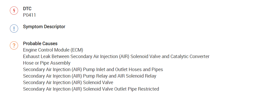
Okay, I attached the description and the possibilities below for you to view.
Can you hear the pump turn on when you start it first thing in the morning? The pump is the most common failure for this code.
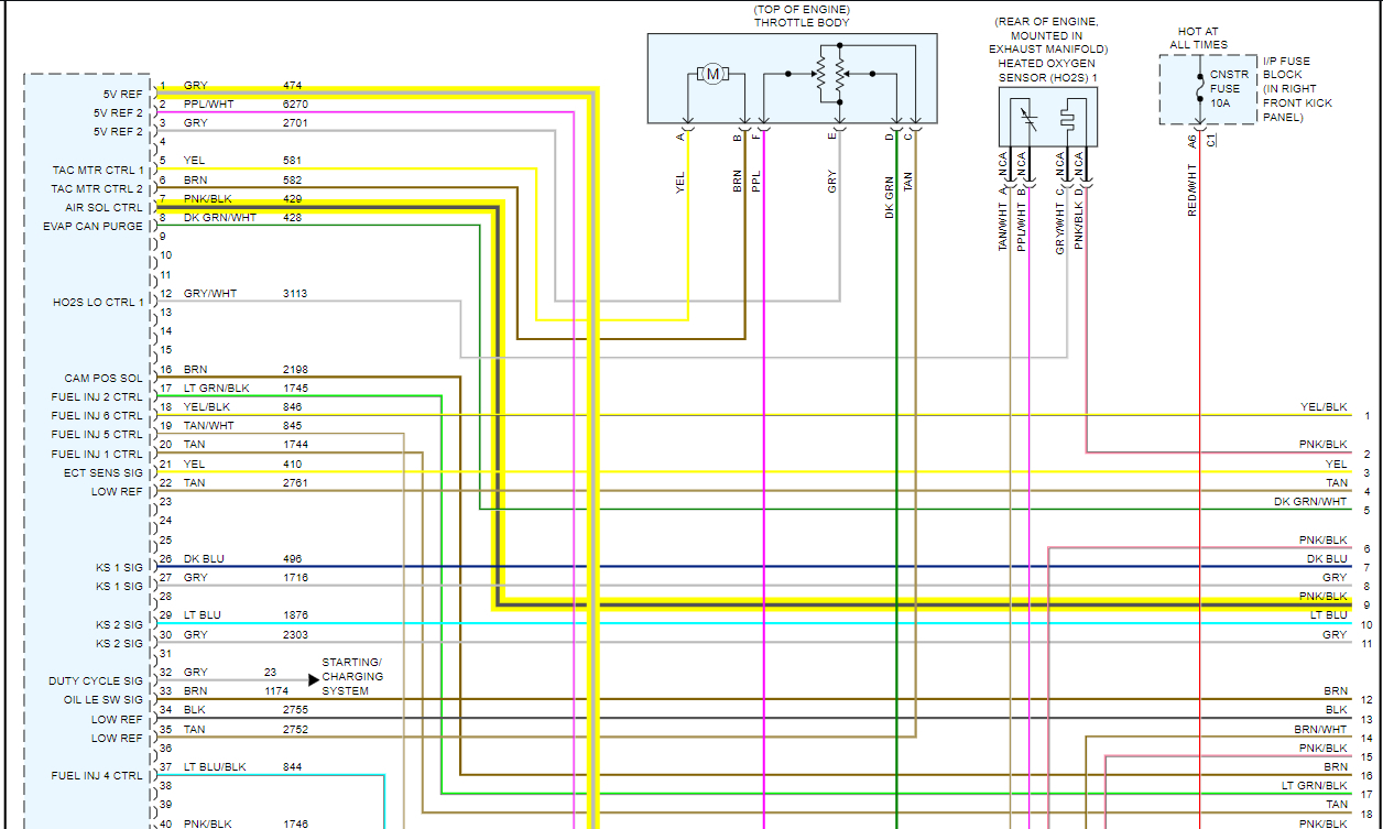
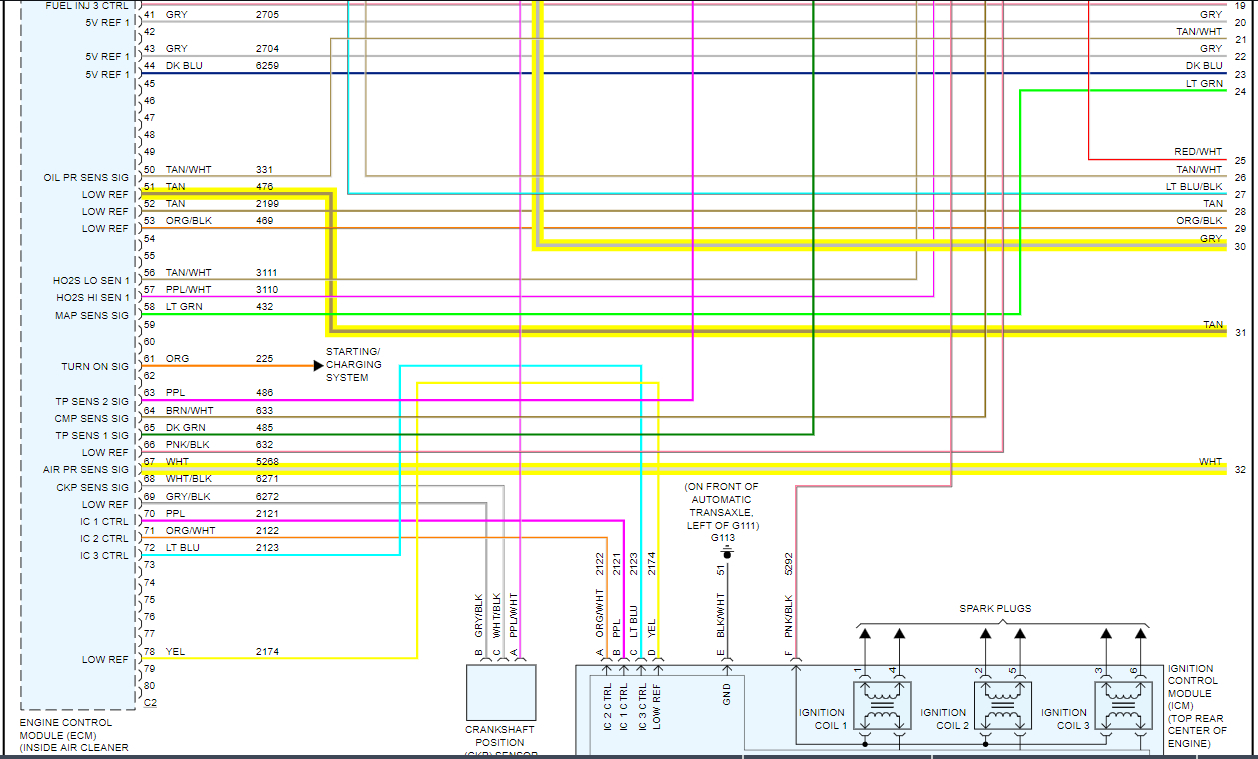
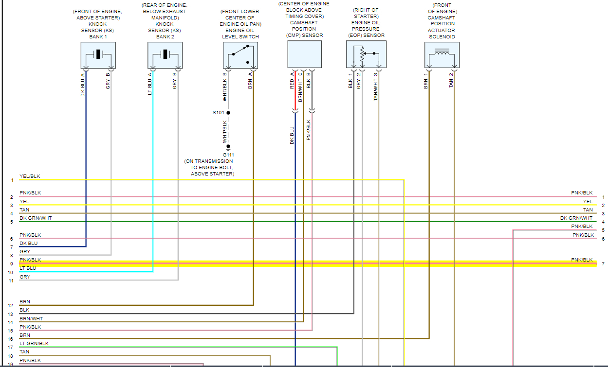
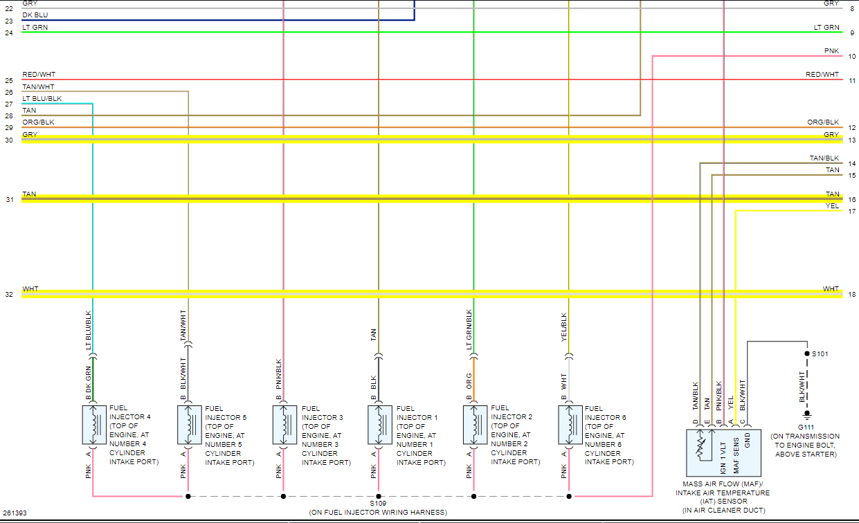
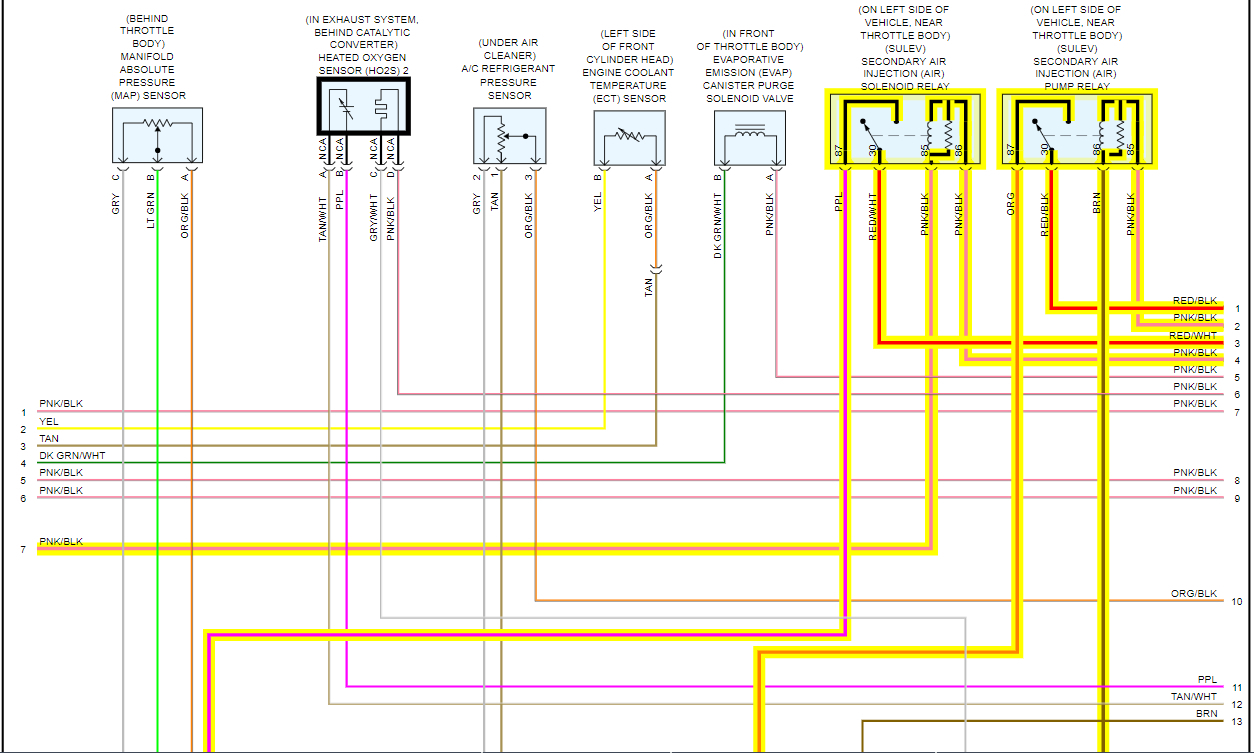
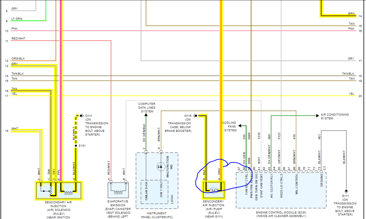
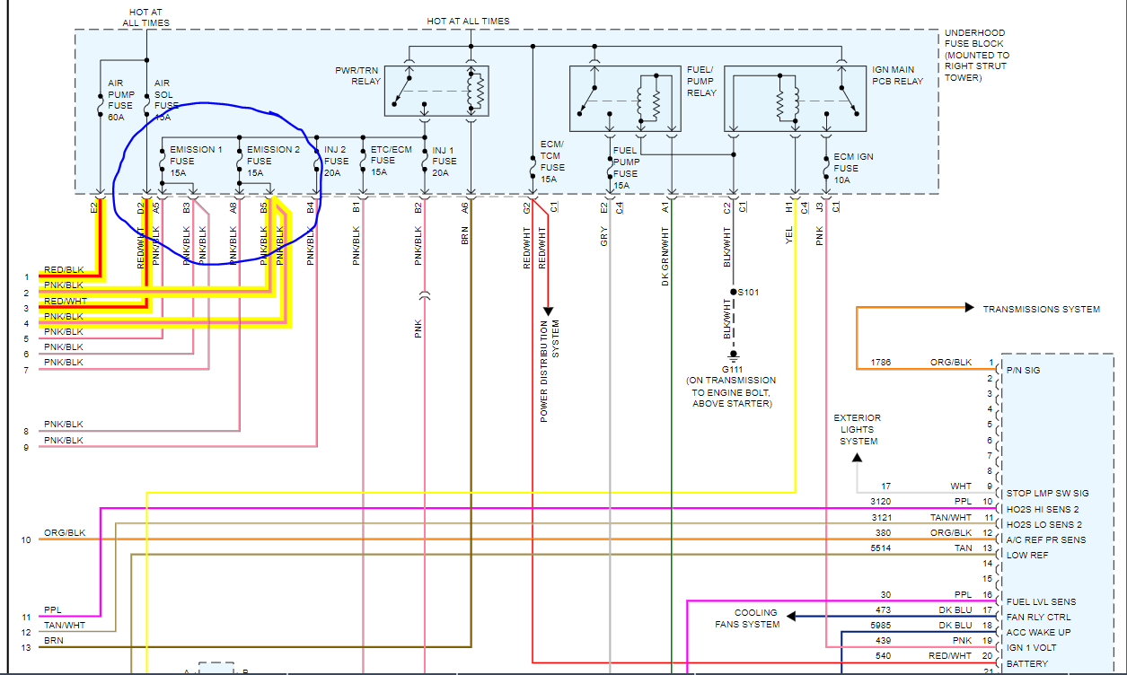
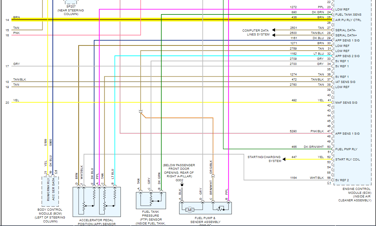
I attached the wiring diagram as well. You need to test the orange wire at the pump for power within the first 3 minutes of when the car starts from an overnight sit.
https://www.2carpros.com/articles/how-to-check-wiring
Roy
Circuit/System Description
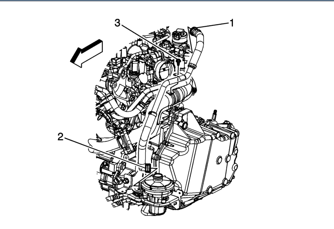
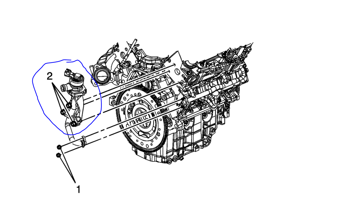
The secondary air injection (AIR) system aids in the reduction of hydrocarbon emissions during a cold start. The system forces fresh filtered air into the exhaust stream in order to accelerate the catalyst operation. An electric air pump, the secondary AIR injection pump, provides filtered air on demand to the AIR control solenoid valve/pressure sensor assembly. The AIR control solenoid valve/pressure sensor assembly controls the flow of air from the AIR pump to the exhaust manifold. The AIR valve relay supplies the current needed to operate the AIR control solenoid valve/pressure sensor assembly. A pressure sensor is used to monitor the air flow from the AIR pump. The engine control module (ECM) supplies the internal pressure sensor with a 5-volt reference, an electrical ground, and a signal circuit.
The AIR diagnostic uses 3 phases to test the AIR system:
1. DTCs P0411 and P2430 run during Phase 1
2. DTCs P2430 and P2440 run during Phase 2
3. DTC P2444 runs during Phase 3
During phase 1, both the AIR pump and the solenoid valve are activated. Normal secondary air function occurs. Expected system pressure is 8-10 kPa above BARO.
During phase 2, only the AIR pump is activated. The solenoid valve is closed. Pressure sensor performance and solenoid valve deactivation are tested. Expected system pressure is approximately 15-22 kPa above BARO.
During phase 3, neither the AIR pump nor the solenoid valve is activated. AIR pump deactivation is tested. Expected system pressure equals BARO.
In all 3 phases, testing is accomplished by comparing the measured pressure against the expected pressure. The ECM can detect faults in the AIR pump, AIR control solenoid valve/pressure sensor assembly, and the exhaust check valve. The pressure sensor can also detect leaks and restrictions in the secondary AIR system plumbing.
Conditions for Running the DTC
DTC P0101, P0102, P0103, P0107, P0108, P0112, P0113, P0116, P0117, P0118, P0201-P0206, P0300, P0412, P0418, P0420, P0606, P2430, P2431, P2432, P2433
The system voltage is 9-18 volts.
The start-up engine coolant temperature (ECT) is between 5-50°C (41-122°F).
The start-up intake air temperature (IAT) is between 5-60°C (41-140°F).
The BARO parameter is more than 60 kPa.
The MAF sensor parameter is between 3-24 g/s.
The AIR system is commanded ON.
The conditions are stable for more than 5 seconds.
DTC P0411 runs once per trip start up when the above conditions are met and AIR pump operation is requested.
Conditions for Setting the DTC
The difference between the predicted system pressure and the actual system pressure is more than 4 kPa.
DTC P0411 sets within 22 seconds when the above condition is met.
Action Taken When the DTC Sets
DTC P0411 is a Type B DTC.
Conditions for Clearing the MIL/DTC
DTC P0411 is a Type B DTC.
Circuit/System Verification
1. If any other AIR DTCs are set, perform those diagnostics first.
2. Engine running, observe that the AIR Pressure Sensor parameter approximately equals barometric pressure (BARO).
3. Engine running, enable the AIR pump with a scan tool and observe that the AIR Pressure Sensor parameter equals approximately 15-20 kPa above BARO.
4. Engine running, enable the AIR solenoid with a scan tool and observe that the AIR Pressure Sensor parameter equals approximately 8-10 kPa above BARO.
Circuit/System Testing
Important: Circuit/System Verification MUST be performed first or misdiagnosis may result.
1. Ignition ON, observe that the AIR pump is not activated.
If the AIR pump is activated, test the AIR pump voltage supply circuit for a short to voltage. If the circuit tests normal, test the AIR pump relay control circuit for a short to ground. If the circuits test normal, test the AIR pump relay. If the relay and circuits test normal, replace the ECM.
2. Ignition ON, enable the AIR pump with a scan tool and observe that the AIR pump is activated.
If the AIR pump is not activated, test the AIR pump voltage supply and ground circuits for more than 2 ohms of resistance. If the circuits test normal, test both AIR pump relay voltage supply circuits for an open/high resistance or a short to ground. If the circuits test normal, test the AIR pump relay control circuit for an open/high resistance or a short to voltage. If the circuits test normal, test the AIR pump relay. If the relay and circuits test normal, test the AIR pump. If the relay, pump, and circuits test normal, replace the ECM.
3. Ignition OFF, disconnect the harness connector at the AIR solenoid.
4. Connect a test lamp between the AIR solenoid voltage supply and ground circuit terminals.
5. Ignition ON, observe that the test lamp is not illuminated.
If the test lamp is illuminated, test the AIR solenoid valve voltage supply circuit for a short to voltage. If the circuit tests normal, test the AIR solenoid valve relay control circuit for a short to ground. If the circuits test normal, test the AIR solenoid valve relay. If the relay and circuits test normal, replace the ECM.
6. Enable the AIR solenoid with a scan tool and observe that the test lamp is illuminated.
If the test lamp is not illuminated, test the AIR solenoid voltage supply circuit and both AIR solenoid relay voltage supply circuits for an open/high resistance or a short to ground. If the circuits test normal, test the AIR solenoid ground circuit for an open/high resistance. If the circuits test normal, test both AIR solenoid relay control circuits for and open/high resistance or a short to voltage. If the circuits test normal, test the AIR solenoid relay. If the relay and circuits test normal, replace the ECM.
7. Ignition OFF, connect all wiring harness connectors.
8. Engine RUNNING, enable the AIR solenoid valve with a scan tool and observe that the AIR Pressure Sensor parameter equals approximately 8-10 kPa above BARO.
If not within the specified range, continue with this procedure.
9. Remove the AIR inlet hose from the AIR pump.
10. Engine RUNNING, enable the AIR solenoid valve with a scan tool and observe that the AIR Pressure Sensor Parameter increases to 8-10 kPa above BARO.
If within the specified range, the AIR pump inlet hoses/pipes are restricted. Remove the restriction or replace the hose/pipe.
If not within the specified range, continue with this procedure.
11. Disconnect the hose from the AIR pump outlet.
12. Disconnect the hose from the AIR solenoid valve inlet.
13. Install a length of standard 1 inch I.D. (25.4mm) hose from the AIR pump outlet to the AIR solenoid valve inlet.
14. Engine RUNNING, enable the AIR solenoid valve with a scan tool and observe that the AIR Pressure Sensor Parameter increases to 8-10 kPa above BARO.
If within the specified range, the AIR pump outlet hoses/pipes are restricted or leaking. Remove the restriction or replace the hose/pipe.
If less than the specified range, replace the AIR pump.
If more than the specified range, continue with this procedure.
15. Remove the AIR solenoid valve.
16. Leave the standard hose and harness connector connected.
17. Engine RUNNING, enable the AIR solenoid valve with a scan tool and observe that the AIR Pressure Sensor Parameter increases to approximately 7 kPa above BARO.
If more than the specified range, replace the AIR solenoid valve.
If within the specified range, the exhaust system is restricted. Remove the restriction or replace the appropriate component.
Component Testing
Relay Test
1. Test between the normally-closed switch terminals, if any, for 0 ohms.
2. Test between the normally-open switch terminals for infinite ohms.
3. Test between each switch terminal and either coil terminal for infinite ohms.
4. Connect the relay coil terminals to ground and fused power to energize the relay.
5. Test between each switch terminal and each coil terminal for 0 volts.
6. Test between the normally-closed switch terminals, if any, for infinite ohms.
7. Test between the normally-open switch terminals for 0 ohms.
Pump
1. Connect the AIR pump to fused battery voltage and ground and observe pressurized airflow at the pump outlet.
If pressurized airflow is not observed, replace the pump.
Solenoid Valve
1. Apply fused battery voltage and ground to the solenoid and verify that the valve opens and closes completely as voltage is applied to and removed from the solenoid. Observe that the valve is not obstructed or leaking.
If the valve operates incorrectly, leaks, or is obstructed, remove the obstruction or replace the valve.
Repair Instructions
Secondary Air Injection Pump Replacement
Engine Control Module Replacement for control module replacement and programming
Repair Verification
1. With the ignition ON and the engine OFF, observe that the AIR pump is not operating.
2. With the engine running, enable the AIR solenoid with a scan tool and observe that the AIR Pressure Sensor parameter equals approximately 8-10 kPa above BARO.
3. With the engine running, enable the AIR pump with a scan tool and observe that the AIR Pressure Sensor parameter equals approximately 15-20 kPa above BARO.
Images (Click to enlarge)
Nov 2, 2020 at 12:25 PM