Good morning.
There is a blend door actuator that controls heat and cold commands from the control head. It is a very common failure for this issue.
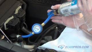
Before assuming this, the AC system needs to be checked for proper pressure. You need a set of gauges to confirm. You can rent them at a parts store.
The tough part is that the dash has to be removed in order to access the blend door as it is located on top of the heater case.
Roy
https://www.2carpros.com/articles/replace-blend-door-motor
https://www.2carpros.com/articles/car-air-conditioner-not-working-or-is-weak
Warning: On vehicles equipped with airbags, disable the airbag system before attempting any steering wheel, steering column, or instrument panel component diagnosis or service. Disconnect and isolate the battery negative (ground) cable, then wait two minutes for the airbag system capacitor to discharge before performing further diagnosis or service. This is the only sure way to disable the airbag system. Failure to take the proper precautions could result in an accidental airbag deployment and possible personal injury.
1. Disconnect and isolate the battery negative cable.
2. Remove A/C housing from vehicle.
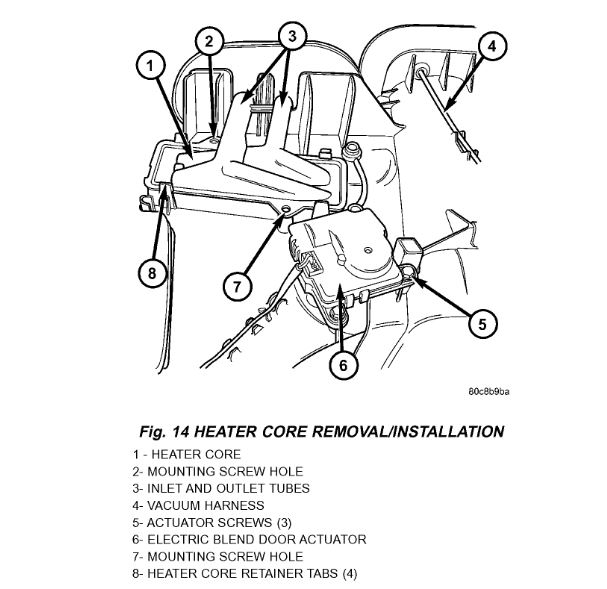
Fig.14 Heater Core Removal/Installation
imageZoom/Print
3. Remove the screws that secure the blend door actuator to the top of the HVAC housing..
4. Remove the blend door actuator.
INSTALLATION
1. Install the blend door actuator in place.
2. Install and tighten the screws that secure the blend door actuator to the housing. Tighten the mounting screws to 2.4 (± 0.34) Nm (21 (± 3) in. lbs.).
3. Install the HVAC housing into the vehicle.
4. Install the blend door actuator electrical connector from the wiring harness through the glove box.
5. Connect the battery negative cable.
panel removal
REMOVAL
Warning: on vehicles equipped with air-bags, disable the airbag system before attempting any steering wheel, steering column, seat belt tension-er, or instrument panel component diagnosis or service. Disconnect and isolate the battery negative (ground) cable, then wait two minutes for the airbag system capacitor to discharge before performing further diagnosis or service. This is the only sure way to disable the airbag system. Failure to take the proper precautions could result in accidental airbag deployment and possible personal injury.
Note: Before starting this procedure, be certain to turn the steering wheel until the front wheels are in the straight-ahead position.
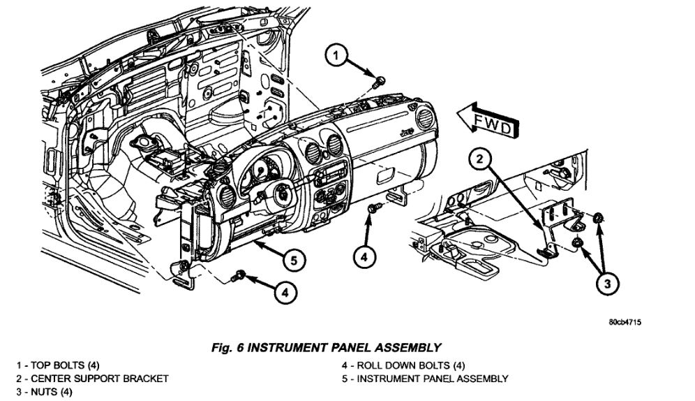
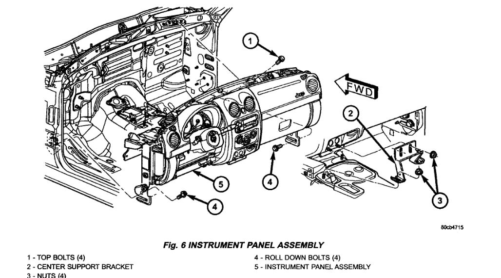
Fig. 6
imageZoom/Print
(1)Disconnect and isolate the battery negative cable.
(2)Remove the instrument panel top cover. See: Dashboard / Instrument Panel > Removal and Replacement > Instrument Panel Top Cover
(3)Remove the speakers.
(4)Remove the floor console. Refer to Body and Frame/Interior Trim/Console. See: Console > Service and Repair
(5)Remove the radio.
(6)Remove the four nuts and remove the center support bracket.
(7)Remove the steering column.
(8)Remove the drivers side cowl trim cover. Refer to Body and Frame/Interior Trim/Console/Service and Repair/Procedures. See: Console > Procedures > Cowl Trim Cover
(9)Disconnect the wire harness connector behind the drivers side cowl trim cover.
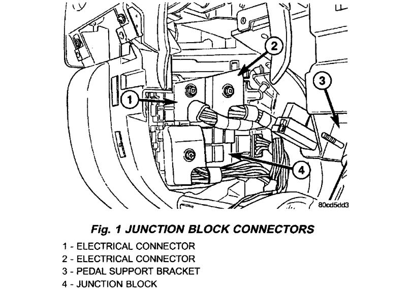
Fig. 1
imageZoom/Print
(10)Disconnect the green and light blue wire harness bulk connectors at the junction block.
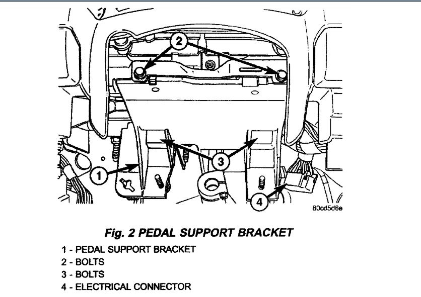
Fig. 2
imageZoom/Print
(11)Disconnect the electrical connector at the inner side of the pedal support bracket. (Fig. 2)
(12)Remove the two bolts at the front of the pedal support bracket. (fig. 2)
(13)Remove the two bolts from the bottom side of the pedal support bracket. (Fig. 2)
Fig. 6
imageZoom/Print
(14)Remove the two roll down bracket bolts at the left cowl side panel. (fig. 6)
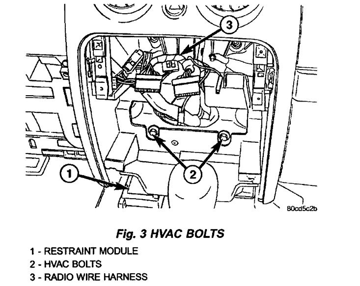
Fig. 3
imageZoom/Print
(15)Remove the ground strap bolt and disconnect the restraint module electrical connector. (Fig. 3)
(16)Remove the glove box. See: Glove Compartment > Removal and Replacement > Glove Box
(17)Remove the two HVAC mounting bolts behind the center trim. (Fig. 3)
(18)Remove the passenger side trim bezel. See: Dashboard / Instrument Panel > Removal and Replacement > Instrument Panel Trim Bezel - Passenger
Fig. 4
imageZoom/Print
(19)Remove the HVAC mounting bolt above the glove box striker. (Fig. 4)
Fig. 5
imageZoom/Print
(20) Remove the HVAC bolt at the lower outside corner of the glove box opening. (Fig. 5)
(21)Remove the passenger side cowl trim cover. Refer to Body and Frame/Interior Trim/Console/Service and Repair/Procedures. See: Console > Procedures > Cowl Trim Cover
Fig. 5
imageZoom/Print
(22)Disconnect the blower resistor electrical connector. (Fig. 5)
(23)Remove the two roll down bracket bolts at the right cowl side panel.
(24)Disconnect the vacuum check valve and the vacuum reservoir. (Fig. 5)
(25)Disconnect the blower motor electrical connector.
(26)Remove the four bolts at the top of the instrument panel connecting to the cowl front panel.
(27)Roll the instrument panel rearward and remove the wire harness from routing channel in the rear.
(28)Disconnect the push pin fastener and position aside the radio wire harness. Note the location of the harness for installation.
(29)Remove the instrument panel.
INSTALLATION
Warning: on vehicles equipped with air-bags, disable the airbag system before attempting any steering wheel, steering column, seat belt tension-er, or instrument panel component diagnosis or service. Disconnect and isolate the battery negative (ground) cable, then wait two minutes for the airbag system capacitor to discharge before performing further diagnosis or service. This is the only sure way to disable the airbag system. Failure to take the proper precautions could result in accidental airbag deployment and possible personal injury.
(1)Position the instrument panel into the vehicle.
(2)Position the wire harness into the rear routing channel and roll the instrument panel back against the cowl.
(3)Position the radio wire harness and seat the push pin fastener.
Note: Position the speaker wires through the speaker openings.
(4)Install the four bolts at the top of the instrument panel connecting to the cowl front panel and tighten to 28 N.m (21 ft. lbs.).
(5)Connect the blower motor electrical connector.
(6)Connect the vacuum check valve and the vacuum reservoir.
(7)Connect the blower resister electrical connector.
Note: Do not push or pull bracket. Tighten at the rest position.
(8)Install the two roll down bracket bolts at the right cowl side panel and tighten to 54 Nm (40 ft. lbs.).
(9)Install the HVAC mounting bolt at the lower outside corner of the glove box opening and tighten to 6 N.m (55 in. lbs.).
(10)Install the HVAC mounting bolt above the glove box striker.
(11)Install the passenger side trim bezel. See: Dashboard / Instrument Panel > Removal and Replacement > Instrument Panel Trim Bezel - Passenger
(12) Install the passenger side cowl trim cover. Refer to Body and Frame/Interior Trim/Console/Service and Repair/Procedures. See: Console > Procedures > Cowl Trim Cover
(13) Install the glove box. See: Glove Compartment > Removal and Replacement > Glove Box
Note: Do not push or pull bracket. Tighten at the rest position.
(14)Install the two roll down bracket bolts at the drivers cowl side panel and tighten to 54 N.m (40 ft. lbs.).
(15)Install the two bolts at the bottom side of the pedal support bracket.
(16)Install the two bolts at the front of the pedal support bracket
(17)Connect the electrical connector at the inner side of the pedal support bracket.
(18)Connect the wiring harness electrical connectors at the junction block.
(19)Connect the wire harness electrical connector behind the drivers side cowl trim cover.
(20)Install the left cowl trim cover. Refer to Body and Frame/Interior Trim/Console/Service and Repair/Procedures. See: Console > Procedures > Cowl Trim Cover
(21)Install the steering column.
(22)Install the two HVAC mounting bolts behind the center trim.
(23)Install the ground strap and bolt and connect the restraint module electrical connector.
(24)Install the center support bracket and hold it tight against the instrument panel.
(25)Tighten the lower nuts to 23 Nm (17 ft. lbs.).
(26)Tighten the upper bracket nuts to 23 N.m (17 ft. lbs.).
(27)Install the radio.
(28)Install the floor console. Refer to Body and Frame/Interior Trim/Console. See: Console > Service and Repair
(29)Install the speakers.
(30)Install the instrument panel top cover. See: Dashboard / Instrument Panel > Removal and Replacement > Instrument Panel Top Cover
(31)Reconnect the battery ground cable.
Images (Click to make bigger)
Saturday, June 2nd, 2018 AT 4:20 AM