Welcome to 2CarPros.
Honestly, something is plugged or you have a bad compressor. My first suspect, like you. is the orifice tube. However, make sure you are using the correct Freon. This is a transitional year. Some R12 was used and R134A. They can not be mixed. Just for curiosity, are you certain that you are hooked to the low pressure side? It will be the larger line.
Did you flush the system? When you say it's evacuated, did you vacuum it? Here is a link that shows how that is done:
https://www.2carpros.com/articles/re-charge-an-air-conditioner-system
Also, here are the directions for replacing the orifice tube:
_____________________________
EXPANSION (ORIFICE) TUBE REPLACEMENT
TOOLS REQUIRED
J 26549-E Orifice Tube Remover and Installer or Equivalent
J 39400-A Halogen Leak Detector
REMOVAL PROCEDURE
pic 1
1. Recover the refrigerant from the system. Refer to Refrigerant Recovery and Recharging.
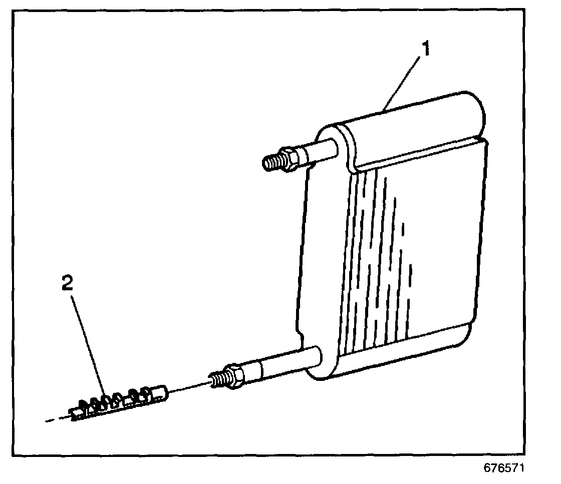
2. Remove the evaporator tube from the evaporator (1).
3. Remove the O-ring seal and discard.
4. Use the J 26549-E in order to remove the expansion (orifice) tube (2).
5. If you have difficulty removing a restricted or plugged expansion (orifice) tube, use the following procedure:
5.1.Remove as much of any impacted residue as possible.
NOTE: If the system has a pressure switch near the expansion (orifice) tube location, it should be removed prior to heating the pipe to avoid damage to switch.
IMPORTANT: DO NOT overheat the pipe.
5.2.Carefully apply heat with a heat gun (hair dryer, epoxy dryer, or equivalent) approximately 7 mm (0.25 in) from the dimples on the inlet pipe.
5.3.While applying heat, use the J 26549-E or equivalent in order to grip the expansion (orifice) tube.
5.4.Use a turning motion along with a push-pull motion in order to loosen the impacted expansion (orifice) tube.
Remove the expansion (orifice) tube.
INSTALLATION PROCEDURE
IMPORTANT: Install the shorter screen end of the expansion (orifice) tube into the evaporator first.
pic 1
1. Use the J 26549-E in order to install the expansion (orifice) tube (2).
2. Coat the new O-ring seal with 525 viscosity refrigerant oil.
3. Install the new O-ring seal.
NOTE: Refer to Fastener Notice in Service Precautions.
4. Install the evaporator tube to the evaporator (1).
Tighten
Tighten the evaporator tube to 28 N.m (21 lb ft):
5. Evacuate and recharge the A/C system. Refer to Refrigerant Recovery and Recharging.
6. Leak test the fittings components using the J 39400-A.
________________________________________
I don't know if you want them, but here are the directions for flushing the system, which may be a good idea since there was bearing damage.
_______________________________________
Subject:
Contaminated R-134a A/C Systems - Air Conditioning System Flushing Procedures and Universal In-Line A/C Filter Installation
Models:
1993-2005 Passenger Cars and Light Duty Trucks
with Air Conditioning
This bulletin is being revised to update the parts information. Please discard Corporate Bulletin Number 01-01-38-006C (Section 01 - HVAC).
GM Service Operations has worked with GM dealers to develop tools and procedures to properly flush A/C (air conditioning) systems. The recommended flushing procedure uses liquid R-134a refrigerant to perform the system flush and is the only GM approved method for system flushing. The use of alternate methods that utilize solvents has proven to be detrimental to A/C system performance and durability. Every General Motors dealer has received a J 43600 ACR 2000 Air Conditioning Service Center that has built-in A/C system flushing capabilities. Every General Motors dealer has also received a J 45268 Flush Adapter Kit to utilize the flushing capability of the J 43600 ACR 2000.
This bulletin contains a general outline of the procedure and when to perform A/C system flushing. Vehicle specific flushing information is contained in the HVAC section of SI.
A/C system flushing should NOT be routinely performed when a system failure is encountered. System flushing takes a considerable amount of time to perform and is NOT necessary on most system failures. System flushing requires prior authorization by the GM Area Service Manager (the District Service Manager in Canada) and should be performed only when one of the following conditions is found:
A desiccant bag failure.
A gross overcharge of A/C system lubricant.
The A/C system lubricant is contaminated.
A catastrophic compressor failure causing oil contamination.
A/C system flushing will remove some of the metal particles during a flush, but flushing is not completely effective in removing all metallic debris. System flushing should not be considered if removal of metallic debris is the only objective. GM Service Operations continues to strongly recommend the use of a Liquid Line Filter and a Suction Screen to control this type of system contamination and avoid repeat failures.
A/C System Flushing Procedure
Tools Required
J 43600 ACR 2000 Air Conditioning Service Center
J 45268 A/C Flush Adapter Kit J 41447 R-134a Tracer Dye or equivalent
J 41459 A/C Tracer Dye Injector or equivalent
J 42220 Universal 12V Leak Detection Lamp or equivalent
J 39400 Halogen Leak Detector or equivalent
J 44551 A/C Suction Screen Kit
J 45037 Oil Injector kit
J 45037-46 GM Universal Compressor PAG Oil (packaged as 6, 8 oz tubes)
A warm engine compartment or higher ambient temperatures as well as air flow across the heat exchangers (evaporator, accumulator and condenser) speed the refrigerant recovery time during the A/C flush procedure. Whenever possible, warm the engine prior to A/C system flushing. An external fan blowing across the condenser and running the A/C blower motor while the engine is running may be used to speed up refrigerant recovery.
Front Only A/C Systems
1. Recover the refrigerant from the vehicle.
2. Remove the expansion device (orifice tube or TXV (Thermostatic Expansion Valve)).
3. Connect the A/C lines with the orifice tube removed or install the appropriate TXV Adapter from the J 45268 A/C Flush Adapter Kit.
4. Disconnect the A/C compressor manifold (never flush through a compressor).
5. Inspect the end of the suction hose for a suction screen. Remove the suction screen using the screen remover in the J 44551 A/C Suction Screen Kit, if installed.
6. Install the appropriate A/C compressor hose assembly flush adapter(s) from kit J 45268.
7. Configure the flush adapter and hose for either a forward flush or reverse flush. Refer to the Flushing Configuration section of this bulletin.
Front/Rear (Dual Circuit) A/C Systems
Each circuit of a front/rear A/C system must be flushed separately. Flow to one circuit must be blocked with the use of a blocked orifice tube or blocked TXV. The front circuit should always be flushed first.
Front Circuit
1. Recover the refrigerant from the vehicle.
2. Remove the expansion device (orifice tube or TXV) from the front circuit.
3. Re-connect the A/C lines with the orifice tube removed or install the appropriate non-blocked (open) TXV Adapter from kit J 45268.
Important:
A blocked orifice tube is not supplied with the J 45268 Adapter kit. A blocked orifice can be made as follows: Cut the orifice tube frame and screen.
Remove enough of the frame and screen to access the end of the brass orifice tube. Seal the tube by pinching off the end of the orifice tube.
4. Remove the expansion device (orifice tube or TXV) from the rear circuit and install a plugged expansion device (orifice tube or TXV) into the rear circuit.
5. Disconnect the A/C compressor manifold.
6. Inspect the end of the suction hose for a suction screen. Remove the suction screen using the screen remover in the J 44551 A/C Suction Screen Kit, if installed.
7. Install the appropriate A/C compressor hose assembly flush adapter(s) from kit J 45268.
8. Configure the flush adapter and hose for either a forward flush or a reverse flush. Refer to the Flushing Configuration section of this bulletin.
9. Perform the flush of the front system by following the instructions supplied with the J 43600 ACR 2000.
10. Replace the plugged expansion device (orifice tube or TXV) in the rear circuit with an open expansion device (orifice tube or TXV).
11. Replace the open expansion device (TXV or orifice tube) in the front circuit with a plugged expansion device (orifice tube or TXV).
12. Flush the rear system by following the instructions supplied with the J 43600 ACR 2000.
Flushing Configuration - Forward Flush
Forward flushing (the same flow as normal system operation) is recommended for contaminated refrigerant and/or A/C system lubricant.
Important:
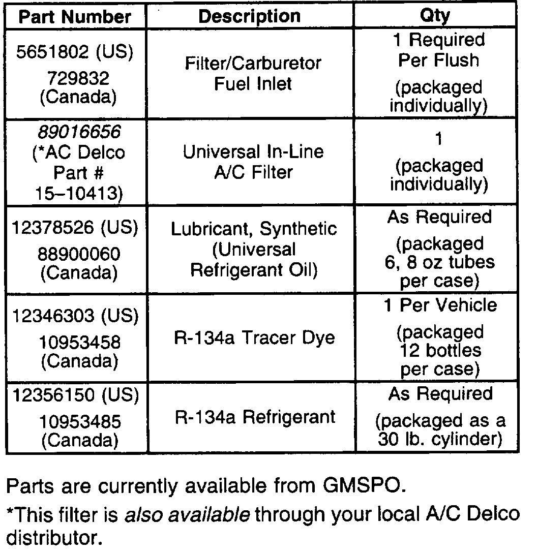
Install a new filter inside the J 45268-1 for every flush. Service the filter with GM P/N 5651802 (use P/N 729832 in Canada). Remove and discard the check valve from the filter.
Important:
Check that the J 43600 ACR 2000 has a sufficient refrigerant charge prior to the start of the flushing procedure. The J 43600 ACR 2000 must have at least 7 pounds (3.18 kgs) of refrigerant available for charging in the machine's internal storage vessel.
Important:
Always close the valve on the J 43600 ACR 2000 external refrigerant tank before starting the flushing procedure.
Follow these steps to perform the forward flush:
1. Connect the J 45268-1 flush filter adapter to the suction port of the A/C compressor hose assembly flush adapter.
2. Connect the blue hose from the J 43600 ACR 2000 to the J 45268-1 flush filter adapter.
3. Connect the red hose from the J 43600 ACR 2000 to the discharge port of the A/C compressor hose assembly flush adapter.
4. Follow the instructions supplied with the J 43600 ACR 2000 and flush the A/C system.
Flushing Configuration - Reverse Flush
Reverse flushing (the opposite flow of normal operation) is recommended for a desiccant bag failure. Always replace the accumulator after the reverse flushing procedure is complete.
Important:
Install a new filter inside the J 45268-1 for every flush. Service the filter with P/N 5651802 (in Canada, P/N 729832). Remove and discard the check valve from the filter.
Important:
Check that the J 43600 ACR 2000 has a sufficient charge prior to the start of the flushing procedure. The J 43600 ACR 2000 must have at least 7 pounds (3.18 kgs) of refrigerant available in the machine's internal storage vessel.
Important:
Always close the valve on the J 43600 external refrigerant tank before starting the flushing procedure.
Follow these steps to perform the reverse flush:
1. Connect the J 45268-1 flush filter adapter to the discharge port of the A/C compressor hose assembly flush adapter.
2. Connect the blue hose from the J 45268-1 flush filter adapter.
3. Connect the red hose to the suction port of the A/C compressor hose assembly flush adapter.
4. Follow the instructions supplied with the J 43600 ACR 2000 and flush the A/C system.
After Flushing Is Complete
Important:
Flushing will remove all the A/C system lubricant and leak detection dye from the A/C system. After a catastrophic compressor failure, it is extremely important to eliminate and/or contain the debris that may cause repeat repairs. The debris generated from a catastrophic compressor failure will be discharged into the compressor suction line, discharge line, condenser and liquid line. The use of the J 44551 Suction Screen kit DOES NOT replace the need for liquid line filters as described in the vehicle specific Service Information. A liquid line filter should be installed whenever possible, after a catastrophic compressor failure, to protect the expansion device (orifice tube or TXV) in both the front and rear systems from debris.
The J 44551 supplies your dealership with the right tools and supplies to cover the Delphi HD6, HU6 and HT6 compressors, as well as most non-Delphi compressors, for most GM applications. Delphi V5 and V7 compressors already have this screen installed in the suction port of the compressor and do not need an additional screen installed.
The J 44551 Suction Screen Kit contains three different screen sizes. Additional screen sizes are being developed. It is important to select the correct size screen that will press fit into the suction port of the compressor hose assembly. The screen should not be installed loose inside the hose assembly.
1. Insert the J 44551-6 sizing tool into the suction hose to select the correct size suction screen.
2. Insert the suction screen into the compressor end of the suction hose.
3. Select and install the correct mandrel to the J 44551-5.
4. Install the J 44551-5 screen installation tool over the end of the suction hose and the suction screen.
Important:
Correct placement of the J 44551 is critical.
5. Tighten the forcing screw of the J 44551-5. The suction screen is fully installed when the screen is flush with the end of the suction hose fitting.
6. Remove the J 44551-5 suction screen tool from the suction hose.
7. Install the J 44551-1 Suction Screen Notification Label.
8. Remove the A/C compressor.
9. Remove the A/C compressor drain plug, if equipped. Drain the A/C system lubricant from the compressor into a clean, graduated cylinder. Rotate the compressor input shaft to assist in draining the A/C system lubricant from the compressor. Measure and record the amount of A/C system lubricant removed.
10. Install the A/C compressor drain plug, if equipped.
11. Install the A/C compressor.
12. Remove the blocked orifice tube or TXV adapter (front/rear systems only).
13. Install a new orifice tube or remove the TXV adapter.
Inspect the original TXV for debris.
Clean or replace the original TXV as needed.
For front/rear systems, be sure both expansion devices (orifice tubes or TXVs) are installed.
Important:
Even after a system flush, control devices are subject to contamination and malfunction. To insure long term reliability the installation of the newly redesigned in-line A/C filter before an orifice tube or rear TXV is recommended.
Install the in-line filter on front A/C systems before the orifice tube.
Install the in-line filter on front/rear A/C systems before the "Y" in the evaporator tube.
Do not allow metal burrs to enter the evaporator tube during cutting or when removing the burrs.
Because of limited space in the engine compartment, it may be necessary to remove the system's existing orifice tube and install the orifice in the in-line filter.
14. Install a Universal In-line A/C Filter, P/N 89016656 (AC Delco P/N 15-10413). Refer to the instruction sheet included with the filter for detailed installation instructions. Re-install the suction screen if it was previously removed.
15. Look up the required amount of A/C system lubricant for the vehicle being worked on. Refer to the System Capacities table in the appropriate section of SI. Remember that after a system flush there is no lubricant in the A/C system.
16. Install the proper amount of Synthetic Lubricant (Universal Refrigerant Oil), P/N 12378526 (in Canada, P/N 88900060), into the A/C system using the J 45037 Oil Injector.
17. Add one bottle of J 41447 R-134a Tracer Dye, GM P/N 12346303 (in Canada, P/N 10953458), or the equivalent, using the J 41459 dye injector (or the equivalent).
18. Evacuate the A/C system.
19. Recharge the A/C system to the proper charge level specified for that vehicle's A/C system.
20. Verify proper A/C system operation.
21. Leak test all connections using the J 44220 Universal 12V Leak Detection Lamp, the J 39400-A Leak Detector or equivalents. Remember that the A/C system must operate for several minutes before leak dye will show a leak if one is present.
pic 2
Let me know if this helps or if you have other questions.
Take care,
Joe
Images (Click to make bigger)
Saturday, June 1st, 2019 AT 9:10 PM