Welcome to 2CarPros.
My first suspect is that the re-circulation actuator is faulty. I noted that you have a good bit of knowledge, so first I'm going to explain how to check it.
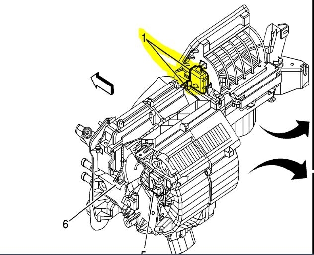
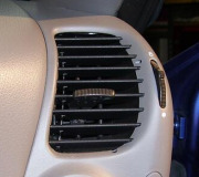
If you look at picture 1, it shows location.
_____________________________________
Here are the directions for diagnosing a fault with this system:
+++++++++++++++++++++++++++++
AIR RECIRCULATION MALFUNCTION
Air Recirculation Malfunction
Diagnostic Fault Information
Perform the Diagnostic System Check - Vehicle prior to using this diagnostic procedure. See: Vehicle > Initial Inspection and Diagnostic Overview
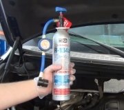
pic 2
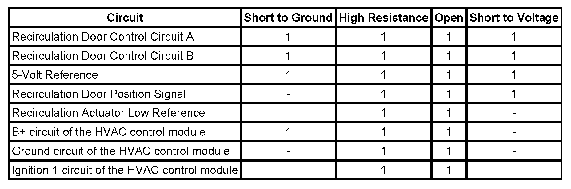
Circuit/System Description
The recirculation actuator is a 5-wire bi-directional electric motor that incorporate a feedback potentiometer. Low reference, 5-volt reference, position signal, and 2 control circuits enable the actuators to operate. The control circuits use either a 0 or 12-volt value to coordinate the actuator movement. When the actuator is at rest, both control circuits have a value of 0 volts. In order to move the actuator, the HVAC control module grounds one of the control circuits while providing the other with 12 volts. The HVAC control module reverses the polarity of the control circuits to move the actuator in the opposite direction. When the actuator shaft rotates, the potentiometer's adjustable contact changes the door position signal between 0-5 volts.
Diagnostic Aids
Inspect the recirculation door and recirculation actuator for the following:
* A misaligned recirculation actuator. Refer to Recirculation Actuator Replacement.
* Broken or binding linkages or recirculation door.
* An obstruction that prevents the recirculation actuator from operating within the full range of motion.
* Missing seals to the recirculation door.
If the above procedure does not fix the problem test the HVAC control module ignition 1 circuit for an open or high resistance.
Circuit/System Verification
1. Turn ON the ignition, with the engine OFF.
2. Place the blower motor switch at the maximum speed position.
3. Place the mode switch in the vent or panel position.
4. Place the recirculation switch in the ON position for recirculation.
5. Place the recirculation switch in the OFF position for outside air position.
The flow of air should change through the vent or panel.
Circuit/System Testing
1. Ignition OFF, disconnect the mode actuator harness connector at the recirculation actuator.
2. Ignition OFF, test for less than 1 ohm of resistance between the low reference circuit terminal E and ground.
If greater than 1 ohm, test the low reference circuit for an open/high resistance. If the circuit tests normal, replace the HVAC control module.
3. Ignition ON, test for 4.8 to 5.2 volts between the 5-volt reference circuit terminal C and ground.
If less than 4.8 volts, test the 5-volt reference circuit for a short to ground or an open/high resistance. If the circuit tests normal, replace the HVAC control module.
If greater than 5.2 volts, test the 5-volt reference circuit for a short to voltage. If the circuit tests normal, replace the HVAC control module.
4. Install a 3-amp fused jumper wire at the signal circuit terminal D, test for greater than 5 volts. Toggle the jumper wire between the low reference circuit terminal E and the 5-volt reference circuit terminal C.
If the position signal parameter is less than 5 volts, test the signal circuit for a short to voltage, or an open/high resistance. If the circuit tests normal, replace the HVAC control module.
5. Ignition ON, after 30 seconds verify that a test lamp illuminates between control circuit A terminal and B+.
If the test lamp does not illuminate, test the control circuit for a short to voltage or an open/high resistance. If the circuit tests normal, test the B+ circuit of the HVAC control module for a short to ground, high resistance, or an open. If the circuit tests normal, test the HVAC control module ground circuit for a high resistance or an open. If the circuit tests normal, replace the HVAC control module.
6. Ignition OFF, verify that a test lamp does not illuminate between control circuit terminal A terminal and B+.
If the test lamp illuminates, test the control circuit for a short to ground. If the circuit tests normal replace the HVAC control module.
7. Ignition ON, after 30 seconds verify that a test lamp illuminates between control circuit B terminal and B+.
If the test lamp does not illuminate, test the control circuit for a short to voltage or an open/high resistance. If the circuit tests normal, test the B+ circuit of the HVAC control module for a short to ground, high resistance, or an open. If the circuit tests normal, test the HVAC control module ground circuit for a high resistance or an open. If the circuit tests normal, replace the HVAC control module.
8. Ignition OFF, verify that the test lamp does not illuminate between control circuit terminal B and B+.
If the test lamp illuminates, test the control circuit for a short to ground. If the circuit tests normal replace the HVAC control module.
9. If all circuits test normal, replace the recirculation actuator.
_________________________________________
If you find that the actuator is the issue, here are the directions for replacing it.
________________________________________
RECIRCULATION ACTUATOR REPLACEMENT
Recirculation Actuator Replacement
Removal Procedure
imageOpen In New TabZoom/Print
1. Remove the instrument panel upper trim panel.
2. Disconnect the electrical connector from the recirculation actuator.
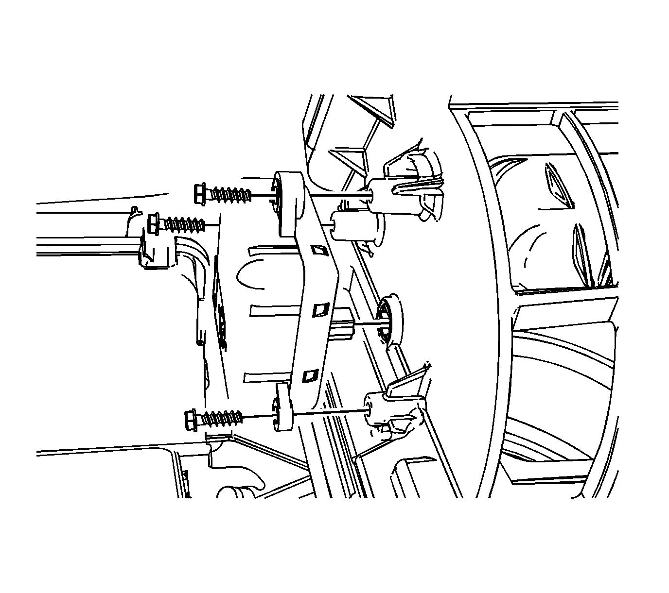
3. Remove the recirculation actuator screws from the HVAC module.
4. Remove the recirculation actuator from the HVAC module.
Installation Procedure
imageOpen In New TabZoom/Print
1. Align the recirculation actuator with the door shaft and rotate into position.
Notice: Refer to Fastener Notice.
2. Install the recirculation actuator screws to the HVAC module.
Tighten the screws to 1.5 N.m (13 lb in).
3. Connect the electrical connector to the recirculation actuator.
4. Calibrate the actuators. Refer to Actuators Recalibration. See: Vehicle > Programming and Relearning
5. Cycle the ignition and verify proper operation.
6. Install the instrument panel upper trim panel.
+++++++++++++++++++++++++++++++++++++++++++
Here are a few links you may find helpful:
https://www.2carpros.com/articles/how-to-use-a-test-light-circuit-tester
https://www.2carpros.com/articles/how-to-use-a-voltmeter
https://www.2carpros.com/articles/how-to-check-wiring
______________________________________________________
Let me know what you find or if you have other questions.
Take care,
Joe
Images (Click to make bigger)
Thursday, July 11th, 2019 AT 9:01 PM