My concern now is if you don't know the history of the van. Someone smart enough to install an R-134 adapter should have been smart enough to change the oil in the compressor.
Don't concern yourself with that oil now. You'll never see the little that circulates in the system. There is a list of how much to add for each part that is replaced, such as a metal pipe, a hose, or other component, but those are in the order of tenths of an ounce. Also, that oil doesn't get drawn out when the system is pumped into a vacuum. Unless you repaired a leak, there's no need to add oil. When you do add to a closed system, it is done at the compressor before the system is pumped. Some charging stations can add oil separately. Right after evacuating the system, the oil goes in first, then the refrigerant.
Since you already added two cans of refrigerant, there shouldn't be a lot of bubbles in the sight glass. That should be way more than enough to turn on the low-pressure cut-out switch. This might be a good time to check for leaks. Professionals use an electronic leak sniffer. The probe is held under fittings and connections because refrigerant is heavier than air and will go down from the point of the leak. A common, but elusive place to find a leak is in a lower corner of the condenser. A dark oil stain is evidence of that leak caused by corrosion. A leaking evaporator is harder to detect. The electronic probe may pick it up at a duct outlet when running the heater fan on the lowest speed. A better place to look is at the rubber hose hanging down on the passenger's side of the firewall, under the hood.
Another leak-check method is to add refrigerant with the leak detection dye. You can find that in the same small cans. When the system is empty, that dye can also be added from a very small bottle to any open connection, or through a charging port once the valve is removed.
By the way, be sure to install the black or gray plastic caps on the charging ports when you're done. Don't be surprised if either leak detection method shows a port is leaking. Those valves are only meant to hold the refrigerant in while you put the caps on. The actual sealing is done with rubber seals in the caps.
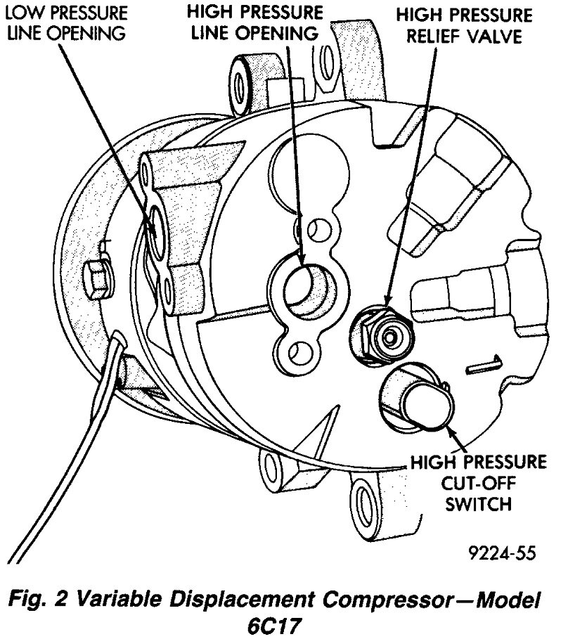
When using the dye method, first look for an eerie green stain. Common places to find it include where a rubber hose is crimped to a metal pipe, and where a metal pipe is bolted to a component. Look under the "H-valve" where the pipes go into the firewall. Also, the aluminum block where the pipes are bolted to the condenser. For small or hard-to-see leaks, use a black light to make the dye show up better. It will be bright yellow.
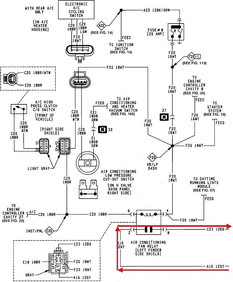
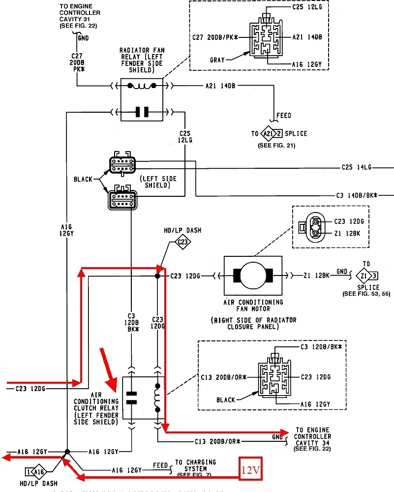
Next, we need to look at the other half of the relay. In these two diagrams, I added the red line to show the path current takes through the control side of the compressor relay. It starts at the "12V" box on the bottom of the second diagram. If you follow it to the bottom of the first diagram, you'll see it has to go through the AC fan relay. We'll have to look at that one too to be sure it is turning on. For now you may need to jump the terminals for the contacts, the gray to the dark green, 12 gauge wires, or substitute a different relay.
Side note: It's not uncommon for relays built on a phenolic board, with a metal cover crimped over them, to get moisture inside and the contacts corrode away). You might have to find a few in a salvage yard to find a nice clean one.
The circuit continues back to the second diagram, then note that it splits by splice "C23". One path feeds our compressor relay. The other line feeds the AC fan motor.
Another side note: My '88 and '89 vans have two fans in front, one for the radiator and the other for the AC condenser. My '94 and '95 models have just one fan with the condenser right in front of the radiator. Both are a lot wider than those on the older models.
According to these diagrams, your '92 model has two separate fans like in my older models. A real fast clue is if the condenser fan runs when you turn the AC on. If it does, everything is okay up to this point. If it does not, the compressor isn't going to get turned on either. It's wired that way so the compressor can't run if the fan can't cool the condenser. The compressor relay is still controlled separately, but it won't turn on if the fan relay doesn't turn on first.
Going back to that AC fan relay in the first diagram, the coil is fed 12 volts from the ignition switch. There was a common problem with the switch, and without researching it further at this time, it affected the accessory circuit including power windows, radio, and especially the heater fan. If the heater fan runs, we can skip this story for now. I think you would have noticed those other problems by now.
The other side of the relay's coil is controlled by the Engine Computer. This is where the pressure switches enter the control system and is where we'll have to go later if necessary.
Go back to the clutch relay and check for 12 volts on the 12 gauge dark green wire, or check if the AC fan is running, (passenger side fan). If it is not and there's no 12 volts, we'll have to go back to the fan relay. I'm not going to try to tell you where the AC fan relay is since there seems to be a lot of differences between your van and my drawings, so you'll have to go by the wire colors. Find the 12 gauge gray wire in the socket and check if there's 12 volts there.
While you're at it, check the voltages on all four wires, but now that has to be done with the relay plugged into its socket. Let me know how far this gets you.
Images (Click to make bigger)
Wednesday, December 7th, 2022 AT 4:54 PM