4WD wiring diagram needed

Tiny
08COLORADOPGH
  • MEMBER
  • 2008 CHEVROLET COLORADO
  • 3.7L
  • 5 CYL
  • 4WD
  • 118,000 MILES
Truck listed above is the LT model.

Does anyone have a wiring diagram for the 4wd front axle actuator and transfer case motor? Every once in a while the actuator motor works. I replaced it and still the same problem. I replaced transfer case motor and still the same. The light on 4h button blinks then goes right back to 2h. I checked transfer case fluid level and it is just below the fill plug.
Sunday, December 1st, 2019 AT 9:40 AM

19 Replies

Tiny
ASEMASTER6371
  • MECHANIC
  • 52,797 POSTS
Good afternoon,

I split it into pieces so you can see it better.

Let me know if you have any questions.

Roy
Was this
answer
helpful?
Yes
No
+1
Sunday, December 1st, 2019 AT 10:45 AM
Tiny
08COLORADOPGH
  • MEMBER
  • 14 POSTS
Thank you. This is very helpful. Do you have any ideas on why the 4wd front axle actuator will sometimes operate? I can here only the transfer case motor when the problem occurs. When the front actuator kicks in I can here the sound it makes as well as the transfer case motor.
Was this
answer
helpful?
Yes
No
-1
Sunday, December 1st, 2019 AT 12:14 PM
Tiny
ASEMASTER6371
  • MECHANIC
  • 52,797 POSTS
Check all your connections. Make sure they are clean, tight and no damage to any of the pins.

Roy
Was this
answer
helpful?
Yes
No
+2
Sunday, December 1st, 2019 AT 12:27 PM
Tiny
08COLORADOPGH
  • MEMBER
  • 14 POSTS
Will do. Thanks Roy.
Was this
answer
helpful?
Yes
No
Sunday, December 1st, 2019 AT 2:10 PM
Tiny
ASEMASTER6371
  • MECHANIC
  • 52,797 POSTS
You are welcome.

Roy
Was this
answer
helpful?
Yes
No
Sunday, December 1st, 2019 AT 2:11 PM
Tiny
08COLORADOPGH
  • MEMBER
  • 14 POSTS
Since replacing the transfer case motor did not change anything ; I disconnected the connector to the transfer case motor and connected it to the old motor and had a friend press the button to 4h. The spline gear turns back and forth left right left right. So this tells me the transfer case is not locked up. It does it when its not bolted to the transfer case. I tested both black ground wires and they are good. I have the same result for both motors. Anyone have any ideas as to what else to check?
Was this
answer
helpful?
Yes
No
Wednesday, December 4th, 2019 AT 5:11 PM
Tiny
ASEMASTER6371
  • MECHANIC
  • 52,797 POSTS
Okay, since you had the motor out and it switches back and forth, does the actuator on axle move as well?

Roy
Was this
answer
helpful?
Yes
No
+1
Wednesday, December 4th, 2019 AT 6:55 PM
Tiny
08COLORADOPGH
  • MEMBER
  • 14 POSTS
No the axle actuator does not turn. I replaced it and no change. Is it normal for the transfer case motor to turn then turn back several times real fast back and forth?
Was this
answer
helpful?
Yes
No
Wednesday, December 4th, 2019 AT 7:08 PM
Tiny
ASEMASTER6371
  • MECHANIC
  • 52,797 POSTS
Check the fuses in the first diagram I sent you for power. The one for TCCM and the front axle. If they are good, go to the actuator itself and verify those 2 powers to the actuator connector.

Roy
Was this
answer
helpful?
Yes
No
+1
Wednesday, December 4th, 2019 AT 7:14 PM
Tiny
08COLORADOPGH
  • MEMBER
  • 14 POSTS
Thanks, I will check that. Every once in a while the actuator operates and it switches to 4h. So I’m thinking the fuse is still good. Could the tccm cause this intermittent function?
Was this
answer
helpful?
Yes
No
Thursday, December 5th, 2019 AT 3:48 AM
Tiny
ASEMASTER6371
  • MECHANIC
  • 52,797 POSTS
Yes it can, but do your checks first.

Roy
Was this
answer
helpful?
Yes
No
+1
Thursday, December 5th, 2019 AT 4:08 AM
Tiny
08COLORADOPGH
  • MEMBER
  • 14 POSTS
Thanks Roy.
Was this
answer
helpful?
Yes
No
Thursday, December 5th, 2019 AT 4:49 AM
Tiny
08COLORADOPGH
  • MEMBER
  • 14 POSTS
Okay, this is going to sound strange. Last night I hooked up my scan tool to check for any codes. Right after I unplugged the scan tool and started the truck the 4wd started working fine ; all functions 4h, 4L, and 2h. I switched back and forth several times And it worked fine. I tried it this morning and it did not work ; just stays in 2h. I scanned it again and right after the scan it works again just fine. Could this be a problem with the truck’s computer?
Was this
answer
helpful?
Yes
No
Saturday, December 7th, 2019 AT 8:58 AM
Tiny
ASEMASTER6371
  • MECHANIC
  • 52,797 POSTS
Okay, the control module for the 4 wheel is accessed when you plug in the scan tool.

For some reason it is reacting to this.

Was there any codes in the system?

Roy
Was this
answer
helpful?
Yes
No
Saturday, December 7th, 2019 AT 9:09 AM
Tiny
08COLORADOPGH
  • MEMBER
  • 14 POSTS
Yes there was codes stored in the ABS history but it it could have been from before I bought the truck. I do not have any warning light in the cluster. No DTC codes either. Here are the codes that I found.
U1026 : loss of class 2 communication with ATC.

U1064 : lost communication with body control module.
The rest was abs sensor C codes.
Was this
answer
helpful?
Yes
No
Saturday, December 7th, 2019 AT 9:26 AM
Tiny
ASEMASTER6371
  • MECHANIC
  • 52,797 POSTS
Okay, below is the description of the code.

It looks like the serial data line is not communicating with the BCM which is part of the circuit.

Roy

Circuit Description

Modules connected to the class 2 serial data circuit monitor for serial data communications during normal vehicle operation. Operating information and commands are exchanged among the modules. When a module receives a message for a critical operating parameter, the module records the identification number of the module which sent the message for State of Health monitoring (Node Alive messages). A critical operating parameter is one which, when not received, requires that the module use a default value for that parameter. Once an identification number is learned by a module, it will monitor for that modules "Node Alive" message. Each module on the class 2 serial data circuit which is powered and performing functions that require detection of a communications malfunction is required to send a "Node Alive" message every 2 seconds. When no message is detected from a learned identification number for 5 seconds, a DTC U1xxx, where xxx is equal to the 3-digit identification number, is set.

A module with an internal class 2 serial data circuit malfunction or which loses power during the current ignition cycle would have a Lost Communication DTC set by other modules. The modules that can communicate will set a DTC indicating the module that cannot communicate. When no message is detected from a learned identification number for 5 seconds, a DTC U1xxx, where xxx is equal to the 3-digit identification number, is set.

Conditions for Running the DTC

Voltage supplied to the module is in the normal operating voltage range of 9-16 volts.
Diagnostic trouble codes U1300, U1301 and U1305 do not have a current status.
The vehicle power mode, ignition switch position, requires serial data communication to occur.

Conditions for Setting the DTC

A message from a learned identification number has not been detected for the past 5 seconds.

Action Taken When the DTC Sets

The module(s) is never signaled, therefore the specific subsystem(s) will not function.

Conditions for Clearing the DTC

A current DTC clears when the malfunction is no longer present.
A history DTC clears when the module ignition cycle counter reaches the reset threshold of 50, without a repeat of the malfunction.

Diagnostic Aids

Use the DTC Descriptor list above to determine the module which is not communicating.
Some modules may not have internal protection for specific voltage outputs and may open a battery positive voltage or ignition voltage source fuse. If a voltage input fuse is open and no short is found in that circuit, ensure that no module output voltage circuit is shorted to ground before replacing the module.
This diagnostic can be used for any module that should communicate with Class 2 serial data providing the vehicle is equipped with the option that uses that module.

Reference Information
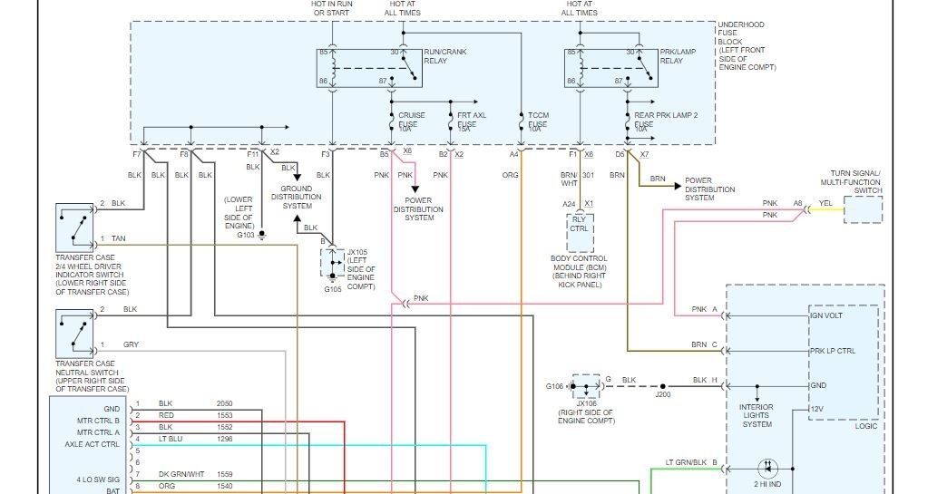
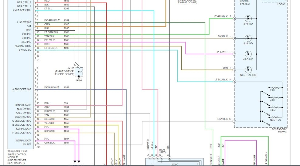
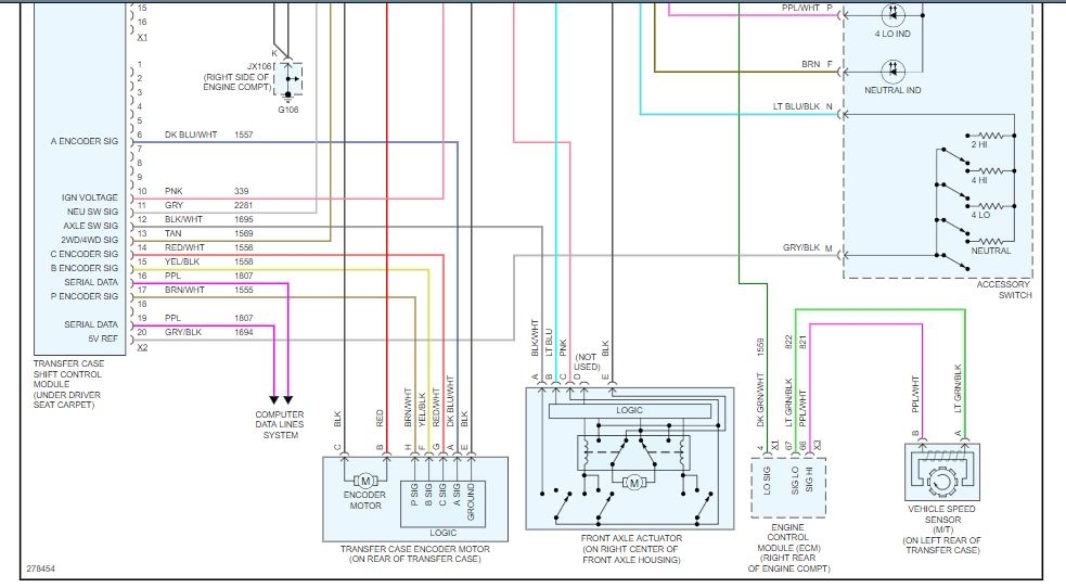
Schematic Reference

Data Communication Schematics (See: Information Bus > Electrical)
Connector End View Reference

Component Connector End Views (See: Vehicle > Connector Views)
Description and Operation

Data Link Communications Description and Operation (See: Information Bus > Components)
Electrical Information Reference

Circuit Testing (See: Vehicle > Component Tests and General Diagnostics)
Connector Repairs (See: Vehicle > Component Tests and General Diagnostics)
Testing for Intermittent Conditions and Poor Connections (See: Vehicle > Component Tests and General Diagnostics)
Wiring Repairs (See: Vehicle > Component Tests and General Diagnostics)

Scan Tool Reference

Control Module References (See: Vehicle > Programming and Relearning) for scan tool information

Circuit/System Testing

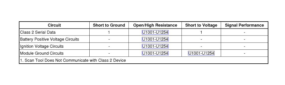
1. Ignition OFF, disconnect the harness connector of the module that is not communicating.
2. Ignition ON, verify that a test lamp illuminates between all battery positive voltage circuits and ground.

If the test lamp does not illuminate, test the circuit for a short to ground or an open/high resistance. If the circuit fuse is open, also test the positive voltage outputs of the module for a short to ground. If the circuits test normal, replace the faulty module.

3. Verify that a test lamp illuminates between all ignition voltage circuits and ground.

If the test lamp does not illuminate, test the circuit for a short to ground or an open/high resistance. If the circuit fuse is open, also test the positive voltage outputs of the module for a short to ground. If the circuits test normal, replace the faulty module.

4. Test for less than 1 ohm between the module ground circuits and ground.

If greater than the specified range, test the ground circuit for an open.

5. Test for less than 1 ohm in the class 2 serial data circuit between the non-communicating module and the module that displays the DTC.

If greater than the specified range, test the class 2 serial data circuit for open/high resistance.

6. If all circuits test normal, replace the module that is not communicating.

Repair Instructions

Perform the Diagnostic Repair Verification (See: A L L Diagnostic Trouble Codes ( DTC ) > Verification Tests) after completing the diagnostic procedure.

Control Module References (See: Vehicle > Programming and Relearning) for module replacement, setup, and programming
Was this
answer
helpful?
Yes
No
Saturday, December 7th, 2019 AT 9:42 AM
Tiny
08COLORADOPGH
  • MEMBER
  • 14 POSTS
Roy,
Could it possibly be a bad TCCM? The article that you posted says lack of communication with module. I bought a brand new TCCM today at the Chevy dealer near me. I ordered it a week ago because it was not a stock item. Does the 2008 TCCM have to be flashed or programmed ; or can I just plug it in?
Was this
answer
helpful?
Yes
No
-1
Saturday, December 7th, 2019 AT 10:14 AM
Tiny
ASEMASTER6371
  • MECHANIC
  • 52,797 POSTS
It needs to be programmed to your VIN. Once it is done, then try the system and see if it works.

Roy
Was this
answer
helpful?
Yes
No
Saturday, December 7th, 2019 AT 10:20 AM

Please login or register to post a reply.

Sponsored links