Crankshaft Position Sensor location

Tiny
LBENTON12
  • MEMBER
  • 2014 CHEVROLET MALIBU
  • 2.5L
  • 4 CYL
  • 2WD
  • AUTOMATIC
  • 95,000 MILES
Needless to say, I've replaced numerous sensors. The last code I am getting is referring to the crankshaft position sensor. I cannot find a service manual let alone afford it. I found two sources online that each say is in a different place, so I am at square one! Where can I locate this sensor? Please, please help.
Tuesday, November 5th, 2019 AT 2:38 PM

29 Replies

Tiny
ASEMASTER6371
  • MECHANIC
  • 52,797 POSTS
Good evening,

It is at the back of the motor by the flywheel.

I attached a picture and procedure.

Roy
Was this
answer
helpful?
Yes
No
+1
Tuesday, November 5th, 2019 AT 3:02 PM
Tiny
LBENTON12
  • MEMBER
  • 4 POSTS
Thank you. Does this mean that a relearn procedure is required after replacing?
Was this
answer
helpful?
Yes
No
Monday, November 18th, 2019 AT 9:05 AM
Tiny
ASEMASTER6371
  • MECHANIC
  • 52,797 POSTS
Yes, you need to perform a variation relearn after the replacement.

You need a real scan tool to perform this procedure.

I attached the procedure for you below.

Roy
Was this
answer
helpful?
Yes
No
+4
Monday, November 18th, 2019 AT 10:00 AM
Tiny
JOSE A BARRERA
  • MEMBER
  • 2 POSTS
  • 2013 CHEVROLET MALIBU
  • 2.5L
  • 6 CYL
  • AUTOMATIC
  • 129,000 MILES
Where is the crank sensor on the car listed above 2.5l ecotec? I checked tutorial photo shop and video, but I can't see anything.
Thanks
Was this
answer
helpful?
Yes
No
Wednesday, January 27th, 2021 AT 11:02 AM (Merged)
Tiny
SCGRANTURISMO
  • MECHANIC
  • 4,897 POSTS
Hello,

I have included the information that you requested in the diagrams down below. It looks like your vehicle's Crankshaft Position Sensor (CKP) is located in the back of the engine above the starter. Let us know if there is anything else we can help you with.

Thanks,
Alex
2CarPros
Was this
answer
helpful?
Yes
No
+6
Wednesday, January 27th, 2021 AT 11:02 AM (Merged)
Tiny
JOSE A BARRERA
  • MEMBER
  • 2 POSTS
Thanks for help me and resolve and fixed.
Was this
answer
helpful?
Yes
No
-2
Wednesday, January 27th, 2021 AT 11:02 AM (Merged)
Tiny
KEN L
  • MASTER CERTIFIED MECHANIC
  • 42,904 POSTS
SCWICKEDSTANG is on of our best! Nice work, we are here to help, please use 2CarPros anytime.
Was this
answer
helpful?
Yes
No
+1
Wednesday, January 27th, 2021 AT 11:02 AM (Merged)
Tiny
MOSKO2312
  • MEMBER
  • 1 POST
  • 2013 CHEVROLET MALIBU
  • 2.5L
  • 4 CYL
  • 2WD
  • AUTOMATIC
  • 113,000 MILES
I'm having quite a bit of trouble finding this sensor. From what I understand it's on the backside of the engine above the starter. I have a bore scope i'm trying to find it with to avoid taking things apart unnecessarily. Please help.
Was this
answer
helpful?
Yes
No
Wednesday, January 27th, 2021 AT 11:03 AM (Merged)
Tiny
KASEKENNY
  • MECHANIC
  • 18,907 POSTS
You are correct. It appears the starter has to come out for this one. I attached the process. Let me know if you have questions or still can't find it. You need to then perform the relearn procedure.

Thanks
Was this
answer
helpful?
Yes
No
-1
Wednesday, January 27th, 2021 AT 11:03 AM (Merged)
Tiny
MALIBU989
  • MEMBER
  • 3 POSTS
  • 2013 CHEVROLET MALIBU
  • 2.5L
  • 4 CYL
  • 2WD
  • AUTOMATIC
  • 109,000 MILES
I had a crank position sensor go bad, so I replaced it. Nineteen days later the code came back and the first new sensor had gone bad. Now I have a second new sensor and I'm trying to make sure I have a good sensor going into the car. I have test leads running from the sensor cable with T-pins to the sensor so I can check voltage across any of the three wires as I move a wrench on or off the sensor. Here are the voltages I get with each sensor I've bought when I do and don't touch the sensor to the wrench. As you can see, the two new sensors seem like the inverse of each other and the original "bad" sensor actually seems like it responds.

Original sensor:
No wrench
supply to ground: 4.98V
signal to ground: 0.71V
supply to signal: 4.24V
Touching wrench
supply to ground: 4.98V
signal to ground: 4.34V
supply to signal: 0.58V

1st New sensor:
No wrench
supply to ground: 4.97V
signal to ground: 0.03V
supply to signal: 4.92V
Touching wrench
supply to ground: 4.97V
signal to ground: 0.03V
supply to signal: 4.92V

2nd New sensor:
No wrench
supply to ground: 4.98V
signal to ground: 4.44V
supply to signal: 0.5V
Touching wrench
supply to ground: 4.98V
signal to ground: 4.44V
supply to signal: 0.5V
Was this
answer
helpful?
Yes
No
Wednesday, January 27th, 2021 AT 11:03 AM (Merged)
Tiny
CARADIODOC
  • MECHANIC
  • 33,743 POSTS
These readings are of no value and no one tests these sensors this way. The first problem is while you are correct in understanding these are magnetic sensors, touching metal to them is not what makes them work. Any time you want to generate a voltage mechanically, as in a generator, you need three things. You need a piece of wire, (a coil of wire is much more efficient), a magnet, (we use an electromagnet in a generator), and most importantly, movement between them. That's why we need to spin the generator with a belt.

Depending on the sensor's internal circuitry, you might get the signal voltage to change from one state to the other by simply holding the wrench close to the magnet, but not all are going to respond that way. Most respond to the changing magnetic field, and that is caused by the movement of something metal moving past the sensor's internal magnet.

The second problem is while these sensors develop a change in voltage from roughly 0.0 to 5.0 volts, unlike with other temperature and position sensors, voltage here is not what the computer looks at. It is looking at either the "rise time", when it switches from 0.0 to 5.0 volts, or in some applications, the "fall time", when it switches from 5.0 to 0.0 volts. Crankshaft and camshaft position sensors are only used for timing, not voltage.

If you're going to experiment with the sensor this way, it would be better to install it, then back-probe through the connector's rubber weather-pack seal and measure just the signal wire. (Never poke a hole in a wire's insulation to take a reading). While monitoring the voltage with the ignition switch on, rotate the crankshaft by hand and watch if the voltage changes. Remember though, movement is what makes these sensors work, so there is a minimum engine speed at which these will develop a reliable signal.
Was this
answer
helpful?
Yes
No
+1
Wednesday, January 27th, 2021 AT 11:03 AM (Merged)
Tiny
MALIBU989
  • MEMBER
  • 3 POSTS
Thanks for the fantastic answer Caradiodoc, this is what I was wondering but not finding an answer to in my searching so far. So to be clear, just because the old sensor had a voltage response doesn't mean it is still good, and just because my second new sensor did not doesn't mean it is bad straight out of the box.
Was this
answer
helpful?
Yes
No
Wednesday, January 27th, 2021 AT 11:03 AM (Merged)
Tiny
CARADIODOC
  • MECHANIC
  • 33,743 POSTS
That is correct. Snapon Tool Company had about a $50,000.00 engine analyzer about 12 years ago that could generate just about any sensor signal so you could see what it normally looked like, but you could learn the same thing from any text book. Not many shops bought them because of their limited value. They could have actually been of more value to a school, but in my classes we never needed to know all those details, partly because we weren't going to make a diagnosis that way, and partly because the computer is already checking those signals, and it will tell us when there is a problem with that circuit.

I forgot to mention last night that in most applications you're going to find some kind of metal disc with multiple groups of notches that are detected by the crankshaft position sensor. On some Chrysler products, for example, there will be three sets of four notches for a V-6 engine, but those only tell the computer when a pair of pistons are coming up on top dead center. You also need pulses from the camshaft position sensor to tell it which two pistons are coming up on top dead center. On other models, there could be four notches, four notches, then three notches. With the three notches, the computer figures out when piston number one is coming up on top dead center. Those systems use ignition coil packs that have one coil to fire two cylinders at the same time, one on the compression stroke, and the "waste spark" on the other cylinder on its exhaust stroke. You don't need a camshaft position sensor when the engine uses a distributor because the distributor decides which one cylinder is going to get the next spark.

The point of this sad story is when rotating the crankshaft by hand, those notches are pretty far apart, so this is a lot of work to see if the signal voltage changes. When we experiment this way with reading signals, we're more likely to do it with anti-lock brake wheel speed sensors. Those develop around 45 to 60 pulses per revolution so it's easy to read something, but here again, the exact voltage is irrelevant. Digital voltmeters are only accurate on the AC Volts scales when reading a 60 hertz sine wave. They are totally inaccurate at other frequencies, and the voltage of the signals depends on wheel speed, just like with other magnetic sensors and generators. Also, when these position sensors have three wires, meaning there's a bunch of electronic circuitry inside them, they develop square=wave signals. Digital meters do not like anything other than nice smooth sine waves. The only meters that hold any value are those that can read frequency, but that still has no meaning unless you can read all four wheels at the same time with four meters. That is what the computer does, and we can see that with a scanner. The only value in testing the signal with a meter is to know whether you have something or nothing. When you have something, there is still a lot more the computer checks for to know when to set a fault code.

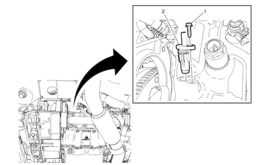
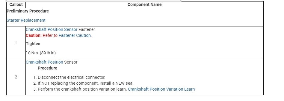
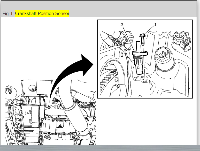
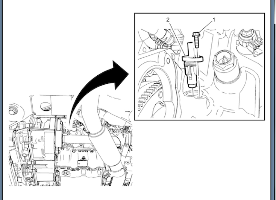
To get back to your original problem, one thing I forgot to mention is for some of these magnetic sensors, the air gap can be critical. When you have multiple repeat failures, it could just be bad luck with one replacement brand, or you may need to look for a mechanical issue related to that sensor. Examples of mechanical problems include that air gap, or a broken tone ring or whatever metal piece the sensor is detecting. Most crankshaft position sensors have a type of mounting bracket that you just bolt on and you're done. A few have slotted mounting holes to allow for adjustment. When you see those slotted holes, there is a procedure to set that air gap. I had a dozen that I was too smart to have to follow that procedure. The 13th one came back on a tow truck two weeks later with a fault code for that sensor, and a crank / no-start condition. I replaced the sensor, but setting the air gap as instructed probably would have solved the problem. So much for being smarter than the engineers.
Was this
answer
helpful?
Yes
No
+1
Wednesday, January 27th, 2021 AT 11:03 AM (Merged)
Tiny
KEN L
  • MASTER CERTIFIED MECHANIC
  • 42,904 POSTS
If I can jump in here, did you use a AC Delco sensor? If not that might be the problem, aftermarket sensors are not as good and fail. Here is the sensor location in case someone that visits this post can understand what we are talking about. Check out the diagrams (Below). Please let us know what you find. We are interested to see what it is.
Was this
answer
helpful?
Yes
No
Wednesday, January 27th, 2021 AT 11:03 AM (Merged)
Tiny
MALIBU989
  • MEMBER
  • 3 POSTS
Ken, yes both sensors I've tried are AC Delco brand. The first was a #12627185 (same as the original the car came with) and it failed after 19 days. Then I read this sensor model was discontinued and replaced by #12674702, so this is what is in the car now. So far so good but it's only been a day. I'll keep you posted if this fails also or not.
Was this
answer
helpful?
Yes
No
Wednesday, January 27th, 2021 AT 11:03 AM (Merged)
Tiny
AM84PM
  • MEMBER
  • 15 POSTS
  • 2013 CHEVROLET MALIBU
  • 2.5L
  • 4 CYL
  • 2WD
  • AUTOMATIC
  • 74,000 MILES
Hello, if I change the crankshaft position sensor for my car listed above, do I have to do the relearning or I can ignore relearning?

Thanks.
Was this
answer
helpful?
Yes
No
Wednesday, January 27th, 2021 AT 11:03 AM (Merged)
Tiny
KEN L
  • MASTER CERTIFIED MECHANIC
  • 42,904 POSTS
Please do, we are interested to see what it is.
Was this
answer
helpful?
Yes
No
Wednesday, January 27th, 2021 AT 11:03 AM (Merged)
Tiny
STEVE W.
  • MECHANIC
  • 12,977 POSTS
It must be reset using a scan tool or it will set a code P0315. What is the reason you are replacing the sensor? If the engine runs and has not set a misfire code or is stalling when it heats up it may not be the sensor that is the issue.
Was this
answer
helpful?
Yes
No
Wednesday, January 27th, 2021 AT 11:03 AM (Merged)
Tiny
AM84PM
  • MEMBER
  • 15 POSTS
Hello Steve, the whole story can be found here:

https://www.2carpros.com/questions/cranks-but-doesnt-start-randomly-happens/r/991663087

Was this
answer
helpful?
Yes
No
Wednesday, January 27th, 2021 AT 11:03 AM (Merged)
Tiny
STEVE W.
  • MECHANIC
  • 12,977 POSTS
Intermittent faults could be the sensor or the wiring to it. Because it's an easy part to get to I'd change it out and check the connector real good.
Was this
answer
helpful?
Yes
No
+1
Wednesday, January 27th, 2021 AT 11:03 AM (Merged)

Please login or register to post a reply.

Sponsored links