It could be a few things. The first thing to check is the brake fluid level. If it is low, check under the vehicle and near the wheels for leaks. If none are found, then chances are it is the brake master cylinder.
Take a look through this link:
https://www.2carpros.com/articles/brake-pedal-goes-to-the-floor
If you find it is the master cylinder, here is a link that shows in general how it is replaced.
https://www.2carpros.com/articles/how-to-replace-a-brake-master-cylinder
Here are the directions specific to your vehicle. The pics below correlate with the directions.
_________________________
2007 Toyota Camry L4-2.4L (2AZ-FE)
Removal and Replacement
Vehicle Brakes and Traction Control Hydraulic System Brake Master Cylinder Service and Repair Removal and Replacement
REMOVAL AND REPLACEMENT
BRAKE MASTER CYLINDER
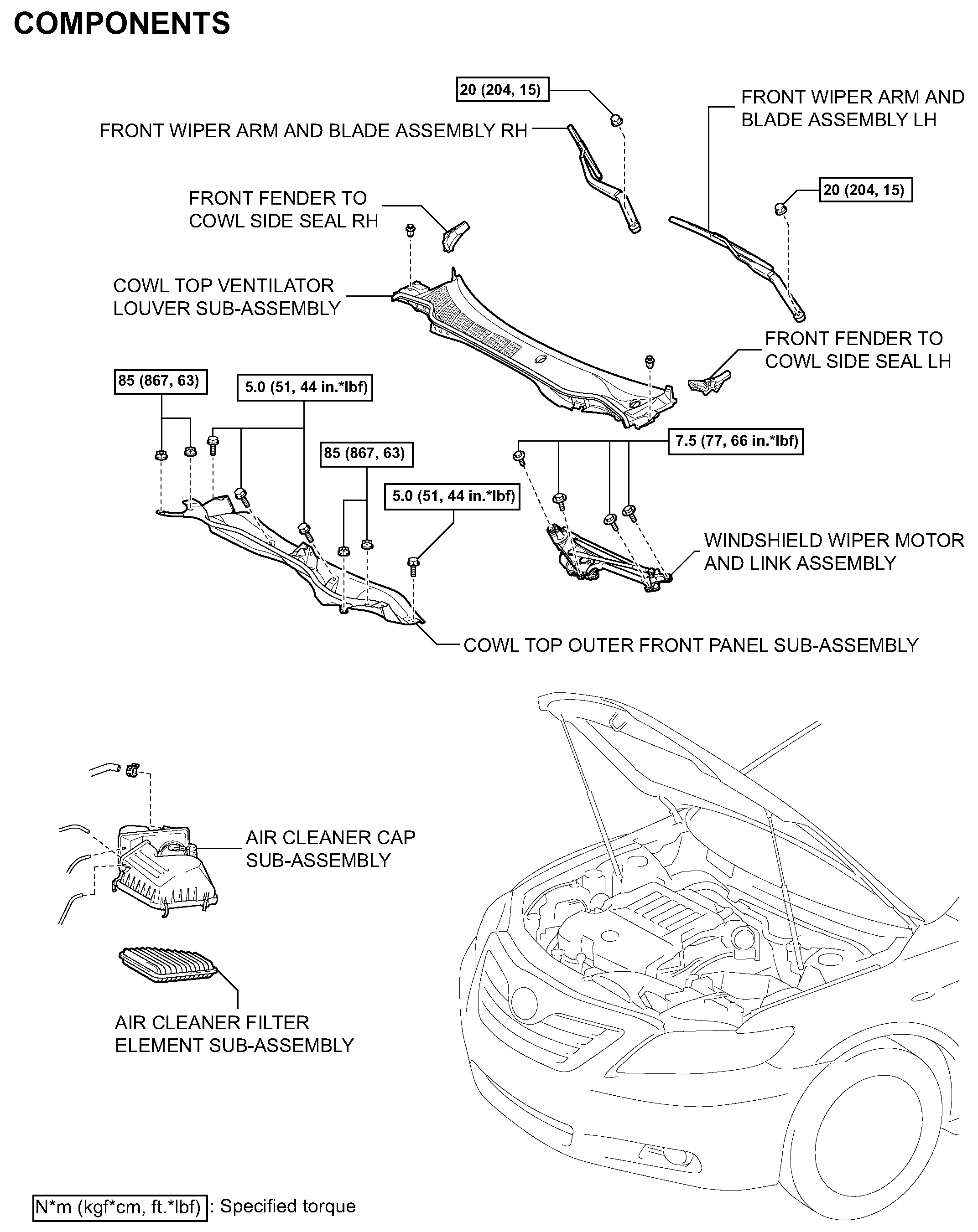
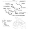
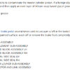
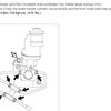
COMPONENTS (Part 1)
pic 1
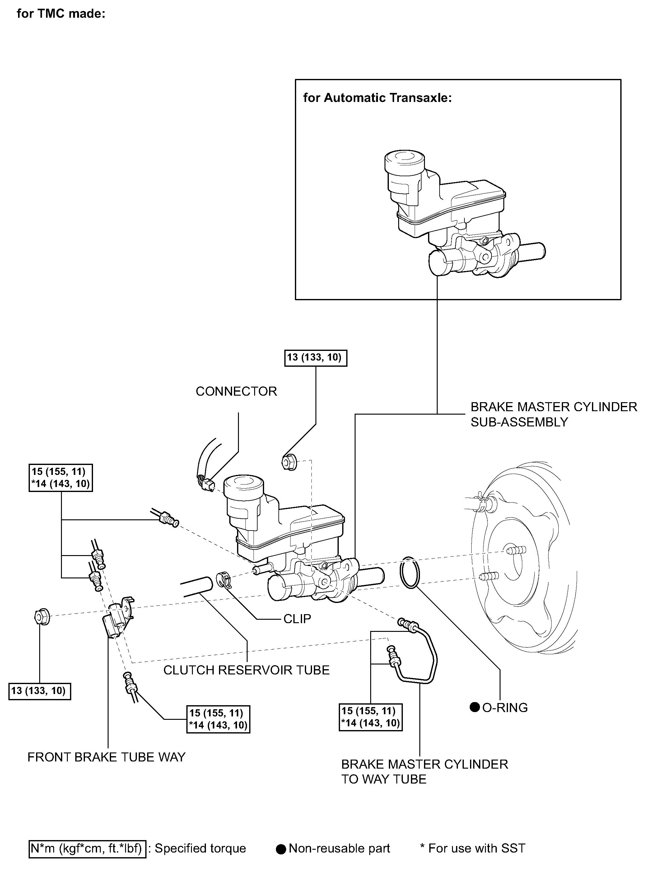
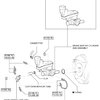
COMPONENTS (Part 2)
pic 2
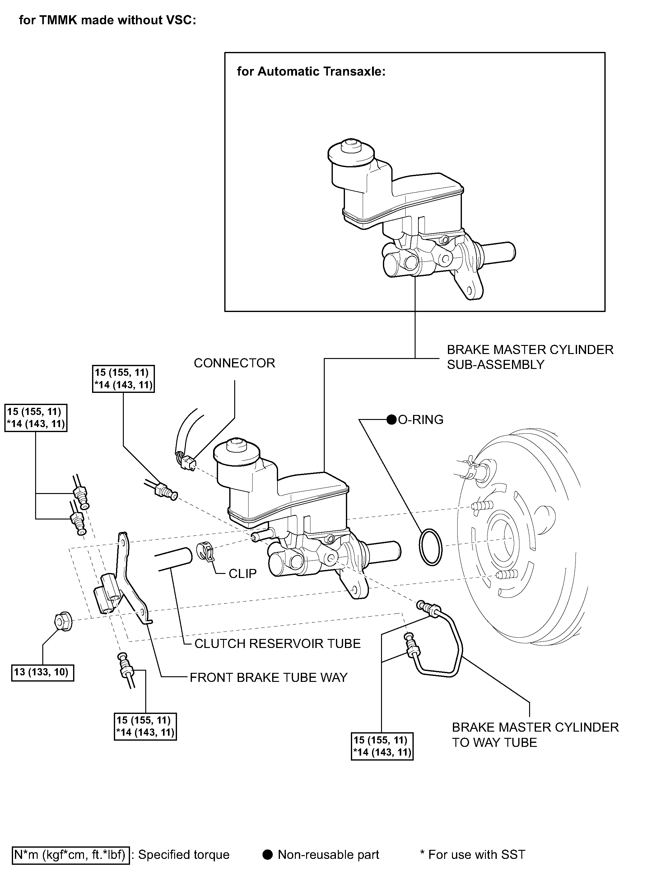
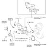
COMPONENTS (Part 3)
pic 3
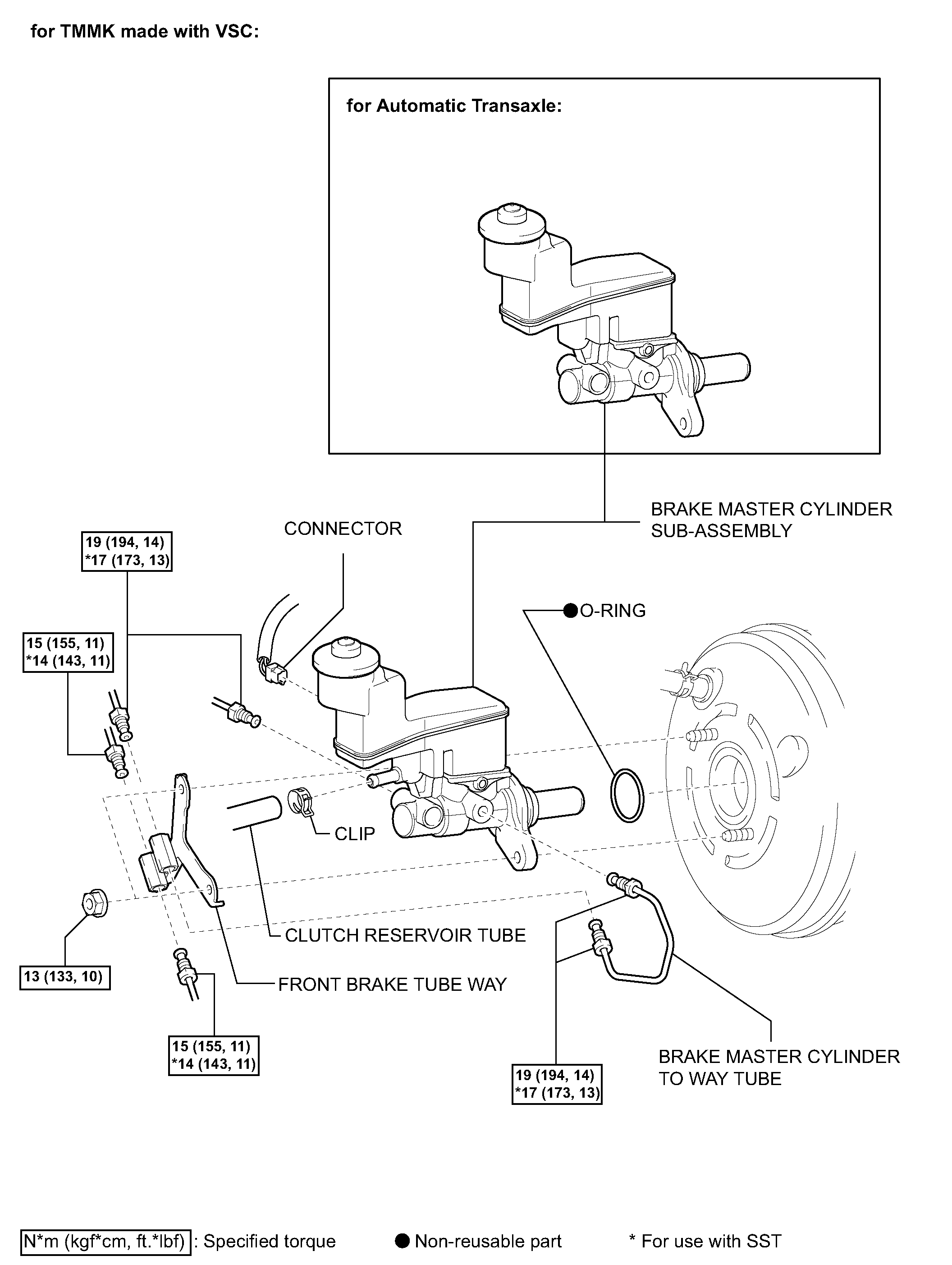
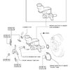
COMPONENTS (Part 4)
pic 4
REMOVAL
NOTICE: The structure of the master cylinder allows the piston to pop out, so observe the following:
(a) for TMC made:
(1) The master cylinder requires careful handling. Do not allow the master cylinder to receive any impact, such as from being dropped. Do not reuse a master cylinder that has been dropped.
(2) Do not scratch or damage the circumference of the piston. For the seal to function correctly, all sliding surfaces must not have any damage.
(3) Do not pull out the master cylinder piston.
(4) Make sure to release the vacuum from the brake booster (by removing a vacuum hose, etc.) before removing the master cylinder from the brake booster.
(5) When installing the master cylinder, remove the protectors for the piston and the discharge port.
(6) Apply the supplied grease to the outer diameter of the piston and the inner diameter of the brake booster.
(b) for TMMK made:
(1) Do not hold the master cylinder by the piston. (Hold the master cylinder by its body or its reservoir while transporting it.)
(2) Do not pull out the master cylinder piston.
(3) Do not strike or pinch the master cylinder piston, and do not cause any damage to the master cylinder piston by any other means.
(4) Make sure to release the vacuum from the brake booster before removing the master cylinder from the brake booster.
(5) When installing the master cylinder to the brake booster, or when removing the master cylinder from the brake booster, make sure that the master cylinder is kept horizontal or its tip faces downward (the piston faces upward) to prevent the master cylinder piston from falling off.
(6) Do not allow any foreign objects to contaminate the master cylinder piston. If a foreign object gets on the piston, remove it by using a shop rag or a piece of cloth and then apply an even layer of lithium soap based glycol grease around the circumference (sliding part) of the piston
(7) Do not use any other type of grease.
1. DRAIN BRAKE FLUID
NOTICE:
- Stop the engine and depress the brake pedal several times until no vacuum is left in the brake booster.
- If the brake fluid leaks onto any painted surface, wash off or remove the brake fluid completely.
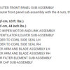
2. REMOVE AIR CLEANER CAP SUB-ASSEMBLY
3. REMOVE AIR CLEANER FILTER ELEMENT SUB-ASSEMBLY
4. REMOVE FRONT WIPER ARM AND BLADE ASSEMBLY LH
5. REMOVE FRONT WIPER ARM AND BLADE ASSEMBLY RH
6. REMOVE FRONT FENDER TO COWL SIDE SEAL LH
7. REMOVE FRONT FENDER TO COWL SIDE SEAL RH
8. REMOVE COWL TOP VENTILATOR LOUVER SUB-ASSEMBLY
9. REMOVE WINDSHIELD WIPER MOTOR AND LINK ASSEMBLY
pic 5
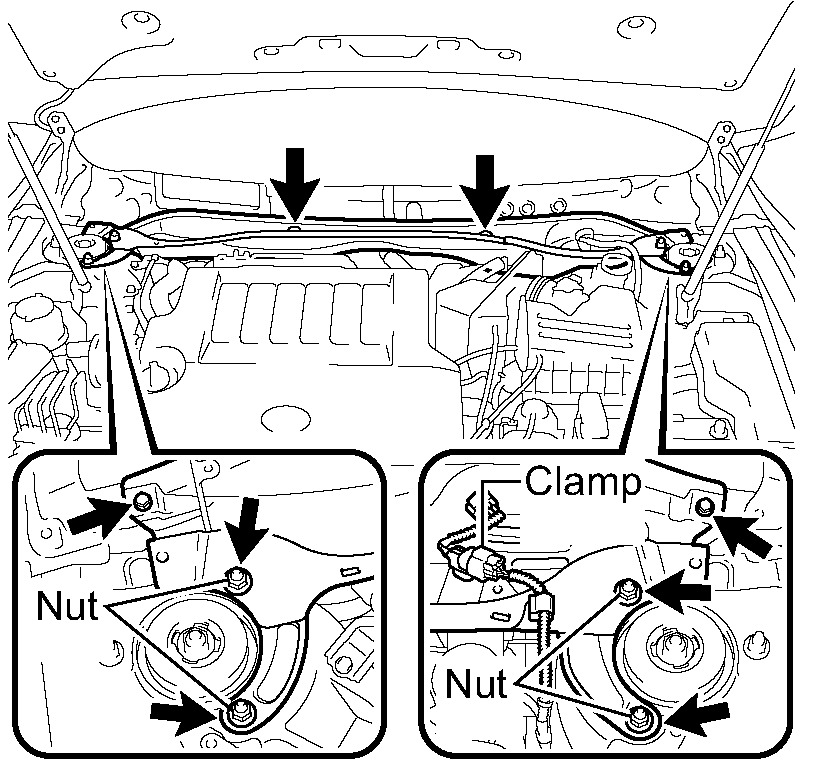
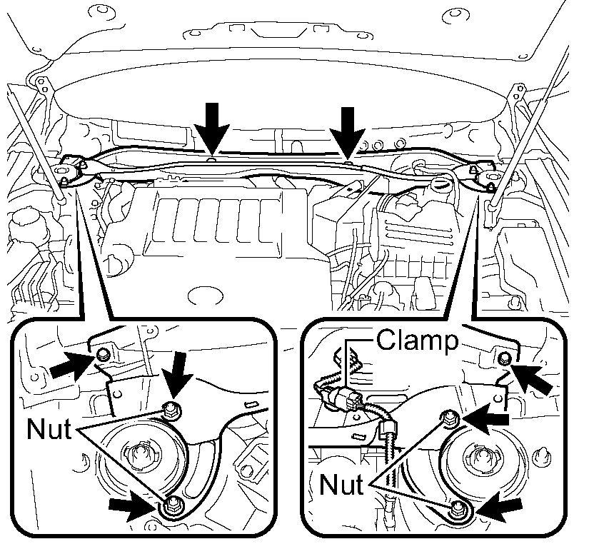
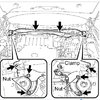
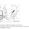
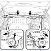
10. REMOVE COWL TOP OUTER FRONT PANEL SUB-ASSEMBLY
(a) Disengage the clamp.
(b) Remove the 4 nuts, the 4 bolts and the cowl top outer front panel sub-assembly.
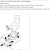
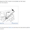
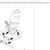
11. DISCONNECT CLUTCH RESERVOIR TUBE (for Manual Transaxle)
(a) Move the clip and disconnect the clutch reservoir tube from the brake master cylinder sub-assembly.
pic 6
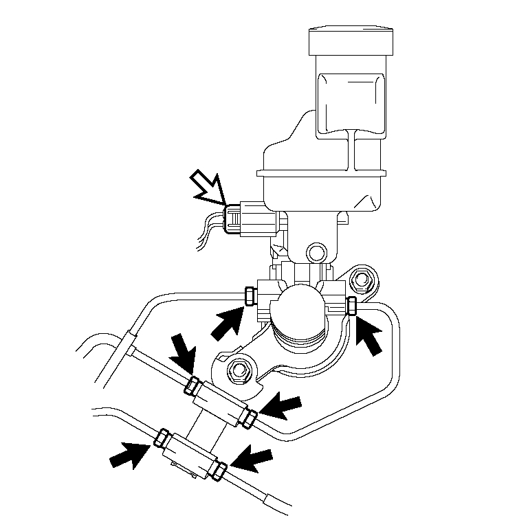
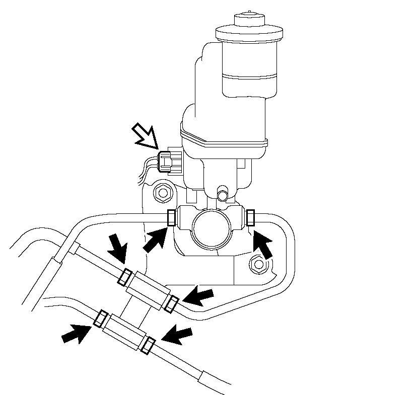
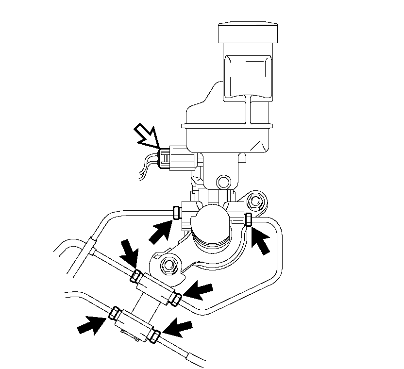
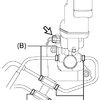
12. REMOVE BRAKE MASTER CYLINDER SUB-ASSEMBLY (for TMC Made)
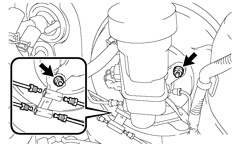
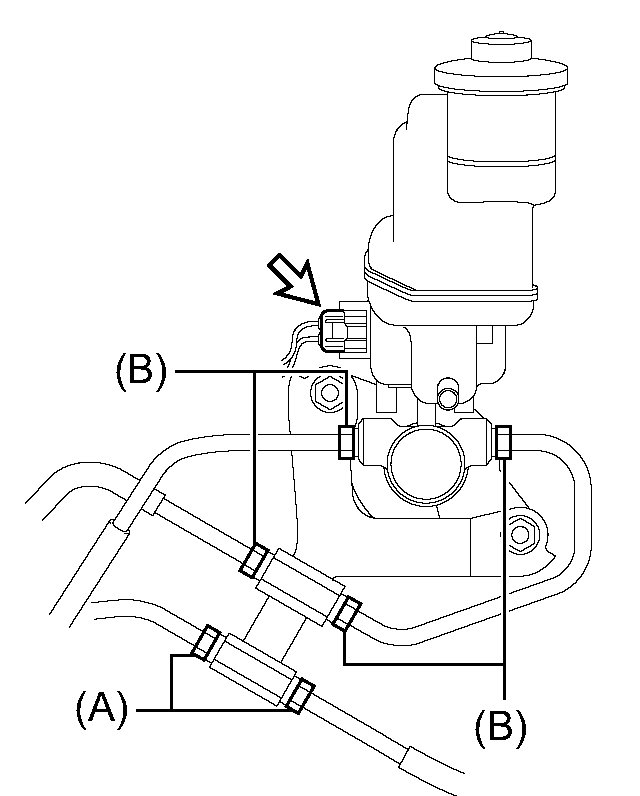
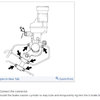
(a) Disconnect the connector.
pic 7
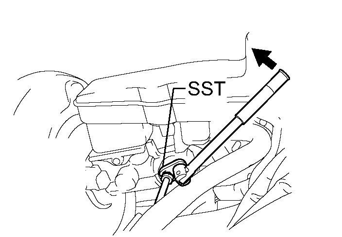
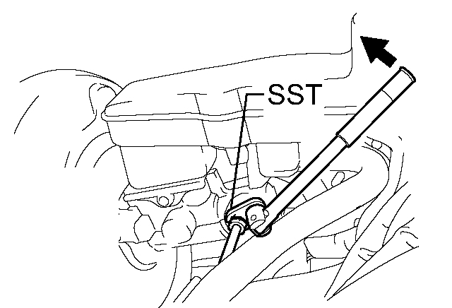
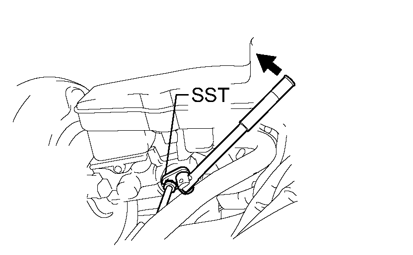
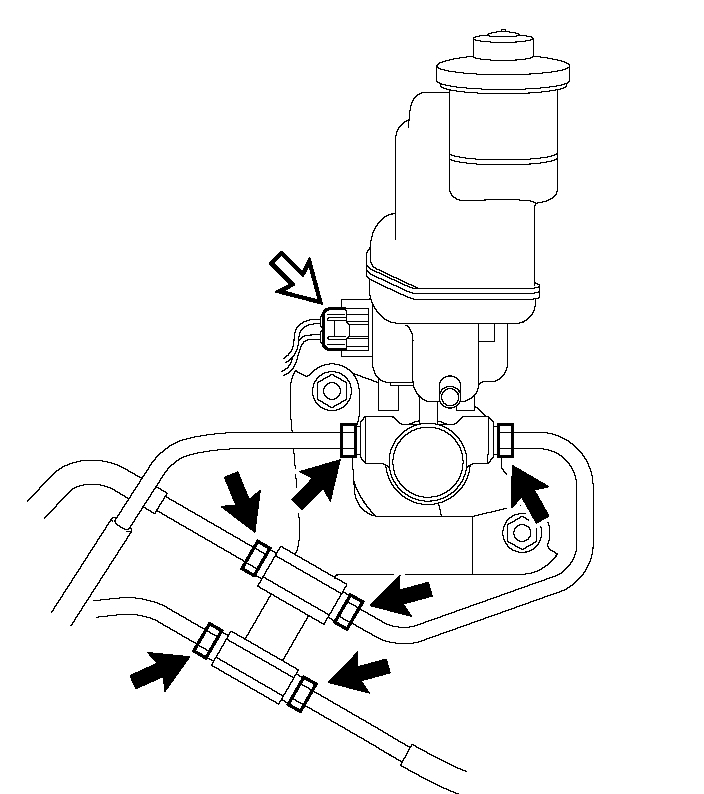
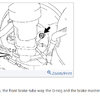
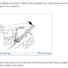
(b) Using SST, disconnect the 6 brake lines and remove the brake master cylinder to way tube.
SST 09023-00101
pic 8
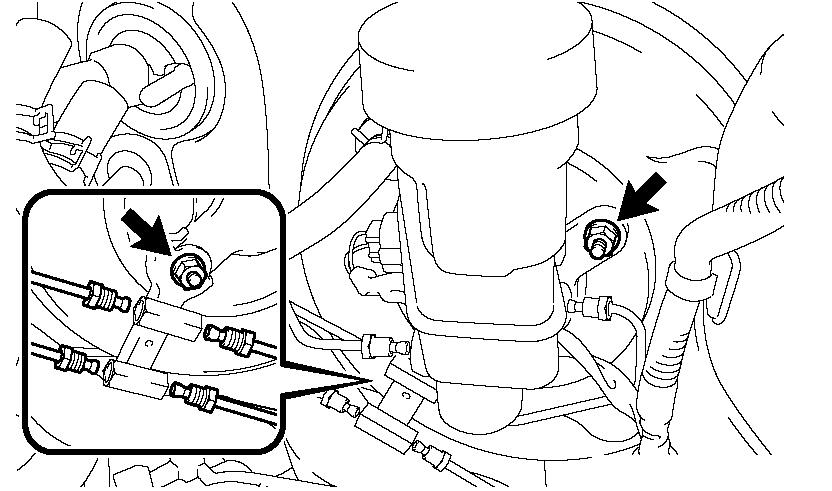
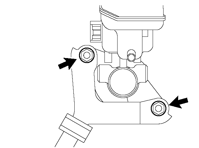
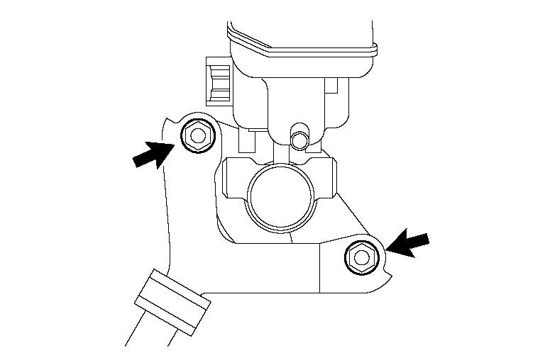
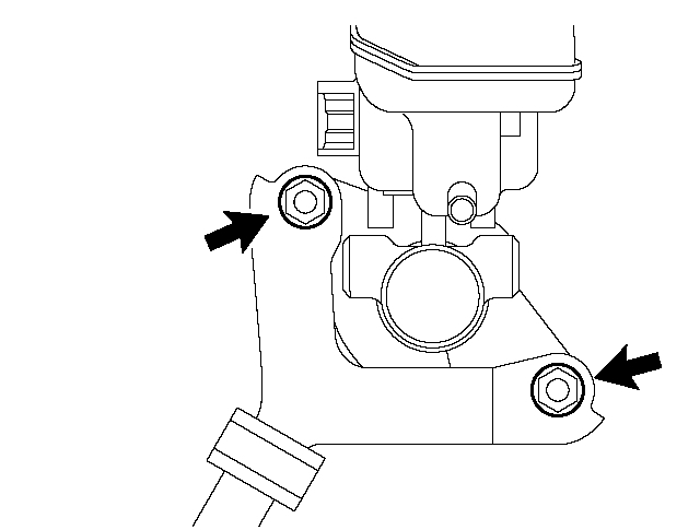
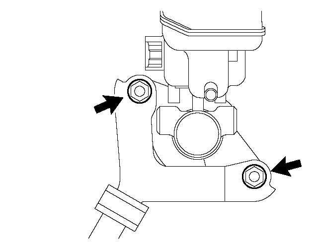
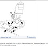
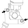
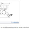
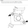
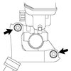
(c) Remove the 2 nuts, the front brake tube way, the O-ring and the brake master cylinder sub-assembly.
pic 9
13. REMOVE BRAKE MASTER CYLINDER SUB-ASSEMBLY (for TMMK Made without VSC)
(a) Disconnect the connector.
pic 10
(b) Using SST, disconnect the 6 brake lines and remove the brake master cylinder to way tube.
SST 09023-00101
pic 11
(c) Remove the 2 nuts, the front brake tube way, the O-ring and the brake master cylinder sub-assembly.
pic 12
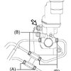
14. REMOVE BRAKE MASTER CYLINDER SUB-ASSEMBLY (for TMMK Made with VSC)
(a) Disconnect the connector.
pic 13
(b) Using SST, disconnect the 6 brake lines and remove the brake master cylinder to way tube.
SST 09023-38200, 09023-00101
pic 14
(c) Remove the 2 nuts, the front brake tube way, the O-ring and the brake master cylinder sub-assembly.
INSTALLATION
pic 15
1. INSTALL BRAKE MASTER CYLINDER SUB-ASSEMBLY (for TMC Made)
(a) Install the O-ring, the brake master cylinder sub-assembly and the front brake tube way with the 2 nuts.
Torque: 13 Nm (133 kgf-cm, 10 ft. lbs.)
pic 16
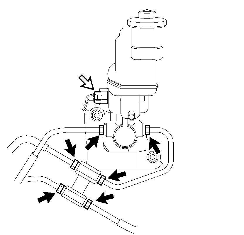
(b) Connect the connector.
(c) Install the brake master cylinder to way tube and temporarily tighten the 6 brake lines.
pic 17
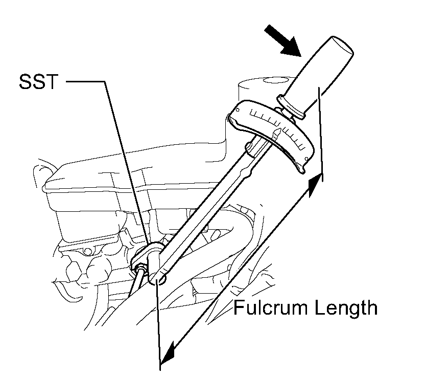
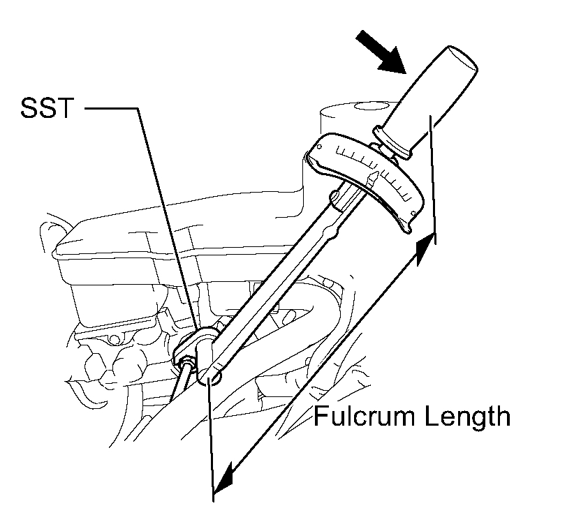
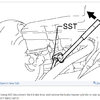
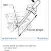
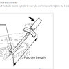
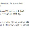
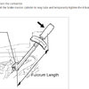
(d) Using the SST, fully tighten the 6 brake lines.
SST 09023-00101
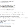
Torque:
without SST 15 Nm (155 kgf-cm, 11 ft. lbs.)
with SST 14 Nm (143 kgf-cm, 10 ft. lbs.)
NOTICE:
- Use a torque wrench with a fulcrum length of 300 mm (11.81 inch).
- This torque value is effective when SST is parallel to a torque wrench.
pic 18
2. INSTALL BRAKE MASTER CYLINDER SUB-ASSEMBLY (for TMMK Made without VSC)
(a) Install the O-ring, the brake master cylinder sub-assembly and the front brake tube way with the 2 nuts.
Torque: 13 Nm (133 kgf-cm, 10 ft. lbs.)
pic 19
(b) Connect the connector.
(c) Install the brake master cylinder to way tube and temporarily tighten the 6 brake lines.
pic 20
(d) Using the SST, fully tighten the 6 brake lines.
SST 09023-00101
Torque:
without SST 15 Nm (155 kgf-cm, 11 ft. lbs.)
with SST 14 Nm (143 kgf-cm, 10 ft. lbs.)
NOTICE:
- Use a torque wrench with a fulcrum length of 300 mm (11.81 inch).
- This torque value is effective when SST is parallel to a torque wrench.
pic 21
3. INSTALL BRAKE MASTER CYLINDER SUB-ASSEMBLY (for TMMK Made with VSC)
(a) Install the O-ring, the brake master cylinder sub-assembly and the front brake tube way with the 2 nuts.
Torque: 13 Nm (133 kgf-cm, 10 ft. lbs.)
pic 22
(b) Connect the connector.
(c) Install the brake master cylinder to way tube and temporarily tighten the 6 brake lines.
pic 23
(d) Using the SST, fully tighten the 6 brake lines.
SST 09023-00101, 09023-38200
Torque:
(A) without SST 15 Nm (155 kgf-cm, 11 ft. lbs.)
(A) with SST 14 Nm (143 kgf-cm, 10 ft. lbs.)
(B) without SST 19 Nm (194 kgf-cm, 14 ft. lbs.)
(B) with SST 17 Nm (173 kgf-cm, 13 ft. lbs.)
NOTICE:
- Use a torque wrench with a fulcrum length of 300 mm (11.81 inch).
- This torque value is effective when SST is parallel to a torque wrench.
4. CONNECT CLUTCH RESERVOIR TUBE (for Manual Transaxle)
(a) Connect the clutch reservoir tube to the brake master cylinder sub-assembly and move the clip.
5. FILL RESERVOIR WITH BRAKE FLUID
6. BLEED CLUTCH PIPE LINE (for Manual Transaxle)
7. BLEED MASTER CYLINDER
8. BLEED BRAKE LINE
9. BLEED BRAKE ACTUATOR ASSEMBLY (w/ VSC)
10. INSPECT FLUID LEVEL IN RESERVOIR
11. INSPECT FOR BRAKE FLUID LEAKAGE
pic 24
12. INSTALL COWL TOP OUTER FRONT PANEL SUB-ASSEMBLY
(a) Install the cowl top outer front panel sub-assembly with the 4 nuts, the 4 bolts and the clamp.
Torque:
Nut 85 Nm (867 kgf-cm, 63 ft. lbs.)
Bolt 5.0 Nm (51 kgf-cm, 44 inch lbs.)
13. INSTALL WINDSHIELD WIPER MOTOR AND LINK ASSEMBLY
14. INSTALL COWL TOP VENTILATOR LOUVER SUB-ASSEMBLY
15. INSTALL FRONT FENDER TO COWL SIDE SEAL LH
16. INSTALL FRONT FENDER TO COWL SIDE SEAL RH
17. INSTALL FRONT WIPER ARM AND BLADE ASSEMBLY LH
18. INSTALL FRONT WIPER ARM AND BLADE ASSEMBLY RH
19. INSTALL AIR CLEANER FILTER ELEMENT SUB-ASSEMBLY
20. INSTALL AIR CLEANER CAP SUB-ASSEMBLY
________________________________
I hope this helps. Let me know if you have other questions
Take care and God Bless,
Joe
Images (Click to make bigger)
Friday, March 5th, 2021 AT 10:50 AM