WHEEL BEARING/HUB REPLACEMENT - FRONT
NOTE: Avoid tool contact to the outer constant velocity boot seal when
removing the wheel bearing mounting bolts. Failure to observe this
notice may result in damage to the CV boot.
Removal Procedure
Raise and support the vehicle. Refer to Lifting and Jacking the Vehicle in General
Information.
1.
Remove the tire and wheel assembly. Refer to Tire and Wheel Removal and Installation (5
Lug Wheel) or Tire and Wheel Removal and Installation (4 Lug wheel) in Tires and
Wheels.
2.
Remove the wheel drive shaft nut. Refer to Wheel Drive Shaft Replacement in Wheel Drive
Shafts.
3.
Without disconnecting the hydraulic brake flex hose, remove and support the front brake caliper
and bracket as an assembly abd remove the front brake rotor. Refer to Brake Rotor
Replacement - Front in Disc Brakes.
4.
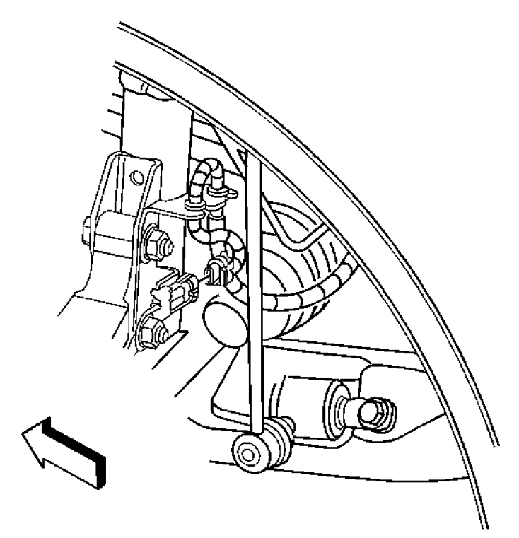
Fig. 13: Locating Wheel Bearing/Hub Spacer
Courtesy of GENERAL MOTORS CORP.
Remove the 3 wheel bearing/hub assembly mounting bolts. 7.
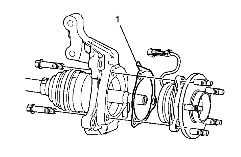
IMPORTANT: Take note of the orientation of the wheel bearing/hub spacer (1)
before removal.
Remove the wheel bearing/hub assembly and spacer (1) from the steering knuckle and wheel
drive shaft.
8.Fig. 14: Locating Wheel Bearing/Hub Spacer
Courtesy of GENERAL MOTORS CORP.
Install the wheel bearing/hub assembly and spacer (1) to the steering knuckle and wheel drive
shaft. Position the spacer as noted prior to removal.
1.
NOTE: This is a self-retaining fastener joint that does not require thread
locking compounds. Do not attempt to clean the threads with a
standard tap. If a standard tap is used, damage to the joint threads
will occur.
NOTE: Refer to Fastener Notice in Cautions and Notices.
Install the wheel bearing/hub assembly mounting bolts. Tighten the bolts evenly to draw the
bearing assembly to the steering knuckle, then tighten the bolts to specifications.
2.
Tighten: Tighten the bolts to 115 N.m (85 lb ft).Install the wheel speed sensor jumper connector to the harness retaining bracket on the strut, if
equipped with ABS.
3.
Connect the electrical connector to the wheel speed sensor jumper, if equipped with ABS. 4.Install the brake rotor abd install the brake caliper and bracket as an assembly. Refer to Brake
Rotor Replacement - Front in Disc Brakes.
5.
Install the wheel drive shaft nut. Refer to Wheel Drive Shaft Replacement in Wheel Drive
Shafts.
6.
Install the tire and wheel assembly. Refer to Tire and Wheel Removal and Installation (5
Lug Wheel) or Tire and Wheel Removal and Installation (4 Lug wheel) in Tires and
Wheels.
7.
Lower the vehicle. 8.
Images (Click to enlarge)
Dec 4, 2010 at 4:37 PM