Hi,
Here are the directions for replacement. It requires removal of the fuel tank. If you need help with that, let me know. The attached pics correlate with the directions.
__________________________________________________
2005 Nissan-Datsun Truck Xterra 2WD V6-4.0L (VQ40)
Procedures
Vehicle Powertrain Management Fuel Delivery and Air Induction Fuel Pump Service and Repair Procedures
PROCEDURES
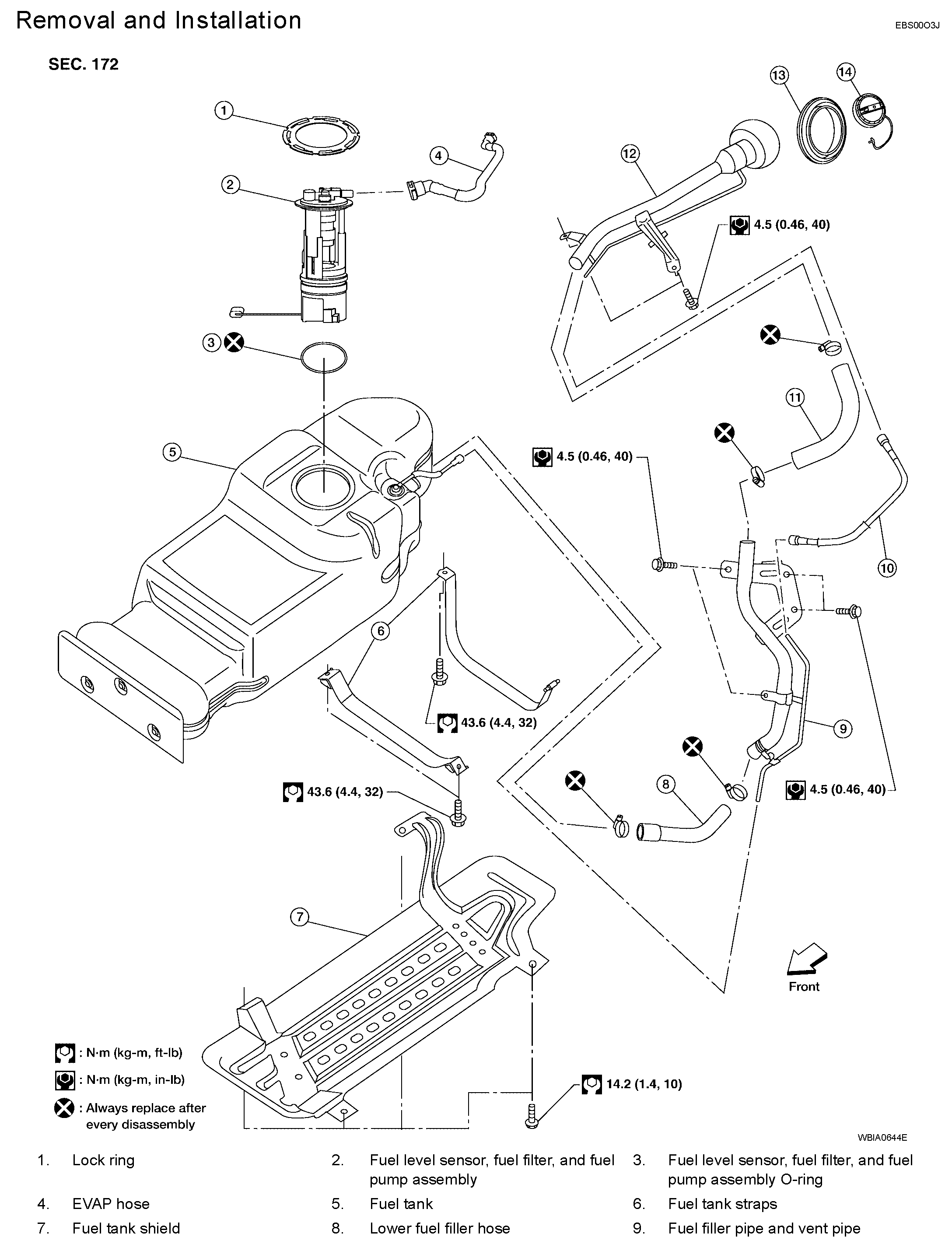
FUEL LEVEL SENSOR UNIT, FUEL FILTER AND FUEL PUMP ASSEMBLY
pic 1
Removal and Installation
REMOVAL
WARNING: Follow the "General Precautions" before working on the fuel system. Refer to "General Precautions".
1. Remove the fuel filler cap to release the pressure from inside the fuel tank.
2. Remove the LH rear wheel and tire. Refer to "Rotation".
pic 2
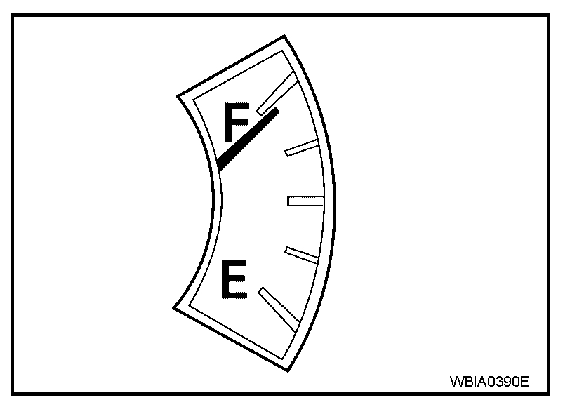
3. Check the fuel level on level gauge. If the fuel gauge indicates more than the level as shown (full or almost full), drain the fuel from the fuel tank until the fuel gauge indicates the level as shown, or less.
NOTE: Fuel will be spilled when removing the fuel level sensor, fuel filter, and fuel pump assembly for the fuel level is above the fuel level sensor, fuel filter, and fuel pump assembly fuel tank opening.
- As a guide, the fuel level reaches the fuel gauge position as shown, or less, when approximately 15 l (4 US gal, 3 1/4 Imp gal) of fuel are drained from the fuel tank.
- If the fuel pump does not operate, use the following procedure to drain the fuel to the specified level.
a. Insert a suitable hose of less than 15 mm (0.59 in) diameter into the fuel filler pipe through the fuel filler opening to drain the fuel from fuel filler pipe.
b. Disconnect the fuel filler hose from the fuel filler pipe.
c. Insert a suitable hose into the fuel tank through the fuel filler hose to drain the fuel from the fuel tank.
4. Release the fuel pressure from the fuel lines. Refer to "FUEL PRESSURE RELEASE".
5. Disconnect the battery negative terminal.
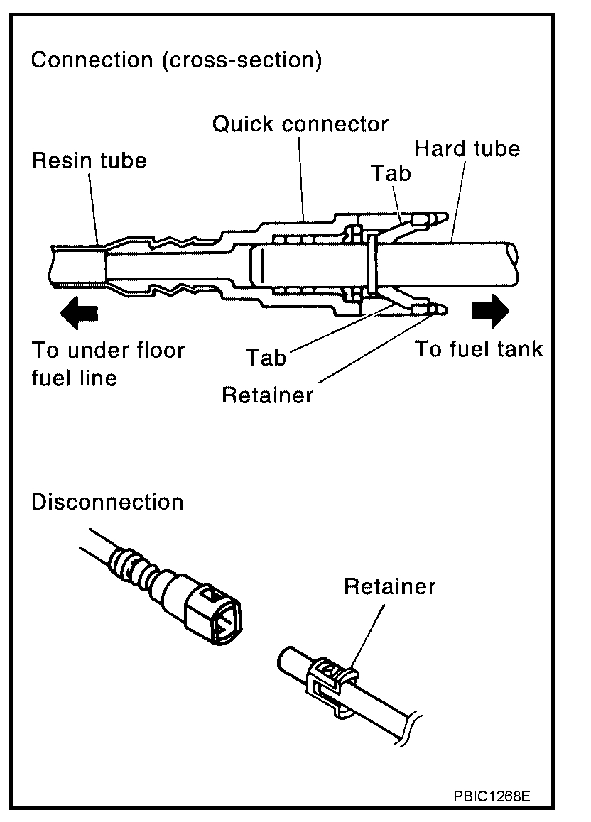
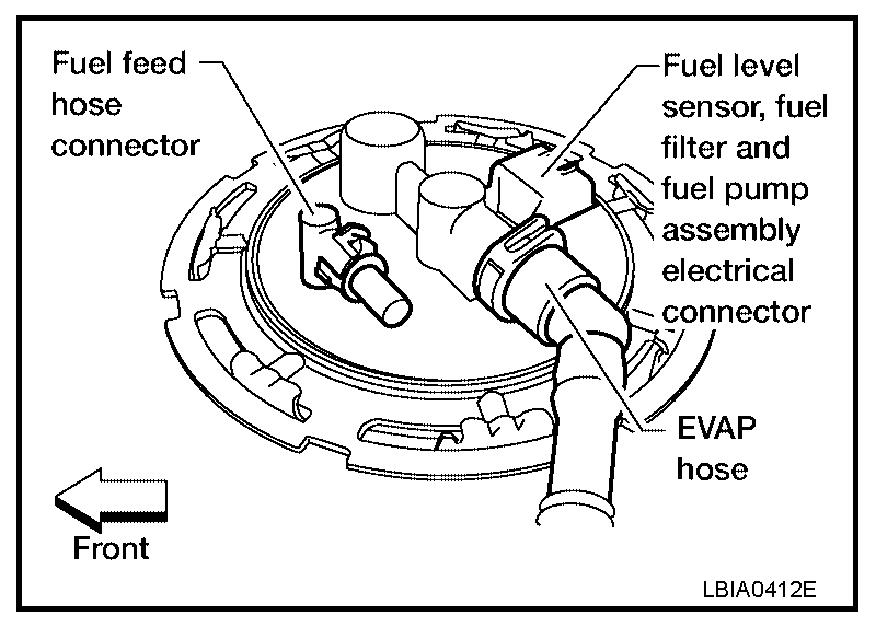
6. Disconnect the lower fuel filler hose from the fuel tank, the EVAP hose, and the vent pipe quick connector.
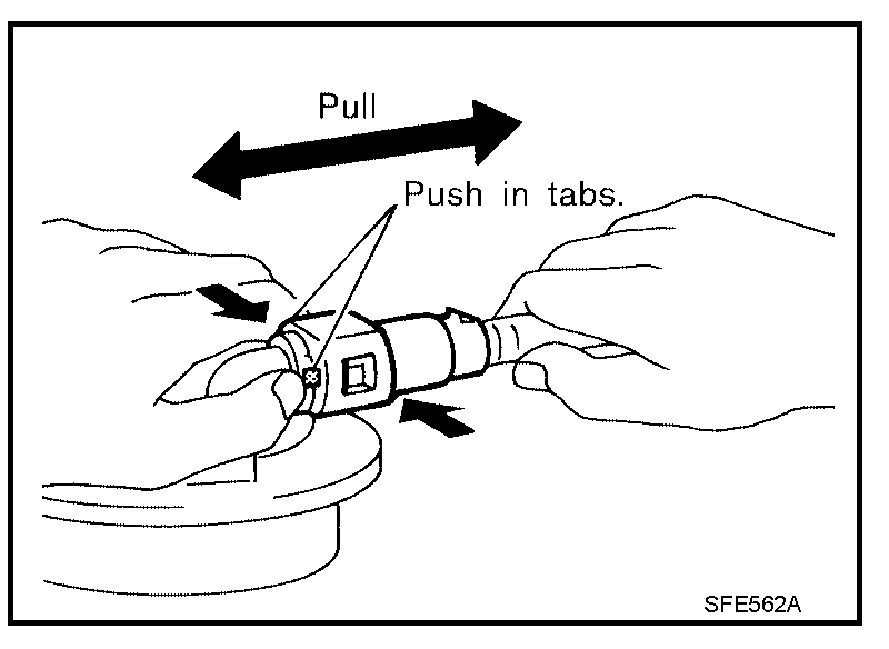
- Disconnect the fuel feed hose from the molded clip in the side of the fuel tank. Disconnect the quick connector as follows:
- Hold the sides of the connector, push in the tabs and pull out the tube.
- If the connector and the tube are stuck together, push and pull several times until they start to move. Then disconnect them by pulling.
CAUTION:
pic 3
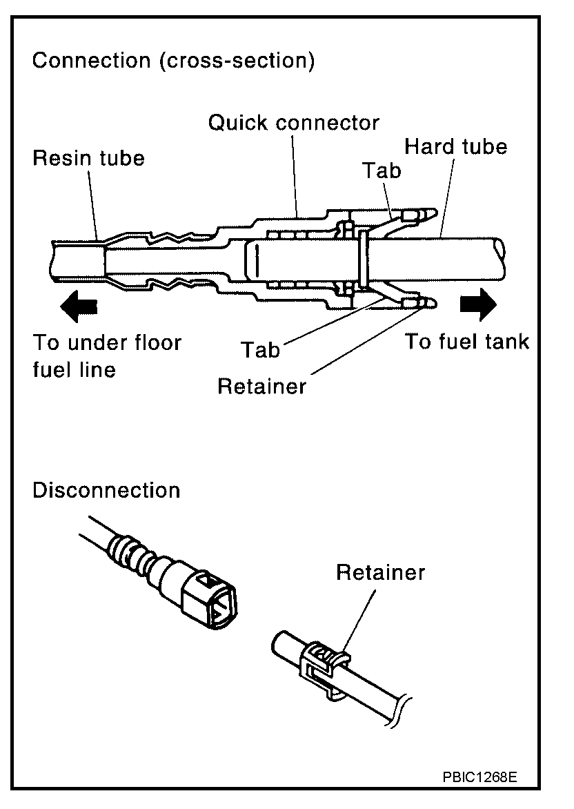
- The quick connector can be disconnected when the tabs are completely depressed.
- Do not twist the quick connector more than necessary. Do not use any tools to disconnect the quick connector.
- Keep the resin tube away from heat. Be especially careful when welding near the tube.
- Prevent any acid liquids such as battery electrolyte, from getting on the resin tube.
- Do not bend or twist the resin tube during connection.
- Do not remove the remaining retainer on the hard tube (or the equivalent) except when the resin tube or the retainer is replaced.
- When the resin tube or hard tube, or the equivalent, is replaced, also replace the retainer with a new one (semitransparent colored retainer).
pic 4
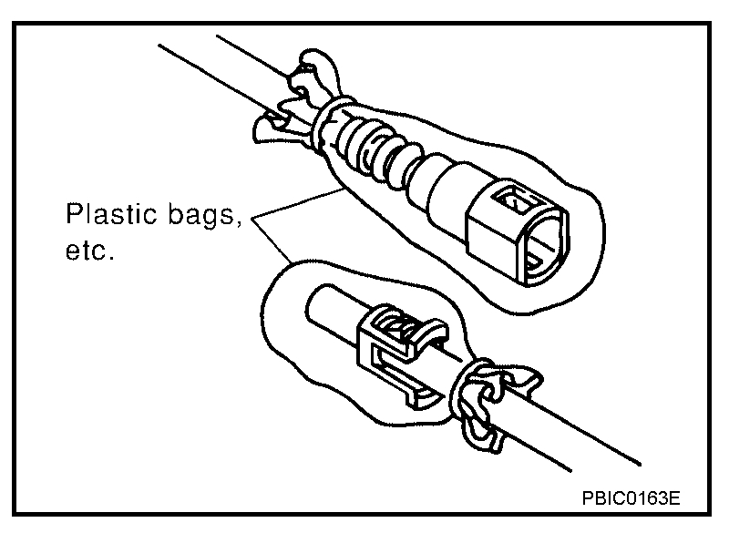
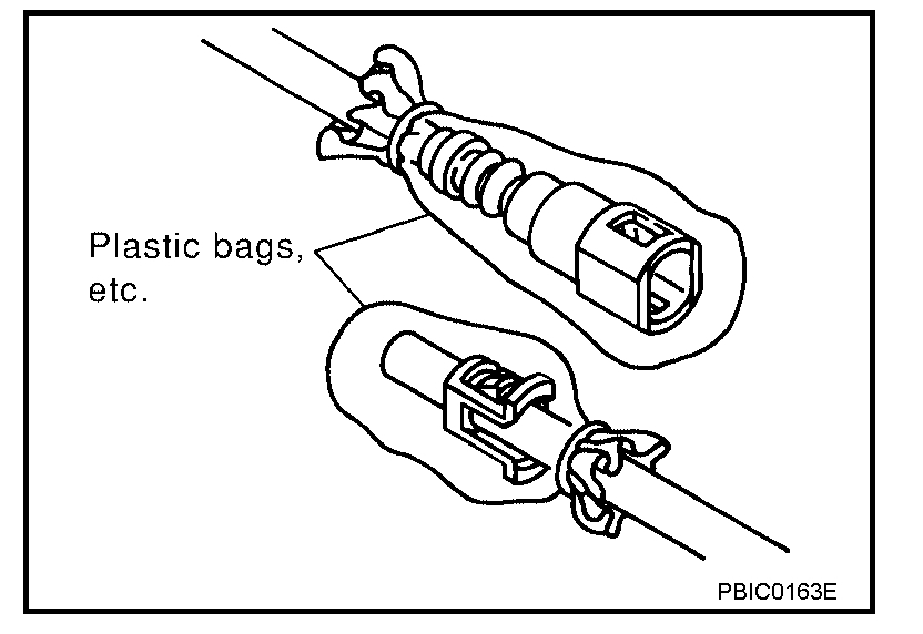
- To keep the quick connector clean and to avoid damage and contamination from foreign materials, cover the quick connector with plastic bags or suitable material as shown.
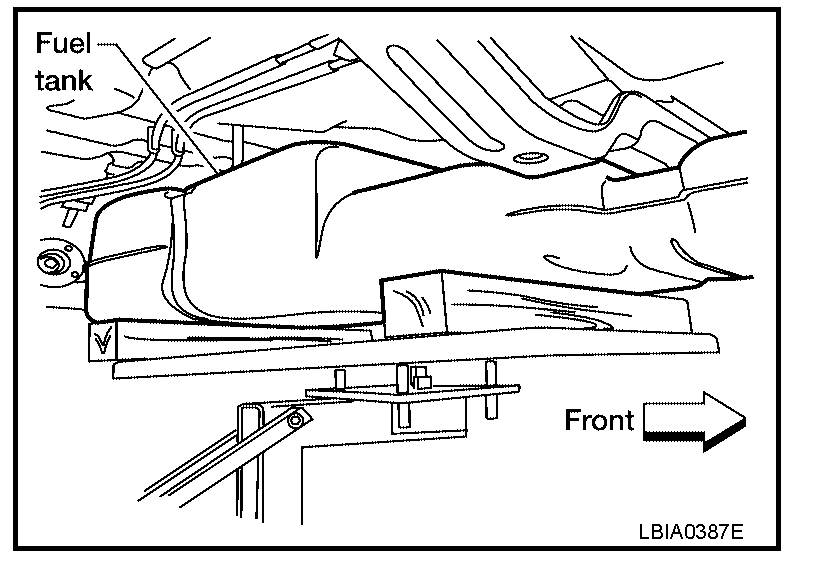
7. Remove the four bolts and remove the fuel tank shield.
8. Remove the propeller shaft. Refer to "REAR PROPELLER SHAFT".
pic 5
9. Support the fuel tank using a suitable lift jack.
10. Remove the three fuel tank strap bolts while supporting the fuel tank with a suitable lift jack.
11. Remove the fuel tank straps and slowly lower the fuel tank to access the top of the fuel level sensor, fuel filter and fuel pump assembly.
CAUTION: Do not lower the fuel tank too far to prevent damage to the fuel feed hose and the fuel level sensor, fuel filter and fuel pump assembly connector
pic 6
12. Disconnect the fuel level sensor, fuel filter, and fuel pump assembly electrical connector, and the fuel feed hose.
pic 7
Disconnect the quick connector as follows:
- Hold the sides of the connector, push in the tabs and pull out the tube.
- If the connector and the tube are stuck together, push and pull several times until they start to move. Then disconnect them by pulling.
CAUTION:
pic 8
- The quick connector can be disconnected when the tabs are completely depressed.
- Do not twist the quick connector more than necessary.
- Do not use any tools to disconnect the quick connector.
- Keep the resin tube away from heat. Be especially careful when welding near the tube.
- Prevent any acid liquids such as battery electrolyte, from getting on the resin tube.
- Do not bend or twist the resin tube during connection.
- Do not remove the remaining retainer on the hard tube (or the equivalent) except when the resin tube or the retainer is replaced.
- When the resin tube or hard tube, or the equivalent, is replaced, also replace the retainer with a new one (semitransparent colored retainer).
pic 9
- To keep the quick connector clean and to avoid damage and contamination from foreign materials, cover the quick connector with plastic bags or suitable material as shown.
13. Lower the fuel tank using a suitable lift jack and remove the fuel tank.
14. Disconnect the EVAP hose from the fuel pump and remove the EVAP hose from the molded clip in the top of the fuel tank.
pic 10
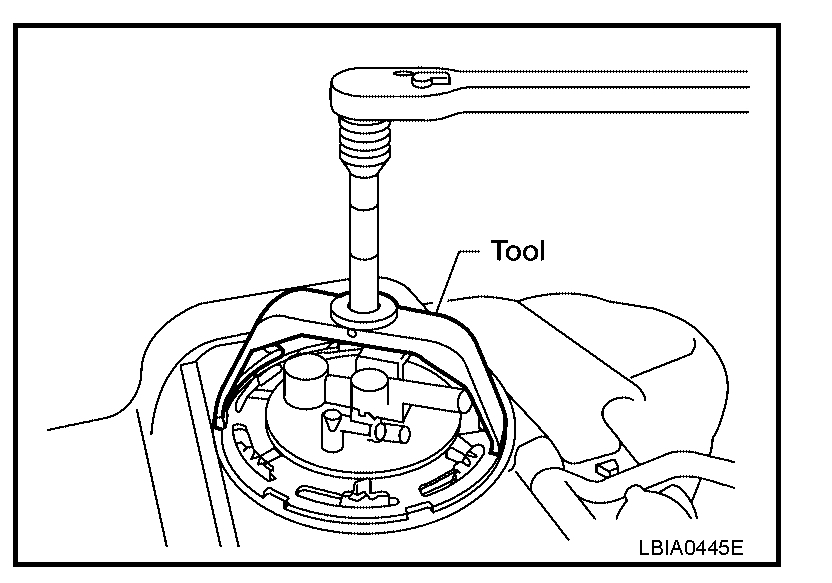
15. Remove the lock ring using Tool.
Tool number : - (J-45722)
16. Remove the fuel level sensor, fuel filter, and fuel pump assembly.
CAUTION:
- Do not bend the float arm during removal.
- Avoid impacts such as dropping when handling the components.
INSTALLATION
Installation is in the reverse order of removal.
- Connect the quick connector as follows:
- Check the connection for any damage or foreign materials.
- Align the connector with the pipe, then insert the connector straight into the pipe until a click is heard.
pic 11
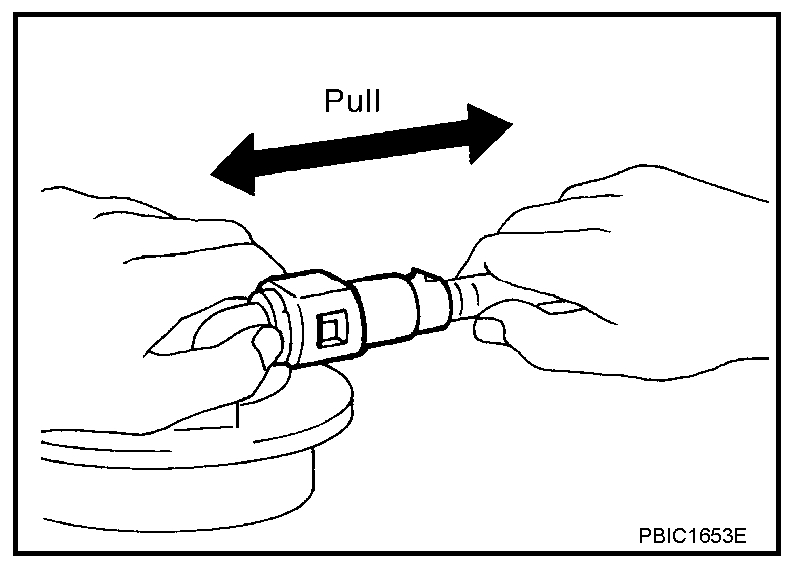
- After connecting the quick connector, make sure that the connection is secure by checking as follows:
- Pull the tube and the connector to make sure they are securely connected.
- Visually inspect the connector to make sure the two retainer tabs are securely connected.
CAUTION:
- Do not bend the float arm during installation.
- Avoid impacts such as dropping when handling the components.
INSPECTION AFTER INSTALLATION
1. Turn the ignition switch ON but do not start engine, then check the fuel pipe and hose connections for leaks while applying fuel pressure.
2. Start the engine and rev it above idle, then check that there are no fuel leaks at any of the fuel pipe and hose connections.
_________________________________________________________________________________________
Let me know if this helps or if you need anything additional.
Joe
Images (Click to enlarge)
Nov 30, 2019 at 10:16 PM