Here are he diagnostic procedures for the trouble code but you should be checking the basics first such as wire connections and grounding circuits.
DTC P1899: P/N SWITCH STUCK IN PARK OR IN GEAR
NOTE: Cruise control system is also referred to a Speed Control (S/C) system.
NOTE: Vehicles are equipped with a Transmission Range Sensor (TRS). TRS may also be referred to as Park/Neutral (P/N) switch or Park/Neutral Position (PNP) switch. If a component fails, PCM may use substitute value in its calculations to continue engine operation. In this condition, commonly known as limp-in mode, vehicle runs but driveability will not be optimum.
TRS circuit is monitored when transaxle is in Park, Neutral or Drive and vehicle is not in limp-in mode. DTC will set if PCM detects an incorrect TRS signal for given mode of operation.
Possible Causes
•Defective TRS
•Defective PCM
•Defective Connectors Or Wiring
Testing
1.Turn ignition off. Connect scan tool to DLC. Turn ignition on. Using scan tool, read DTCs. If GLOBAL GOOD TRIP is displayed and is equal to zero, go to next step. If GLOBAL GOOD TRIP is not displayed or is more than zero, go to step 6 .
2.Turn ignition on. Using scan tool, read P/N POSITION SWITCH state while moving gear selector through all positions. If scan tool does not display P/N and D/R in correct gear positions, go to next step. If scan tool displays P/N and D/R in correct gear positions, go to step 6 .
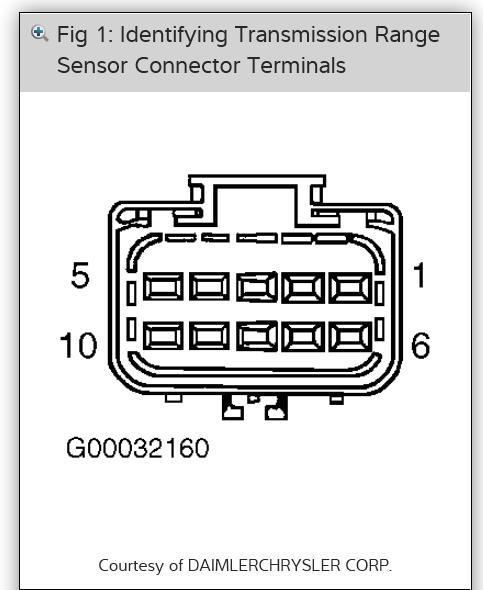
3.Turn ignition off. Disconnect PCM connectors. Disconnect TRS connector. Measure resistance between ground and TRS connector terminal No. 5, PNP switch sense circuit (Black/White wire at TRS; Brown Yellow wire at PCM). See Figure . If resistance is more than 100 ohms, leave connectors disconnected and go to next step. If resistance is 100 ohms or less, repair short to ground in Black/White wire and/or Brown/Yellow wire.
4.Measure resistance of PNP switch sense circuit (Black/White wire at TRS; Brown Yellow wire at PCM) between TRS connector terminal No. 5 and PCM connector C2 terminal No. 76. See Figure . If resistance is less than 5 ohms, leave PCM connectors disconnected and go to next step. If resistance is 5 ohms or more, repair open in Black/White wire and/or Brown/Yellow wire.
5.Measure resistance between ground and PCM connector C2 terminal No. 76, PNP switch sense circuit (Black/White wire at TRS; Brown Yellow wire at PCM). Move gear selector lever through all positions. If resistance switches from more than 10 ohms to less than 10 ohms, replace PCM. If resistance does not switch from more than 10 ohms to less than 10 ohms, replace TRS.
6.Conditions required to set DTC are not present at this time. Fault may be intermittent. Using scan tool, check freeze frame data to determine conditions when DTC set. Monitor scan tool while wiggling related wiring and connectors. Check related wiring and connectors for poor connections or damage to wiring harness. Repair any problems found as necessary. If no problems are found, test is complete.
Mar 16, 2014 at 1:09 AM