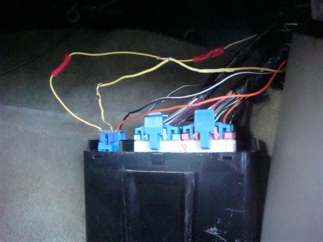
Anyone can help me and knows how to do bypass between:
1) The left yellow wire (in the DIM plug) (see pics)
2) To fuse 13 , ( C1 –Fuse box ,under passenger seat)
Image (Click to enlarge)
Jan 3, 2012 at 6:26 PM
FACTORYJACK
CAR REPAIR CONTRIBUTOR
4,159 POSTS
Cut the wire at each connector end, install a piece of wire in between.
Jan 3, 2012 at 7:08 PM
Advertisement
EFFI LAHAV
MEMBER
37 POSTS
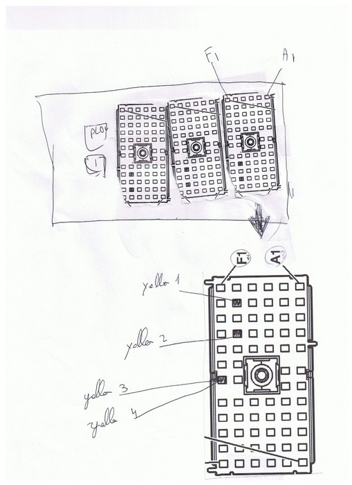
Can you please point exactly were do i need to connect. One point is the DIM ,that’s o.k. The other point is not clear to me. Can you please point it for me on the diagram? (The attachment)
Thanks
Image (Click to enlarge)
Jan 3, 2012 at 8:14 PM
FACTORYJACK
CAR REPAIR CONTRIBUTOR
4,159 POSTS
If the wire to the DIM is the one that is shorted, then it should be terminal B4, and there should only be one yellow wire in that cavity.
Jan 3, 2012 at 9:08 PM
EFFI LAHAV
MEMBER
37 POSTS
Yes ,in B4 there is only one yellow terminal.
Is that’s how I need to do the bypass?
Image (Click to enlarge)
Jan 3, 2012 at 9:37 PM
FACTORYJACK
CAR REPAIR CONTRIBUTOR
4,159 POSTS
Cut the wire at b4, connect and run an auxiliary wire to the dim terminal. If your fuse no longer blows, which should be the case if your diagnosis was correct, then you have bypassed your shorted wire.
Jan 3, 2012 at 10:47 PM
EFFI LAHAV
MEMBER
37 POSTS
I Cut the wire at b4, and connect it (with a auxiliary wire) to the dim terminal , passenger side front) .
the fuse did not burn, but I also still didn’t have the backlight in the switches on the IE. ?? What can be wrong?
Jan 5, 2012 at 5:16 AM
FACTORYJACK
CAR REPAIR CONTRIBUTOR
4,159 POSTS
What are the switches on the IE?
Jan 5, 2012 at 4:09 PM
EFFI LAHAV
MEMBER
37 POSTS
Sorry, it’s the switches for all the A/C unit , the Radio ,and the 3 switches bout side IE: the info,on /off ,dsdl,and reset.
Jan 5, 2012 at 4:51 PM
FACTORYJACK
CAR REPAIR CONTRIBUTOR
4,159 POSTS
Have you perhaps got the wrong wire at the DIM? It should be a yellow wire pin H, at the 10 pin blue connector C1. There aare two yellow wires in that connector, one is pin H in the middle, and one is pin K, on an end. H is the circuit you are after.
Jan 5, 2012 at 5:26 PM
EFFI LAHAV
MEMBER
37 POSTS
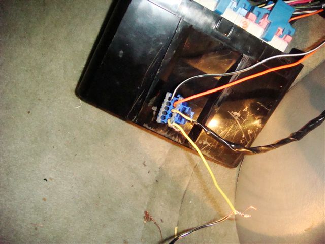
I may get it wrong, So I attached a pics to C1 and the yellow wires. I did cut in yellow #2 and did the bypass.
Can you please look if that’s the right one?
Image (Click to enlarge)
Jan 5, 2012 at 10:15 PM
FACTORYJACK
CAR REPAIR CONTRIBUTOR
4,159 POSTS
C1 @ the DIM, not the fuse block.
Jan 5, 2012 at 11:08 PM
EFFI LAHAV
MEMBER
37 POSTS
Yes I did the bypass between The DIM (pin 10 blue connector that’s connect to the DIM left side ((one of 3 plugs)) And the fuse box yellow wire #2 as in the pics.
Is that not right?
Jan 5, 2012 at 11:51 PM
FACTORYJACK
CAR REPAIR CONTRIBUTOR
4,159 POSTS
If you did pin 10 at the DIM, that is incorrect. The pins are actually letter designated, and you did pin K. The other yellow should be in the middle of that connector, pin H. Or if it were a number, pin 8.
Jan 6, 2012 at 12:23 AM
EFFI LAHAV
MEMBER
37 POSTS
maybe its not pin 10 ,but its the yellow wire on the left of the plug (see in the pics) Does the yellow wire in the middle is the one that i need to bypass?
Image (Click to enlarge)
Jan 6, 2012 at 1:09 AM
FACTORYJACK
CAR REPAIR CONTRIBUTOR
4,159 POSTS
Yes, the one in the middle.
Jan 6, 2012 at 1:46 AM
EFFI LAHAV
MEMBER
37 POSTS
Thank. And the other side is the “Yellow #2” in the fuse block (as in the schematic above) ?
Jan 6, 2012 at 2:00 AM
FACTORYJACK
CAR REPAIR CONTRIBUTOR
4,159 POSTS
In the picture I attached, at the far left, is the circuit you are describing. It is only showing one yellow wire at fuse block terminal B4, that goes to DIM terminal H. That is the circuit you run a separate wire on. You should gain the switch backlighting back, and if you did your diagnosis correctly, it will not blow the fuse.
Image (Click to enlarge)
Jan 6, 2012 at 3:54 AM
EFFI LAHAV
MEMBER
37 POSTS
I think… I understand….. And to make sure before I will make another mistake…..
Pin H (in DIM plug) should be connect to pin B4 in the fuse box.?
Pin C in (DIM plug) (Middle of blue plug in DIM plug) should be connect to pin A7 (or A8) in the fuse box ?
And I can bypass the 2 yellow wires to avoid any short?
Jan 6, 2012 at 5:41 AM
FACTORYJACK
CAR REPAIR CONTRIBUTOR
4,159 POSTS
Pin C has nothing to do with it. Pin H simply goes to B4 at the fuse block.
Jan 6, 2012 at 3:36 PM
EFFI LAHAV
MEMBER
37 POSTS
i connect pin H (DIM Plug) with B4 fuse box. No fuse was burn But i also did not have the backgrond light. ???
P.S. There is A power on H.
Jan 7, 2012 at 12:54 AM
FACTORYJACK
CAR REPAIR CONTRIBUTOR
4,159 POSTS
Did you restore the other circuit that was cut?
Jan 7, 2012 at 3:12 AM
EFFI LAHAV
MEMBER
37 POSTS
i dont have any circuit cul All are connected.
i did confirm that i connect pin H with B4 fuse box.
all fuses are o.k but i dont have the backgrond light. ???
i checked again and when i start the light ,The DIM gets 12v (from thye fuse box.
Jan 8, 2012 at 12:28 AM
EFFI LAHAV
MEMBER
37 POSTS
Any idie where cxab=n i look more? Maybe the DIM?V
Repair Safety Notice: This information is for general instructional purposes only. Vehicle repair can be dangerous. Verify all information, follow manufacturer service procedures, use proper tools and safety equipment, and consult a qualified repair shop when needed.