CAMSHAFT TIMING
CAUTION:Camshafts must be re-timed when either camshaft is disturbed. To avoid any mechanical failures, timing procedure must be performed as stated.
NOTE:
Procedures in Step 1) may already have been completed if sent here from a another procedure.
1. Remove valve covers. See VALVE COVERS. Remove lower intake manifold. Remove fuel supply manifold. Remove accessory drive belt. Remove thermostat housing. Remove camshaft roller followers.
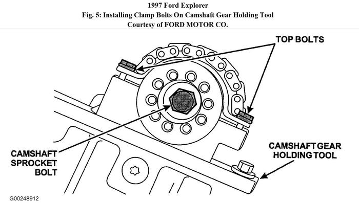
2. While observing timing mark on damper, turn crankshaft clockwise to position number one cylinder at TDC and install Crankshaft Holding Tool (T97T-6303-A) to hold crankshaft in position. This will prepare the engine for cam timing. See Fig. 34. Install Camshaft Gear Holding Tool (T97T-6256-B) and Adapter (T97T-6256-A) onto right camshaft sprocket and tighten top 2 clamp bolts of Camshaft Gear Holding Tool (T97T-6256-B) to 89 INCH lbs. (10 N.M). See Fig. 36.
CAUTION:
Right camshaft sprocket bolt is a LEFT-HAND threaded bolt.
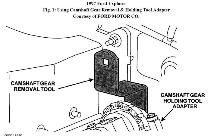
3. Using Camshaft Gear Removal Tool (T97T-6256-F), loosen right camshaft sprocket bolt. Loosen top bolts of Camshaft Gear Holding Tool (T97T-6256-B). See Fig. 1.
NOTE:
Camshaft timing slots are off-center.
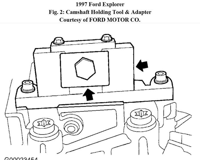
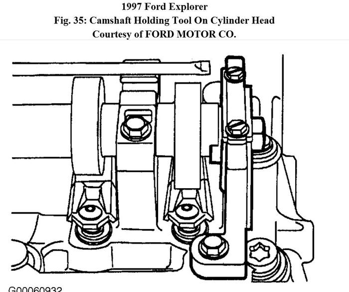
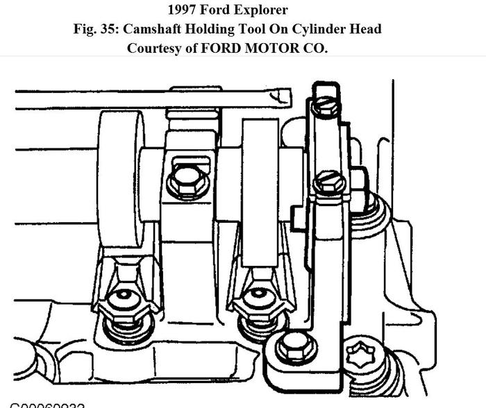
4. Position the camshaft timing slots below centerline of camshaft to allow proper installation of Camshaft Holding Tool (T97T-6256-C) and Adapter (T97T-6256-0) onto the cylinder head. Then, install both tools onto cylinder head. See Fig. 2.
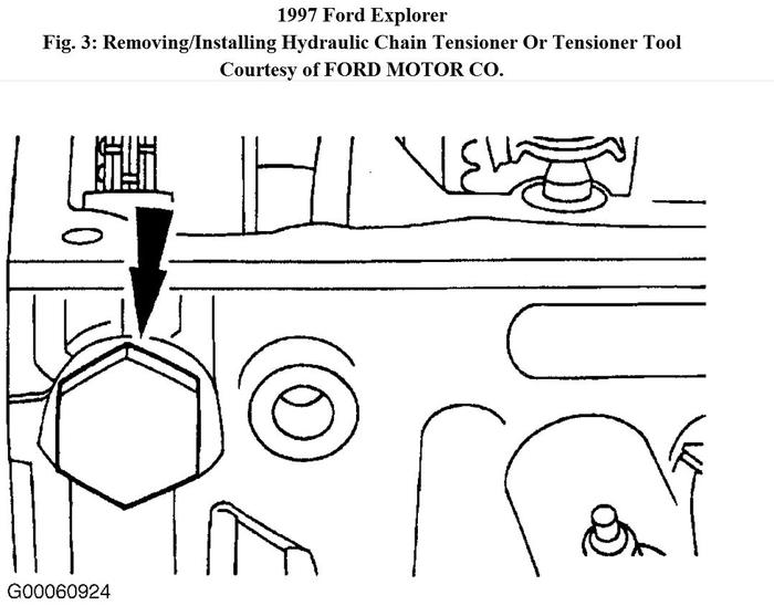
5. Raise and support vehicle. Remove right wheel and tire. Remove lower splash shield. Remove right camshaft tensioner and install Timing Chain Tensioner Tool (T97T-6K254-A). See Fig. 3. Remove vehicle supports and lower vehicle.
CAUTION:
Right camshaft sprocket bolt is a LEFT-HAND threaded bolt.
NOTE:
If Camshaft Gear Removal Tool (T97T-6256-F) is being used with torque wrench, keep torque wrench IN-LINE with tool and tighten camshaft sprocket to 45 ft. Lbs. (61 N.M). This tool will amplify the torque. Otherwise, tighten camshaft sprocket to 63 ft. Lbs. (85 N.M).
6. Tighten top 2 clamp bolts on Camshaft Gear Holding Tool (T97T-6256-B) to 89 INCH lbs. (10 N.M). Then, tighten camshaft sprocket bolt to 63 ft. Lbs. (85 N.M). See Fig. 1.
7. Raise and support the vehicle. Remove Timing Chain Tensioner Tool (T97T-6K254-A) and install right camshaft tensioner with a NEW washer. Tighten to 32 ft. Lbs. (44 N.M). Install lower splash shield, wheel and tire and tighten lug nuts to 100 ft. Lbs. (135 N.M) in a star pattern. Remove vehicle supports and lower vehicle. Remove all special tools from the cylinder head.
NOTE:
Leave top 2 clamp bolts loose on Camshaft Gear Holding Tool (T97T-6256-B).
8. Install Camshaft Gear Holding Tool (T97T-6256-B) and Adapter (T97T-6256-A) onto left camshaft sprocket. See Fig. 36.
CAUTION:
It is important that tool be installed correctly. If not, engine may run badly, with one cam being off by 180 degrees.
NOTE:
Camshaft timing slots are off center.
9. Position camshaft timing slots below centerline of camshaft to allow proper installation of Camshaft Holding Tool (T97T-6256-C) and Adapter (T97T-6256-D) onto rear of left cylinder head. Then, install both tools onto cylinder head. See Fig. 2.
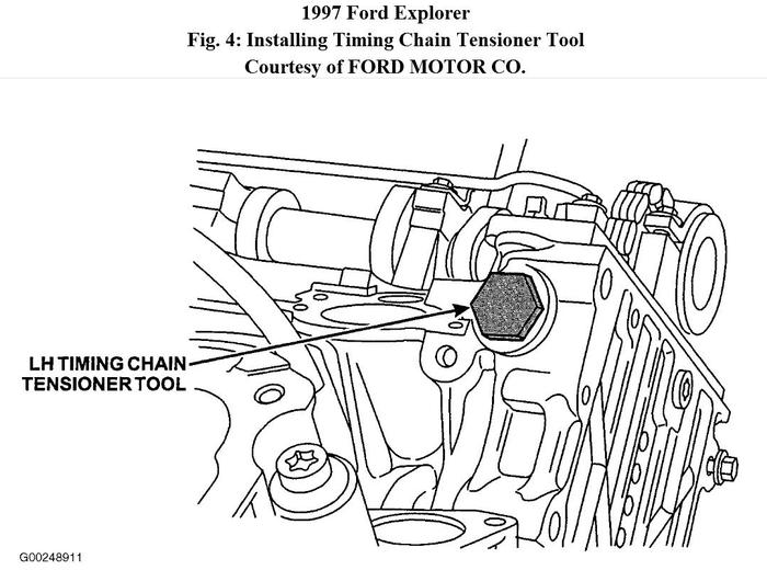
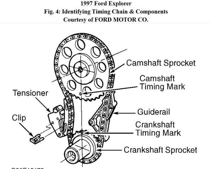
10. Remove left camshaft tensioner and install Timing Chain Tensioner Tool (T97T-6K254-A). See Fig. 4. Tighten top 2 clamp bolts on Camshaft Gear Holding Tool (T97T-6256-B) to 89 INCH lbs. (10 N.M). Then, tighten camshaft sprocket bolt to 63 ft. Lbs. (85 N.M). See
Fig. 5.
11. Remove Timing Chain Tensioner Tool (T97T-6K254-A) and install left camshaft tensioner with a NEW washer and tighten to 32 ft. Lbs. (44 N.M). Remove all special tools from cylinder head. Remove Crankshaft Holding Tool (T97T-6303-A) from crankshaft. Install accessory bracket. Tighten 4 bolts to 31 ft. Lbs. (42 N.M).
NOTE:
If camshaft cassettes were replaced, install accessory bracket at this time and tighten nut to specification.
12. Install radiator. Install the engine coolant temperature sensor and tighten to 11 ft. Lbs. (15 N.M). Connect engine coolant temperature connector. Install camshaft roller followers. See CAMSHAFT ROLLER FOLLOWERS. To complete installation, reverse removal procedure.
Images (Click to make bigger)
Wednesday, October 24th, 2012 AT 2:03 PM
