Will not idle/stalls

Tiny
ONEPHAT66
  • MEMBER
  • 1996 DODGE STRATUS
  • 2.4L
  • 4 CYL
  • 2WD
  • AUTOMATIC
  • 160,000 MILES
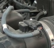
My car continues to shut off when idling, or at least idles terribly. I have replaced plugs, wires, IAC, EGR valve, upstream O2 sensor, cleaned throttle body, flushed injectors and replaced injector, o-rings, checked for vacuum leaks, etc. No matter what I do I cannot get this car to idle. I feel certain the base idle screw has been messed with previously due to the tamper plug was removed when I bought the car. I would like to start with checking/adjusting the base idle, but cannot find any adjustment procedures anywhere, (yes I know, you are not suppose to adjust these screws, but someone has already). Then, assuming it does not fix the problem I need to know where to go next.
Thursday, December 6th, 2018 AT 10:06 AM

26 Replies

Tiny
CARADIODOC
  • MECHANIC
  • 33,742 POSTS
There is no idle speed adjustment screw. Idle speed is computer-controlled. If the engine will only start if you hold the accelerator pedal down 1/4", and/or it tends to stall at stop signs, but it runs smoothly and normally at other times, chances are the battery was recently disconnected or run dead, and the Engine Computer has not relearned "minimum throttle" yet. It must see a very specific set of conditions to do that. If you have a rough idle due to misfires, that is a different issue. If you have a rough idle because idle speed is too low, before you waste time and money on anything else, go out and drive the car at highway speed with the engine warmed up, then coast for at least seven seconds without touching the pedals. At the end of that seven seconds, the computer will take the reading from the throttle position sensor and put that in memory. From then on, any time it sees that same voltage, it will know your foot is off the accelerator pedal and it must be in control of idle speed.

That procedure solves low idle speed on Chrysler products ninety nine percent of the time. If it does not work on your car, you will need a scanner to view live data so we can see the "idle steps" the computer has placed the automatic idle speed motor at.
Was this
answer
helpful?
Yes
No
-2
Thursday, December 6th, 2018 AT 4:26 PM
Tiny
ONEPHAT66
  • MEMBER
  • 20 POSTS
Caradiodoc, you are incorrect regarding the idle adjustment screw. Re-read my post clearly regarding this screw. This problem is not due to someone disconnecting the battery, or a dead battery. I am the only person who has worked on it since I have owned it over two years. I do not have to step on the pedal at all to start it, even when it shuts off. I have no problem ever starting it, it just will not stay running unless it is above idle (1000+RPMs). I am pretty certain your seven second trick is not going to work, but I will humor the idea and try it.
Was this
answer
helpful?
Yes
No
Thursday, December 6th, 2018 AT 5:18 PM
Tiny
CARADIODOC
  • MECHANIC
  • 33,742 POSTS
You will need to post of photo of what you think the idle screw is. I will show that to the engineers who designed the system, the people who built the throttle body, and the Chrysler instructor who who taught the classes where I learned about this system. This will come as quite a surprise to them.

Idle speed is adjusted with the automatic idle speed motor, (AIS motor). Some manufacturers call it an "idle air control", (IAC), motor, but it is the same part. That is a "stepper" motor that is controlled by the Engine Computer. It does not have brushes like you would normally associate with a regular motor. It has four electromagnetic coils that are pulsed with varying voltages and polarities to place the armature in the desired orientation. On newer vehicles, instrument cluster gauges also are stepper motors with pointers attached to them.

As the armature rotates, it is part of a threaded shaft that gets run in and out to extend or retract the pintle valve on the end of it. As it retracts that valve, it opens up the air passage that bypasses the throttle valve. While this lets more air in, the computer increases the number of milliseconds the injectors are pulsed open to increase the amount of fuel to go with that extra air. Even if there was an idle speed screw, that would only give you more air, not more fuel to go with it.

We had a common problem in the late 1980's and early 1990's with stalling from low idle speed on the 3.0L engines. That was caused by the air passage becoming plugged with carbon. Those passages could be cleaned after just removing the AIS motor. Since then, additives in all gas has become much better, so we have not seen this for a real long time.

The scanner I mentioned will show you the number of idle "steps" the computer has placed the AIS motor to, from "0" to "256". For a properly-running engine, step 32 is typical. With a single-cylinder misfire on a V-6 engine, you will find it closer to step 50. As a demonstration, a Jeep instructor disabled six injectors on a running V-8 engine, and it was able to maintain idle speed on just the last two cylinders. Obviously it did not run well, but it showed how much control the computer has over idle speed. The clue here for your engine is if you find it on step "0", minimum throttle has not been learned, and the computer is not trying to control idle speed. If you find it is requesting a specific step number, we have to look at what you are seeing for a response. If the number is fairly high but idle speed is too low, there is a running problem that must be diagnosed. The computer is trying to raise idle speed, but without success. If the number is low, but higher than "0", and idle speed is also too low, we have to look at the other sensor readings to figure out why it wants idle speed to be that low.

I have a Chrysler DRB3 for all of my vehicles. That scanner also allows you to run idle speed up to 2,000 rpm, in 200 rpm increments, to test the operation of the AIS motor and its wiring. On some models that will not work until minimum throttle has been relearned. You will get a message about "test not allowed", but you have to know why it is doing that. The point of interest here is if it shows it is in fact requesting the higher speed but not actually getting the desired response, there will be a diagnostic fault code in the Engine Computer if the cause is related to an electrical issue it can detect. If idle speed does not increase and there is no fault code, you have to look at things it cannot monitor, such as that carbon plugging the passage.

As for disconnecting the battery, I never said you did that, and you know I have no way of knowing no one else worked on your car. I always try to provide as much information as possible because a lot of other people will read this in the future when researching a similar problem. I include all the hints and clues I can think of knowing full well they will not all apply to your car. Nine out of ten times when I mention the battery, someone will come back and include that it had been done, but they did not think it was worth mentioning. I would be doing you a disservice if I did not mention it, especially since this is such a common problem. With all the work you did already, there is also a good chance you unplugged the Engine Computer. That also removes memory power and erases everything in its memory. All other sensor and operating data will be relearned right away when you resume driving, except for minimum throttle. The computer needs to see high manifold vacuum when the car is moving, and the throttle position sensor's signal voltage remains rock solid for seven seconds. You can get high vacuum by snapping the throttle, but not for seven seconds. That is why you must be driving and coasting. If the computer sees the TPS's signal voltage change within that seven seconds, it knows you have your foot on the accelerator pedal, so it stays out of your way and lets you be in control of idle speed. By the high vacuum for prolonged period of time, it knows the car is moving, it knows the throttle is closed, and it knows TPS voltage is solid and steady. That is when it memorizes that signal voltage. From then on, whenever it sees that same voltage, it knows it must be in control of idle speed.

Every once in a while we will run into one where this procedure does not work the first time. That can usually be attributed to the brake light switch being out-of-adjustment. Vibration from bumps in the road can make it appear you're pressing the brake pedal. That cancels the minimum throttle relearn. The clue to that is it will usually work if you hold the brake pedal up with your foot while coasting. Professional mechanics usually perform a test-drive to do this relearn so their customers do not come back with a complaint of stalling. They are usually the people who run into this problem with the brake light switch. Car owners are more likely to complain about the engine speeding up 200 rpm intermittently at highway speed, or they mistake it for the transmission slipping intermittently. This is all due to the torque converter lock-up clutch disengaging due to that brake light switch. That switch has multiple switches built in, and the one that tells the Engine Computer to request the lock-up clutch to disengage is same circuit that inhibits minimum throttle relearn. That circuit is independent of the brake light circuit and cruise control.

It is important to remember that everything I have shared pertains to a properly-running engine that is stalling at idle. If you have rough running or misfires, the EGR valve is the only thing you listed that could be involved, but you have that covered. Have you read the diagnostic fault codes? I can explain how to do that yourself if you want me to. You can go here:

https://www.2carpros.com/trouble_codes/obd2/p0200

To see the definitions, or I can interpret them for you. Also let me know if you have the single or dual-cam engine. There is a very elusive problem related to camshaft timing, but it only affects the single-cam engine.
Was this
answer
helpful?
Yes
No
+1
Thursday, December 6th, 2018 AT 6:39 PM
Tiny
ONEPHAT66
  • MEMBER
  • 20 POSTS
The idle screw I am referencing is to set base idle. It had a tamper cap over it at one time and is adjusted with a small allen wrench. Engine is a dual cam 2.4. I have no diagnostic codes what so ever. I am not a certified mechanic, but not a shade tree either. I am a recently retired Navy jet mechanic, and although cars and jets are quite different, I know my way around cars very well. I do almost all my own work, this just has me stumped because I do not have all the fancy diagnostic equipment and working on vehicles is not my primary job. Tomorrow I will try the seven second trick as well as reading the idle steps. Does the information you mentioned above apply to this engine? Tomorrow I should have data and an update. The car has had 1000's of miles put on it since the battery was disconnected. I know Dodge's are bad about idle issues with a less then perfect battery voltage, but mine has good voltage (do not remember exact voltage but will check tomorrow). Sorry about the harsh response earlier, just did not want you to think I barely know how to change oil, because it could not be further from the truth. I am just frustrated with this issue and even had (the best Dodge mechanic in town) look at it twice with no luck.
Was this
answer
helpful?
Yes
No
Thursday, December 6th, 2018 AT 7:49 PM
Tiny
ONEPHAT66
  • MEMBER
  • 20 POSTS
Okay, I checked my scanner and it does not monitor the idle steps unfortunately. I tried the seven second trick and was excited at first, but when I pulled into the driveway I could not keep it running. I double checked transmission fluid level to make sure transmission pressure was not the issue (at least caused by low fluid), and checked the battery voltage again, had 12.2 volts key off, 14.3 volts running. I am stumped.
Was this
answer
helpful?
Yes
No
Friday, December 7th, 2018 AT 4:12 PM
Tiny
CARADIODOC
  • MECHANIC
  • 33,742 POSTS
Dandy. Voltage isn't the issue for running problems. What can happen is one of the six diodes inside the alternator fails, then the most current you can get is exactly one third of the unit's maximum current rating. Most vehicles can still run on that, but since one of the three phases is missing, "ripple" voltage goes very high. That is what causes the trouble. GM has had a real big problem with that since their generators were redesigned for the '87 model year. Those develop huge voltage spikes that can take out a diode, the internal voltage regulator, and those spikes can be magnetically induced into adjacent wires where they interfere with computer sensor signals.

These voltage regulators are of the "switch-mode" design that turns current through the field winding on and off very quickly, just like is done in an ignition coil. We want those spikes to fire spark plugs, but they are harmful to computer circuits. As long as I'm on this topic, the battery is the key component in damping and absorbing those spikes, but as they age and the lead flakes off the plates, they lose their ability to do that. To reduce the very high number of repeat generator failures on GM vehicles, when you do have to replace one, always replace the battery at the same time unless it is less than about two years old.

This same duty-cycle switching system has been used by Chrysler, Ford, and the imports starting with Chrysler's first electronic regulator in 1970. GM had, in my opinion, the world's second-best generator starting in 1972 with its built-in regulator, but all of these used the same duty-cycle switching principle, and not one of them ever had this huge problem with voltage spikes that the '87 and newer GM units do. This is something new, so a lot of older mechanics aren't aware of it or don't believe it.

Basically, perform a charging system test with a professional load tester. If you can get close to the maximum current the generator, ("alternator" is strictly a Chrysler term), is rated at, all the diodes are okay. If you can only get one third of that maximum, you'll find ripple voltage is very high. Most testers just show that on a relative bar chart, but a few models do print it out as a value.

To get back to the idle issue, I can't stress enough that whatever screw you found is not meant for setting idle speed. There are two times that would be the case. The first is on carburetors. There, when you use it to open the throttle blade a little more, you get more air flow, and it's that air flow that draws in more fuel. That screw is only doing the same thing you could do with your foot.

There used to be some import engines back in the '80s and maybe even in the '90s that did indeed have an idle speed screw, but there was a big procedure involved in setting those. Opening up the throttle blade a little more increased air flow, and that volume of air was measured by the mass air flow sensor. That is the major contributor to fuel metering calculations. Based on its readings, intake air temperature readings, and coolant temperature readings, the computer calculated how long to hold the injectors open to get the desired amount of fuel to go with that air. Most of those systems had throttle position sensors that were adjustable, and you had to set them to read a specific voltage at idle. Since a number of factors interacted, it could be a very tedious procedure to set the screw and the TPS to make the engine run right. Stumbling on acceleration was a common symptom. To complicate it even more, there was often a fourth wire going to a switch inside the TPS that only turned on at idle. That was one more variable that complicated the system. I remember listening to a coworker whine and snivel that the engine would run well but idle speed was too high, or it would surge with idle speed too low, depending on how he adjusted the TPS to make that switch turn on or off at the wrong times.

Chrysler's system is different, going all the way back to '83 models. Their computers learn the voltage coming from the TPS at idle, so there is no adjustment needed or provided. Once minimum throttle has been learned, if you were to install a replacement sensor that develops a slightly lower voltage at idle, the computer will immediately see that as soon as you turn on the ignition switch, and it will immediately put that in memory as the new minimum throttle voltage. It knows that value didn't change on its own. The sensor has to be different, so it accepts the new voltage. If you were to put the old sensor back in, or a new one that develops a slightly higher voltage at idle, the computer will assume you have your foot on the accelerator pedal, and it will not try to control idle speed. That new value will be put in memory the next time you coast for seven seconds, which is about half of a typical off-ramp. It is common to read of people complaining of idle problems, and before we can reply, they post a follow-up claiming the problem "cleared up on its own".

The issue here with older fuel injected import engines is the screw only adjusted the amount of air entering the engine. Fuel delivery increased automatically in carburetors, but not so with throttle bodies. The next concern is Chrysler is the only manufacturer that never needed a mass air flow sensor to make their engines run right. That means that when you open the throttle blade, either with a screw or with your foot, the Engine Computer has no way of knowing the volume of air entering the engine. Instead of playing with a screw, you can accomplish the same thing by creating a small vacuum leak. That will raise engine speed, but without a corresponding increase in power. You need to increase fuel to go with that air. The computer controls idle speed by changing the amount of air and fuel at the same time. Air is increased by pulsing the AIS motor, and fuel is increased by lengthening the on-time of the injectors. Those two together get the mixture real close to perfect, then, once the coolant temperature reaches a magic temperature of around 160 degrees, the computer adds the front oxygen sensor readings to the fuel metering calculations as a fine-tuning adjustment. The amount of mixture correction can be read on the scanner too to see if the computer is adding or subtracting fuel from the pre-programmed values.

To not leave you with the mystery of the camshafts, idle quality can be affected by cam timing even though the engine seems to run fine otherwise. With the dual cam engine, if one sprocket is off by one tooth, idle quality suffers, the computer tries to bump up idle speed, then since the low speed was not due to load on the engine, speed goes too high, then the computer tries to correct that again. Surging is the most common complaint. By the way, Chrysler's main sensor for fuel metering is the MAP sensor. It simply looks at manifold vacuum to determine load on the engine. If you have a vacuum leak, or you physically open the throttle blade, vacuum goes down simulating the engine is under load, the MAP voltage will go up a few hundredths of a volt, and the computer will see that as the need for more fuel. If that is bad enough, you might see black smoke out the tail pipe.

The real elusive problem with the single-cam engine is first the Check Engine light turns on and the fault code is "cam and crank sync". That shows up if the timing belt jumps one tooth. If the belt jumps two teeth, the computer shuts the engine down to protect the valves. At three teeth off, valves will be hit by the pistons and will be bent. The real clinker is when the belt is off by one and a half teeth! That is right on the edge of where the engine gets shut down or is allowed to run, and can cause intermittent stalling. To add to the frustration, inspection will usually show the timing belt has not jumped a tooth.

The cause is the dowel pin between the camshaft and its sprocket has sheared off, and the camshaft has slowly rotated slightly retarded. The camshaft sensor is on the other end, on the driver's side of the engine, so it's seeing camshaft position, not sprocket position. By the time you get this one, a number of hands have been in there trying to figure this out, and most of them will have been in the ignition system because very often one ignition coil is still firing two spark plugs, but intermittently. Anyone who has solved one of these once before will observe the ASD relay is chattering on and off during cranking as an important clue. The computer is confused by the mismatched timing signals from the cam and crank sensors, so it doesn't know if it should turn the ASD relay on or off. Normally it gets turned on during engine rotation, (cranking or running), and that sends current to the ignition coils, injectors, alternator field, fuel pump or pump relay, and the oxygen sensor heaters. This dowel pin problem only applies to the single-cam engine. It's a pretty simple and fast repair, ... Once you know about it.
Was this
answer
helpful?
Yes
No
Friday, December 7th, 2018 AT 6:24 PM
Tiny
CARADIODOC
  • MECHANIC
  • 33,742 POSTS
I reread your comment about you couldn't keep the engine running. That is different than simple low idle speed. That is reminiscent of MAP sensor problems a long time ago. GM developed the MAP sensor that used a piezoelectric crystal, similar to a phonograph cartridge, and they had a huge failure rate with them, "so they sold them to Chrysler", as the story goes. Naturally, Chrysler had a big problem too. The secret, I found out, to keep the engine running was to keep moving the accelerator pedal. It didn't matter which way, how far, or how fast. As long as it was moving, the Engine Computer knew it couldn't rely on its readings, so it "injected" an approximate reading based on other sensor readings and operating conditions, to run on. It surprised a lot of owners when they had to have the vehicles towed to the shop, then we drove them in.

GM redesigned the sensor to use a "strain gauge", which is a long thin piece of wire wrapped around a core. When vacuum tugged on the diaphragm attached to the wire, it stretched it which changed its resistance. Circuitry amplifies that change to develop the signal voltage. All of those defective sensors were replaced by around '91 or '92, and since then their reliability has been very good. It is still possible you could have a failing sensor, but a better suspect would be a cracked or dry-rotted vacuum hose going to it. 1996 is right in the middle of when they changed from using a vacuum hose to using a sensor with a port that plugs right into the side of the throttle body. If you have that style, check for other vacuum leaks. If you have the hose yet, check that, and check if it has a dip in it where condensed gas fumes can collect and block the hose.

There are a number of different fault codes that can set related to the MAP sensor, but those that refer to signal voltages that goes outside the acceptable range only set if that voltage goes outside 0.5 to 4.5 volts. A change of just a few hundredths of a volt means a lot to the Engine Computer and engine performance. A vacuum leak can affect the sensor's readings and how the engine runs, but if those voltages stay within the acceptable range, no fault code will be set. This is where an engine performance specialist will look at the sensor's readings on a scanner to see if they seem right. This is one time where substituting a known good sensor might make sense, but typically when one of these starts to fail, it rarely takes more than a few days for them to fail completely, and set a fault code
Was this
answer
helpful?
Yes
No
Friday, December 7th, 2018 AT 6:46 PM
Tiny
ONEPHAT66
  • MEMBER
  • 20 POSTS
So check MAP sensor?
Was this
answer
helpful?
Yes
No
Saturday, December 8th, 2018 AT 8:43 AM
Tiny
ONEPHAT66
  • MEMBER
  • 20 POSTS
I will get that idle screw picture to you as well when I get a chance. Most of those vehicles have a screw to set "base" idle, then computer does the rest. I get what you are saying, but these cars do indeed have an idle screw. I have also heard of Chrysler vehicles having issues idle issues due to poor battery voltage, so that is why I wanted to rule that out. I guess I should have stated earlier that when the car shuts off at idle, sometimes it just shuts off, no warning. Sometimes though, it will hunt for an idle, but eventually shuts off. So I am guessing with everything you said last, check the MAP sensor?
Was this
answer
helpful?
Yes
No
Saturday, December 8th, 2018 AT 8:50 AM
Tiny
ONEPHAT66
  • MEMBER
  • 20 POSTS
I checked and do not have the sensor with the hose. It has a three wire connect that is somewhat round. I pulled the MAP sensor out and it is pretty grungy with carbon build up. Never got any engine codes though. Replace?
Was this
answer
helpful?
Yes
No
Saturday, December 8th, 2018 AT 12:56 PM
Tiny
CARADIODOC
  • MECHANIC
  • 33,742 POSTS
I did not describe the MAP sensor codes as well as I should have. For teaching theory, 0.5 to 4.5 volts is the magic values we use. The signal voltage must fall outside that range to trigger a fault code. In actual practice, you might it is closer to 0.38 and 4.72 volts, for example. The point is, if there is a defect inside the sensor's circuitry, or with the wiring, the voltage almost always goes all the way to 0.0 volts or 5.0 volts, so when a fault code is set, you aren't going to have to guess if the voltage shown on the scanner is good or bad. The exception is when you have an intermittent problem. Suppose there is a stretched terminal in the connector for the 5.0 volt feed wire, and it breaks its connection for an instant when you fly over a huge pot hole. The signal voltage will pop down to 0.0 volts, then go back to normal. You would see the normal voltage on the scanner, but the computer will have detected that momentary drop to 0.0 volts and it will have set the fault code, "MAP voltage too low". Intermittent problems like this, and permanent failures are just as likely to be caused by wiring problems as sensor problems, so when a part is referenced in a fault code, it is important to check the wiring and connector terminals first before ordering that part.

The concern we have next is you can get a wrong signal voltage from the MAP sensor, but if it is still within that acceptable range, no defect will be detected and no fault code will be set. This will not be due to a broken or grounded wire, but it could be caused by corrosion between two adjacent terminals in a connector or two mating terminals. More commonly that is caused by a vacuum leak, and once in a while by a sensor that is starting to fail.

Chrysler is the only manufacturer that uses only the MAP sensor for its main fuel calculations, and those signal voltages are very precise. While they don't actually do this, they could measure engine rpm with it by measuring the tiny pulses of increased vacuum each time a piston takes a gulp of air. The signal voltage will only change a few thousandths of a volt, but that has meaning to the computer. Given that they are that accurate and precise, it is easy to see how the readings can be adversely affected by a vacuum leak, or reduced vacuum from a jumped timing belt.

This brings us to another chapter when you find no fault codes, and you mentioned,

"sometimes it just dies, no warning. Sometimes though, it'll hunt for an idle, but eventually dies".

That description often applies to the crankshaft position sensor and the camshaft position sensor. In later models, starting around 2000 or 2001, once running, the engine could continue running if one of those sensors failed, but once stopped, you could not get it to restart because the computer wouldn't know which ignition coil and injector to fire first. In earlier years like yours, you must have signals from both sensors to tell the Engine Computer the engine is rotating. When it sees that during cranking, it turns on the automatic shutdown, (ASD) relay, which, as I mentioned earlier, sends current to the ignition coils, injectors, and fuel pump. If the signal drops out from either sensor, the computer turns the ASD relay off, and the engine stalls. The problem in diagnosing this is it takes some time for the computer to detect that missing signal and set a fault code. If you erase the fault codes, either with a scanner or by disconnecting the battery, those codes almost never set again just from cranking the engine. They set when a stalled engine is coasting to a stop. Even running at low speed might not give it enough time to detect the missing signal before the crankshaft stops rotating.

This is where you have to rely on a scanner. Mine lists the two sensors with a "Present" or "No" during cranking to show if their signals are showing up. If one shows "No", it could be wiring, connector terminal, or sensor-related. If it jumps rapidly back and forth between "Present" and "No", it is usually caused by the sensor. If both signals show a steady "Present", look at the "Cam and crank sync". I can't remember how that is shown, but it typically would be something like "Yes" or "No" or "In or "Out". If the indication is they are not in sync, the most common suspect is a jumped timing belt. That will cause hunting idle speed too.

The clues here are while idle speed is hunting up and down erratically, you will see the AIS motor step number remaining fairly steady, and ignition timing is varying wildly. That means idle speed is varying because spark timing is erratic, not because the computer is running the AIS motor back and forth.

Both of these sensors have high failure rates on almost all brands of cars, and it is real common for them to fail by becoming heat-sensitive. Often they work fine until a hot engine is stopped for a short time, as in when stopping for gas, then during "hot soak", engine heat migrates to the sensor, causing it to fail. They typically work again after cooling down for about an hour. Leading up to that failure, they can cut out intermittently while driving.

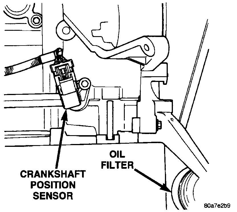
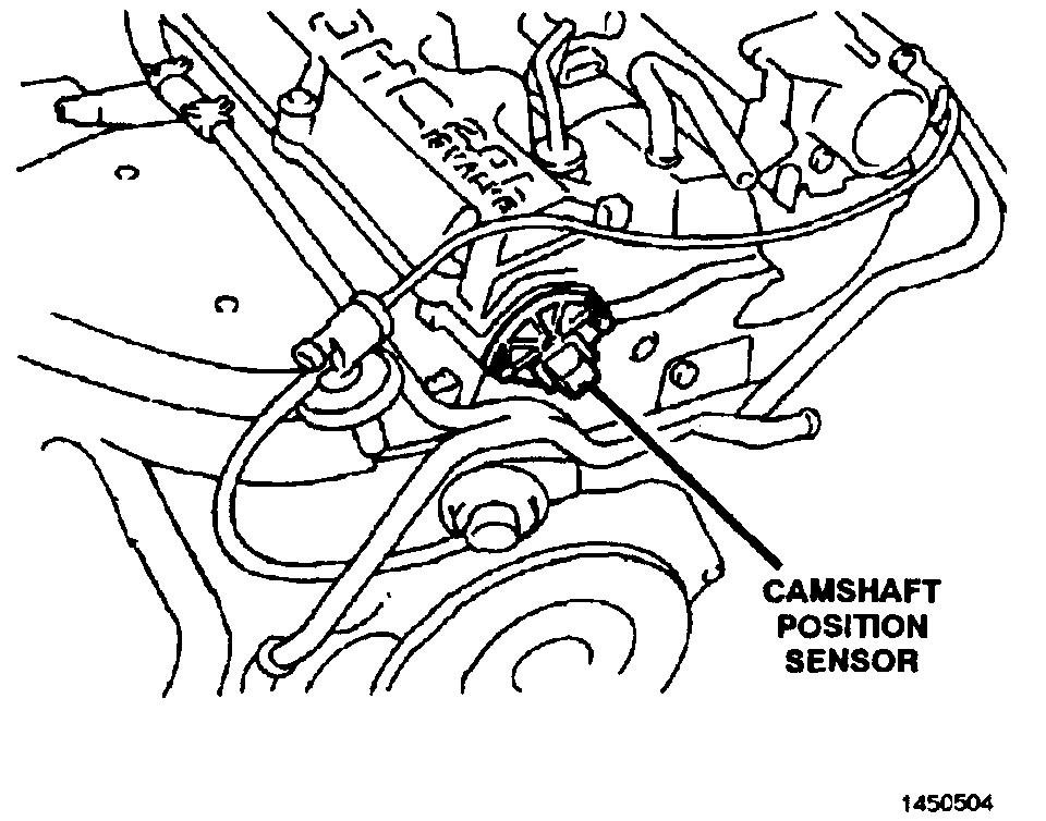
On V-8 engines that use a distributor, the crankshaft position sensor causes the most problems. On the 2.0L and 2.4L engines, the camshaft position sensor causes a lot more problems than the crank sensor. For a '96 model, if your cam sensor is still original, the new one will require you to replace the connector pig tail. They had a better version from a different application, so rather than create another part, they took what worked better and adapted it to your engine by replacing the connector to match that new sensor. If that connector has been replaced already, replacing the cam sensor is a two-minute job. It sits on the driver's side of the head. The crank sensor is on the back of the block, near the passenger side. It's easy to reach from underneath, but it's easier if the car is on a hoist so you can stand up.
Was this
answer
helpful?
Yes
No
Saturday, December 8th, 2018 AT 3:10 PM
Tiny
ONEPHAT66
  • MEMBER
  • 20 POSTS
Yeah, I know where the sensor is, and just had it out recently, (this idle issue was way before this), and even replaced the o-ring), and would have replaced it but had no codes and did not want to just throw money at it. So you are doing a lot of explaining, but I do not have the fancy equipment or perimeters to gauge my findings against. Just the basics will work. I am guessing you are suggesting I replace the cam sensor? MAP sensor is getting replaced cause it was nasty dirty, I will replace cam sensor if needed, just need good cause since I am not getting a code for it. I am guessing it is original.
Was this
answer
helpful?
Yes
No
Sunday, December 9th, 2018 AT 11:48 AM
Tiny
CARADIODOC
  • MECHANIC
  • 33,742 POSTS
You' are seriously limited in what you can do without a scanner, just like a doctor without a stethoscope. You have one advantage that Chrysler made reading fault codes yourself much easier than any other manufacturer, but those codes are just the starting point to know which circuit needs to be diagnosed. Remember that there is always a long list of conditions that must be met for any fault code to set. That list includes certain other codes cannot already be set for things the computer needs to use for reference or comparison, and sensor values must go outside a specified range, for a minimum amount of time. When a sensor develops a momentary glitch in a signal that is too short to set a fault code, but long enough to cause a running problem, you can use the scanner in "record" mode to make a recording of the event that you can play back slowly later to see what happened.

The hardest ones to figure out are when a sensor sends a valid signal voltage, but it is the wrong voltage. Engine performance specialists are good at recognizing those defects by watching how various sensors respond when they do things like introduce an artificial lean or rich condition, or change some other operating condition.

A lot of auto parts stores rent or borrow tools. You might ask if any of them has a scanner to borrow. Without knowing the idle steps and what actual idle speed is doing at that time, you are trying to solve a problem with insufficient information.

If you are going to have enough use in the future to justify buying a scanner, look at the DRB3s on eBay. With some extra plug-in cards, those will work on 1983 and newer models, and potentially will do emissions-related work on all brands of vehicles sold in the U.S. Starting with 1996 models. For that reason, a lot of independent shops bought them, but by 2004 they were obsolete on Dakotas and Durangos, and 2008 was the last year they worked on a few Jeep models. Because of this, many of those shops want to sell these scanners to buy something newer. The DRB3 originally sold for as much as $6,200.00 as a very complete set, but you can find them for much less than that now.

There are a lot of good aftermarket scanners out there too but some of them get you on the very high cost of updating them every year. A good example is the Snapon Solus Edge. I got one on eBay a year ago for my newer truck, but even these lose their value very quickly if they aren't updated to the current software. A brand new scanner costs $3,900.00 but you have to pay extra to activate European and Asian import software. Cost of updates, I am told, is $1,000.00 per year, and you cannot skip any years. If you find one of these that is updated to 2014 models, for example, to update it to 2018 models, you are required to buy the 2015, 2016, and 2017 updates first. Why would anyone do that when it is less expensive to buy the new scanner? If 2014 software is more than what you need, look for one of these scanners for less than $800.00. There is also a different cable, and lots of adapters for connecting to all different brands of vehicles from 1995 and older. The more of those adapters that come with a scanner, the better value it will be.

My preference is for the DRB3 when it will work for what you need because I am very familiar with it and I would have an advantage when helping you find your way through it.
Was this
answer
helpful?
Yes
No
Sunday, December 9th, 2018 AT 5:22 PM
Tiny
ONEPHAT66
  • MEMBER
  • 20 POSTS
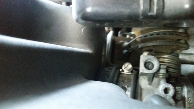
Yeah, I am not spending that for a scanner. I have a scanner that does basics, but just does not have enough features to get all fancy. Problem I would have anyway is even if I had a couple thousand dollar scanner I would have to track down and most likely pay for the date/perimeters I am looking for in each sensor for every vehicle I am working on, and it is just too much. Guess I will replace the MAP sensor when it arrives, if that does not fix it then I will flip a coin to see if I take it somewhere, or risk replacing the cam and crank sensors. Here is that idle screw. I know for a fact that i's what it is cause I have had the throttle body off and it does adjust the position of the throttle blade.
Was this
answer
helpful?
Yes
No
Sunday, December 9th, 2018 AT 8:14 PM
Tiny
ONEPHAT66
  • MEMBER
  • 20 POSTS
The picture I sent ended up sideways, but you can see the torx tip screw in the "U" shaped casting.
Was this
answer
helpful?
Yes
No
Sunday, December 9th, 2018 AT 8:15 PM
Tiny
CARADIODOC
  • MECHANIC
  • 33,742 POSTS
Boy, I can't argue with what you found, but I have never run into that. The problem still remains that it is only going to adjust air, not fuel, so I would treat it like those older imports and adjust it so idle speed is too low, say around 500 rpm. If you adjust it too high, you are just creating a larger controlled vacuum leak. That will raise engine speed, but without that corresponding increase in power. The Engine Computer is going to respond by trying to lower idle speed back down, and it does its thing by closing the AIS motor and shortening the pulse time of the injectors. The actual position of the AIS motor is not monitored in any way, so the computer just assumes it knows it's open too far, and tries to close it. If you start out with idle speed adjusted up too far, the computer will keep on pulsing the AIS motor to close more, and more, ... And more, without achieving the desired results. Problem is, each time it does that, it knows it is supposed to reduce fuel too at the same time. It thinks it's reducing air and fuel to lower idle speed, but you're artificially holding air and idle speed up too high, and the computer doesn't know that.

When you start with that idle screw too low, and once minimum throttle has been learned, the computer will open the AIS valve and increase injector on-time in unison to adjust idle speed. At that point the fuel / air mixture will be correct and there will be no stumbling or idle speed hunting. From normal driving, the computer will see from the front oxygen sensor if the fuel / air mixture is less than perfect, and it will fine tune it automatically. You can see what it has been doing by looking at the "short-term fuel trim", (STFT), and the "long-term fuel trim, (LTFT) numbers on the scanner.

Starting out with base idle speed much too low is a throwback to the carburetor days when dieseling was a common problem. A solenoid turned on to set idle speed, then it turned off and relaxed to let idle speed drop way too low to prevent dieseling when the engine was turned off. With cars as new as yours, the computer needs to be able to adjust idle speed to make up for a variety of conditions, and if base idle started out at 800 rpm, then went up for some reason, the computer wouldn't be able to lower it back down.

As a point of interest, if you pull that AIS motor out and watch the pintle valve, you will see it extend all the way out, then retract a little when you turn the ignition switch on. Some models extend it when you turn the ignition switch off, and you can hear that if you're under the hood. Some models extend it when you turn the ignition switch on. The point is the computer pulses it enough to insure it is fully-closed, so it knows where it is starting from, then it retracts it roughly 50 steps. That is what gives you the nice "idle flare-up" to 1500 rpm at start-up for a few seconds. If I forgot to mention that, the lack of that idle flare-up is another clue that minimum throttle has not been relearned.

As for the scanners, everything we've covered so far is not a high-end feature. There are a lot of nice units around now for under $100.00 that do provide sensor data, but those are not true scanners. Those are just real high-class code readers. I have a few of them and I've found that the sensor readings update about once every two to four seconds. That is way, way, way too slow to be of any use when looking for intermittent glitches. All the better scanners update their data many times per second.

I'm not sure what you're referring to by;

"Problem I would have anyway is even if I had a couple thousand $$$ scanner I'd have to track down and most likely pay for the date/perimeters I'm looking for in each sensor for every vehicle I'm working on".

Once you own the scanner, the only cost is to update it if you want to. I had former students update mine at the dealership I used to work at, but there are no more updates for that one. A DRB3 or an out-of-date Solus Edge would work very nicely for you, for much less than $1000.00. The Solus will handle every U.S. Car brand up to the latest update year installed in it, and European or Asian imports only if that software package had been purchased. Most people at least bough the Asian software.

The first version of DRB3 will plug right into your car and any other '96 or newer Chrysler product up to at least 2003. The newer version like I have only works back to 1998 models on its own. Both versions can have a little card plugged in at the bottom, then they will work on '94 and newer models, and that card gives it the capability to do emissions stuff on all brands of cars, as I mentioned earlier. A different card lets it work on '83 and newer cars, but only Chrysler products.

All of these scanners are "bidirectional" too, meaning you can talk back to the computers to command them to do things, or to reprogram various features. Once you use one and see half of what they can do, you'll never want to be without one.
Was this
answer
helpful?
Yes
No
Monday, December 10th, 2018 AT 12:20 AM
Tiny
ONEPHAT66
  • MEMBER
  • 20 POSTS
Well I guess I'll have to look into these DRB3 scanners. Mine is a scanner/code reader (Actron 9580 if I remember correctly), which I know isn't real fancy. What I was implying about paying the extra to update the DRB3's you were referring to is I figured it would cost to update some of these due to the complexity/"fancy-ness" of these scanners. Mine didn't cost anything, but it's not a "fancy" scanner by any means. I also mentioned I would have to find the correct data points to bounce my findings off of if I had a scanner that would do more I figured, as it's not easy just searching the web for these data numbers, so I figured I would have to pay to get the info, kinda like the Alldata idea. Now if this type of info is available and didn't cost every time I needed it, or an annual cost it wouldn't be a big deal. I just didn't want to get a new, fancy scanner and not have the data points to reference what I was finding when using it. For example, if I was reading the step data you mentioned a few days ago when discussing the IAC, if a person can scan and read the data, but doesn't know what the acceptable range is, the "fancy scanner" does you no good. I've actually been looking at a much nicer, upgraded scanner that will do much more than my current scanner, but with the holidays it wasn't the right time to jump into that. Even if we get this problem figured out without the new scanner, I still plan to purchase one after the holidays. I do really appreciate the help, just very limited to my scanning abilities at the moment. I did scan the car yesterday and noticed the MAP position was stuck on 31 "hg, regardless of the RPM. Since trying to clean the current MAP sensor it's been running even worse, (if a person can believe that), but I believe it's due to dislodging a piece of carbon and clogging to port, therefore creating a false reading. I hope the new sensor fixes that as well as everything else, but I'm not holding my breath. I also got a code P0108, which I assume if due to me trying to clean the MAP sensor. It will clear, but comes back within seconds of restarting, so I'll wait till new sensor is installed. Unless you have some further ideas prior to the new sensor, I'll just wait to receive and install new sensor and give updated info. Thanks.
Was this
answer
helpful?
Yes
No
Monday, December 10th, 2018 AT 6:06 AM
Tiny
CARADIODOC
  • MECHANIC
  • 33,742 POSTS
You're at the right place. I can help with every sensor other than mass air flow sensors. Other experts will come to the rescue when necessary. The scanners display a sensor's signal voltage, but then they also show the value the computer interprets that to be. You don't have to guess, for example, if 3.5 volts is correct for the coolant temperature sensor. It will show right under that, "194 degrees F".

It takes too long to type all the information regarding sensors and scanners. A better solution is to find copies of Chrysler's training manuals. I always picked up a pile of extras when I went to their training classes. Also, my community college was one of three remote training sites they used around Wisconsin, and at the end of the week, they left us all their extra books. Their basic electrical class took two days. I can boil down all the important points very quickly. Besides training books, they offer a lot of diagnostic manuals that complement the service manuals, but are completely different. They are designed mostly for diagnosing fault codes with their DRB3. I never allowed my students to use those books because they are designed with technicians in mind who do not have a good understanding of electrical theory. My kids learned how a circuit worked, then they could figure out how to diagnose it without a book to guide them. Most of the charts in these books use truth tables, meaning it asks you to take a reading or observation, then answer, "yes" or "no", and follow the appropriate path to the next question. You don't need a chart like that when you know what voltage to expect at a point at what time.

Lets start tonight with the MAP sensor code 108. I described a while ago how they're built and how accurate they are. The original design's problem was caused by the protective jelly around the circuitry being eaten away by gasoline fumes. The biggest culprit was when an owner filled the gas tank on a really hot day, and squeezed and squeezed more fuel in after the pump had kicked off a number of times, and then they drove a few blocks and parked the car. You had to do every one of those things repeatedly to cause the problem. The cold gas from underground tanks would get hot and expand in the tank unless the car was driven a good 20 -50 miles. As it expanded, those fumes were collected in the charcoal canister, and overwhelmed it, then they made their way into the intake manifold and up to the MAP sensor where the protective jelly dissolved, then the fumes attacked the exposed circuitry. The redesigned sensor didn't seem to have that problem, and in fact, they are pretty reliable now.

The sensor is fed with 5.0 volts, and the ground return is shared with a number of other sensors. That circuit goes to ground through the Engine Computer so it can be monitored. For that reason, you will find 0.2 volts on the ground wire, not the 0.0 volts you might expect. The acceptable signal voltage range is 0.5 to 4.5 volts, but in actual practice, you'll typically find it to be around 1.2 to 4.2 volts. The exact values aren't important. What is important is if the ground wire is broken, or there's a problem in the sensor's circuitry, the signal voltage will go to 5.0 volts. That will trigger the fault code, "MAP voltage too high", which is what you have.

If the 5.0 volt feed wire is open, the signal voltage will be 0.2 volts. The tough one to understand is a break in the signal wire. If the wire is cut, the sensor will still work, and you'll find the correct voltage at the sensor's connector, but in the computer, that wire is interconnected to all kinds of circuitry, so what the computer sees can "float" to some random value. If that was a value within the acceptable range, the computer will accept it and try to run on it. It does also correlate the readings with other sensor readings and operating conditions, and it can set a different fault code referring to a disagreement. For example, it knows if it's firing the ignition coils at a rate of 5,000 rpm, and the throttle position sensor says it's at idle, those two things can't both be true. A MAP sensor can't say you're coasting when the throttle is wide open. Those set different kinds of fault codes where you have to figure out which one is wrong.

To prevent the signal voltage from floating to a random value when the signal wire is open, all of these circuits have an internal "pull-up" or "pull-down" resistor connected to them. Most common is the pull-up resistor. It is of such an extremely high resistance that under normal operation, it's like it isn't even there. It has no affect on the signal voltage. However, when that signal wire is cut, that pull-up resistor is tied to the internal 5.0 volt supply, so it puts 5.0 volts on the signal wire to force a defective condition to be detected, and a fault code to be set. Many people will just assume the sensor is bad, then they are stumped when the new one doesn't solve the problem. This would be found by first taking a couple of voltage readings before ordering the new part. You would find 5.0 volts on the scanner, and 5.0 volts at the terminal in the computer's connector, if you wanted to go through all that work of getting to it, but you'd find a correct voltage at the sensor. With two different readings at each end of the signal wire, you would know to suspect the wire, not the sensor.

A pull-down resistor is tied to ground, so a cut wire for that sensor would set the fault code, "voltage too low". You can determine how your circuit works by unplugging the sensor when the ignition switch is on, and measuring the voltage on the signal wire in the plug. Most often you'll find 5.0 volts.

When you first turn on the ignition switch, the MAP voltage represents barometric pressure. The computer puts that in memory, and updates it each ignition switch cycle. Years ago GM had a lot of trouble with them going out-of-range when you drove up or down a mountain. They couldn't handle the wide change in barometric pressure. All you had to do when the Check Engine light came on was to stop the engine, then restart it. The fault code would still be there, but the light would go off. Those codes on Chrysler products self-erase after 50 engine starts if they don't act up again.

As soon as the engine starts running, manifold vacuum goes up and that draws the MAP signal voltage down. I'd expect to see around 1.5 volts. Under load or heavy acceleration when the throttle blade is open, vacuum goes away, and MAP voltage goes up to perhaps 3.5 to maybe 4.0 volts. During coasting, vacuum is higher than normal, and MAP voltage is lower than normal. That is one of the parameter the computer is looking for to memorize minimum throttle.

There are some variations to be aware of with other car brands. Everyone else other than Chrysler uses a mass air flow sensor as the major contributor for fuel metering calculations. They usually still have a MAP sensor, but it is only used to read barometric pressure, and that continuously updates as you drive. Many GM models, and I'm sure many other brands, will use their MAP sensors as a back-up strategy for fuel metering when a defect is detected with their mass air flow circuits. Most of those engines will run quite well on the MAP sensor.

Chrysler uses a different method which is also common to other sensors on other car brands. This is what you might be running into with yours. When the computer detects a problem with the MAP circuit or the signal voltages it is receiving, it knows it can't trust those values, but it wants to keep running the engine. It can disregard the suspect signal voltage, and "inject" an approximate value to run on. Lets say the 5.0 volt feed terminal is spread in the connector and not making good contact. The computer will see 0.2 volts and set a fault code, but it knows the engine is running, and how fast, by the injectors and ignition coils it is firing. It sees the signal pulses coming from the cam and crank sensors. It knows road speed as it gets that data from the Transmission Computer and its speed sensors. It knows throttle position, so based on all of those things, it knows that MAP voltage should be very close to, ... Oh, ...2.784 volts. That is the value it will inject to use for that part of the fuel calculations. It won't be perfect, but it can be so good that people ignore the Check Engine light and keep on driving.

Here's what can happen though. You have a sensor that is just starting to fail, or there's condensed gas in the vacuum hose, or there's a large vacuum leak that causes manifold vacuum to drop. Any of those will result in the sensor developing the wrong signal voltage, but it is still within the acceptable range. The computer will accept them and run on them, but the engine will run poorly. Now you come along and unplug the MAP sensor. The computer will immediately detect that, set the fault code, turn on the Check Engine light since the code refers to something that could adversely affect emissions, and it injects the value it expected to see. With that injected value, the engine runs well, or at least better. We read this very often where someone says the engine runs worse when they plug in a new sensor.

There's two clinkers to this story you should be aware of to avoid arguments with your friends. The first one refers to some Nissan engines from the '90s, and possibly some others. Some of those engines used a MAP sensor that developed a low voltage for low vacuum / engine not running, and it went higher as vacuum went higher. With most sensors, it was the opposite. Voltage starts out high and goes down as vacuum goes up. Nissan had models that used one style or the other, and they both looked the same, mounted the same, and used the same plugs. If you had a used sensor on the shelf that you used for testing, you could put the wrong one in. I don't remember what the symptoms were, but this was found by a fellow who owns a shop that specializes in solving the one in a hundred cars that no one else can figure out. He is in Joliet, IL. He develops classes around these elusive problems, and came to our school once a month for the independent mechanics in my town. I got to sit in on those classes. Most of his customers are other shops, and he charges the same flat fee for every car, regardless how long it takes.

The second problem is more frustrating because it happens without any mistake on the mechanic's part. To my knowledge this only applies to GM vehicles in the '90s. Their dealer-level scanner was the Tech2. I don't know if this applies to other brands. The problem was when the Engine Computer knew there was a problem with a sensor and it injected a value to run on, it was that injected value that showed up on the scanner's display. For example, if you unplug the throttle position sensor, the pull-up resistor would take the signal voltage to 5.0 volts. That is what you would measure at the TPS connector, at the computer's connector, and it is what you should see on the scanner. However, the computer injected, lets say, .822 volts at idle, which is a value you could expect to see. How is it you have a perfect signal voltage, yet you have a recurring fault code for "TPS voltage too high"?

I suspect that was a software oversight in the Engine Computer, because the scanner is just displaying the data it was sent by the computer. The only fix for that was to be aware of it and share that with as many people as possible.

Remember when I mentioned how sensitive these MAP sensors are? There is another fault code that can be set for "pneumatic failure". There were some K-cars in the '80s that had the sensor mounted on the right strut tower, and a real long vacuum hose going to it. Gas fumes would condense and pool in a low spot where that hose drooped. The sensor itself still worked, but the liquid partially-blocked, and dampened the pulses of vacuum. Even though the signal voltage changed rapidly, like it was supposed to, the computer set this code because it wasn't seeing those tiny pulses. If those were missing, what else might be wrong, so it set the code, "pneumatic failure".

Another common one is "no change in MAP from "start" to "run". This was the typical code for those early failed sensors. The gas fumes destroyed the rubber diaphragm that tugged on the piezoelectric crystal. That crystal was at rest, like normal, when the ignition switch was turned on, so it sent out the correct signal voltage, but once the engine started and vacuum was developed, there was no diaphragm to pull on the crystal, so no change took place in signal voltage.

Now you know as much as I do about MAP sensors. Many of the others work on similar principles with the same range of signal voltages. Temperature sensor circuits are considerably simpler, but they need a slightly different description. Let me know when you need that great and wondrous information.
Was this
answer
helpful?
Yes
No
Monday, December 10th, 2018 AT 5:46 PM
Tiny
ONEPHAT66
  • MEMBER
  • 20 POSTS
Okay, I changed the MAP sensor yesterday and it runs and idles much better. It is still hunting for an idle, but not near as bad, the P0108 code hasn't returned yet either. It hasn't shut off yet while idling, but it may be a little early to get too excited. So you thinking the cam/crank sensors to further improve the idle hunting issue?
Was this
answer
helpful?
Yes
No
Saturday, December 15th, 2018 AT 9:21 AM
Tiny
CARADIODOC
  • MECHANIC
  • 33,742 POSTS
No. Those sensor develop a different kind of signal that is either good or bad, but it is often intermittent. If the engine runs, both of those sensors are working.

It's the MAP sensor and on cars that use a mass air flow sensor, that can develop an incorrect signal voltage, and since they are the main ones for fuel calculations, they cause the most of these elusive problems. The throttle position sensor is a simple mechanical sensor, very similar to the fuel level sensor in the gas tank. It uses a metal tab that slides along a carbon resistor element. I suppose the rivets holding that tab could become loose, but that resistor isn't going to change on its own.

The cam and crank sensors develop "square wave" signals that switch between "off" and "on", or "high" and "low". The signals change state between approximately 0.2 volts and 4.8 volts. In some applications, the Engine Computer just looks at the frequency. That is accurate enough for timing injector pulses. Timing for ignition coils must be much more precise. For those applications, the computer looks at the "rise time", meaning the instant the signal switches from 0 to 5 volts, or it may look at the "fall time" where it switches back to 0 volts. One characteristic of these sensors on all car brands, since there is a lot of delicate circuitry inside them, is they start to fail by becoming heat-sensitive, then they work again after cooling down for an hour. Usually they don't just suddenly fail or suddenly start to work. If you'd watch their signals on an oscilloscope, you would see the signal not make it all the way down to 0 volts or up to 5 volts. It might go from 0.5 to 4.2 volts, for example, then as it gets hotter, that drops to 0.6 volts to 3.2 volts. All computer circuits work with these digital signals that have only two states, and while they are designed to recognize 0 and 5 volts, to improve stability, there is always a range of voltage that will still be considered acceptable. One computer might read 3.8 volts as "high", while another computer might require it to be 3.85 volts to be recognized. That range in between is "no man's land" where the voltage has no meaning, and the computer doesn't know if it should be interpreted as "high" or "low". At that point, it stops seeing the signal and it considers it to be missing.

The other way these fail is identical to if you unplugged them. The voltage on the signal wire will get pulled up to 5.0 volts or down to 0.0 volts, and it will sit there.

To add to the confusion, once an engine is running, if one sensor fails, the computer knows the engine is still rotating by the presence of the pulses from the other sensor. If the failed sensor was used to time ignition coils, the computer can switch to a back-up strategy where it times them from the other sensor, but with less precision. Once you stop the engine, the computer needs both signals to restart it because it has to know which ignition coil to fire first. On some GM models, you had a 33 percent chance a V-6 engine would restart, if it picked the right pair of cylinders to fire first. If it guessed wrong, it would continue to incorrectly count them out in order, and continue to fire them at the wrong times, until you turned the ignition switch all the way off, then tried again to start the engine. Each time you turned it on, the computer started out with cylinder number 1 and its mate. If it was one of those two pistons that were just coming up on the compression stroke, the engine would start and run. Chrysler Engine Computers started working similar to that around the 2001 or 2002 model years. Before that, both signals had to be there during cranking, then the computer would turn on the ASD relay to power up the coils, injectors, fuel pump, etc.

The only other thing that can go wrong with these position sensors on some applications is they have the wrong air gap. I had one where I was "too smart" to need the special paper spacer that set that gap. That car came back two weeks later with an intermittent stalling problem and a fault code for the missing signal. Simply reinstalling it with the special spacer solved that problem.

To sum this up for these two sensors, they are working or they are not working, and the engine will run or it won't run. This is a big generalization, but for the most part, these do not cause objectionable performance issues like a MAP sensor can. All the other temperature sensors, front oxygen sensors, TPS, MAP, and mass air flow sensor signals are used to calculate the amount of fuel needed right now. The cam and crank sensor signals are used strictly for when to fire an injector or coil.
Was this
answer
helpful?
Yes
No
Saturday, December 15th, 2018 AT 8:32 PM

Please login or register to post a reply.

Sponsored links