Here are procedures for ignition checks.
IGNITION CHECKS
DISTRIBUTOR IGNITION
To determine cause of no-spark condition, perform following tests in order given. Deviation from this procedure may cause false diagnosis and replacement of non-defective components.
Spark
Check for spark at coil wire and each spark plug wire using spark tester. DO NOT crank engine continuously for more than 2 seconds. Inspect secondary coil wire for arcing while testing spark at plugs. Check electrical connections at Camshaft Position (CMP) sensor, ignition coil and power transistor.
Ignition Coil Power Source
1. Disconnect ignition coil 2-pin connector. Turn ignition on. Check for voltage at Black/White wire terminal.
2. If voltage is present, go to POWER TRANSISTOR. If voltage is not present, check continuity of entire circuit between battery and ignition coil, including fusible link and ignition switch.
Power Transistor
For power transistor system testing, see DTC 21 - IGNITION SIGNAL in the TESTS W/CODES article. For power transistor component testing, see IGNITION SYSTEMS in SYSTEM/COMPONENT TESTS article.
Ignition Coil Resistance
1. If ignition coil malfunction is suspected, carefully inspect external housing for burned spots indicating secondary circuit arcing to primary or ground circuits. Disconnect ignition coil primary 2-pin connector.
2. Using an ohmmeter, check resistance between primary connector terminals. Check resistance between secondary tower and positive terminal (Black/White wire) of coil primary connector. If either resistance is not as specified, replace ignition coil.
V6 IGNITION COIL RESISTANCE
Primary = 1/0 Ohms @ 68°F (20°C)
Secondary = 10,000 Ohms @ 68°F (20°C)
Camshaft Position (CMP) Sensor
1. CMP sensor is located inside distributor. If a fault is present in CMP sensor, Code 11 may be set in ECM memory. If Code 11 is set, perform DTC 11 - CMP SENSOR in the TESTS W/CODES article.
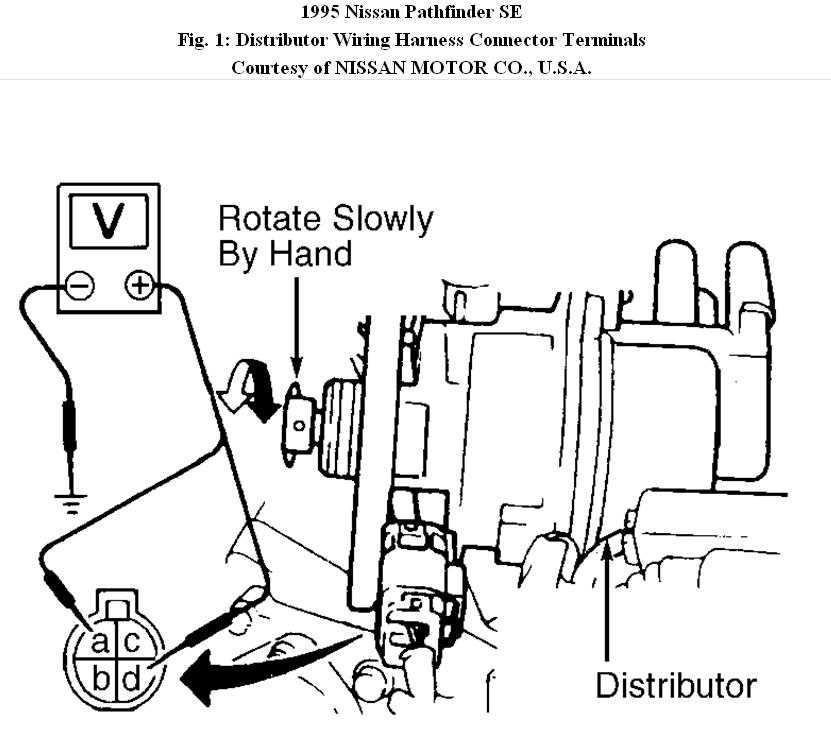
2. To test CMP sensor, remove distributor. Leave wiring harness connected. Using a voltmeter, connect negative lead to ground and alternately connect positive lead to 1-degree signal terminal and 120/180-degree signal terminal. See CMP SENSOR INPUT SIGNAL TERMINALS table. See Fig. 1.
3. Measure voltages at both terminals while rotating distributor by hand. Voltage should fluctuate between 0-5 volts. If either voltage signal does not fluctuate between 0-5 volts, check harness for short or open circuit. If no problems are found, replace CMP sensor.
CMP SENSOR INPUT SIGNAL TERMINALS
1-Degree Signal = Terminal # 4.
120/180-Degree Signal = TErminal # 3.
Image (Click to make bigger)
Wednesday, January 12th, 2011 AT 4:30 PM