Replacement speakers might be "better", but original speakers are tailored to the specific vehicle. That's why two different models can have identical-looking and size speakers but they have different part numbers.
Here's version two of last night's reply that vaporized:
Back in the days of 8-tracks, speakers had one terminal grounded, and the audio signal showed up on the other wire. The problem with running the audio amps on 12 volts is while you can generate up to a 12 volt AC signal, the midpoint, which equates to the lowest signal level, would have to be 6 volts. No speaker would take that for very long. As the signal gets louder and the size of the sine wave gets taller, the voltage going to the speaker increases and decreases but never stays at 0 volts. Current is always going the same way, it just varies up and down. There will always be some DC voltage across the voice coil except for the very brief and rare moments when it goes to 0 volts. For those moments there will be a matching period of 12 volts. Regardless, the average is 6 volts which keeps the voice coil off-center.
That alone leads to distortion because the further the speaker cone moves, the more resistance to that movement builds, so it moves a smaller and smaller additional amount as the voltage increases linearly. The opposite is true when the voltage goes toward 0 volts. The speaker cone wants to return to its resting position anyway, and the drop in voltage allows it to do that very easily. To say this a different way, when the signal voltage rises from 6 to 9 volts, the speaker cone is going to move considerably less than when the voltage drops from 6 to 3 volts. While the sine wave might be perfectly clean with no distortion, the mechanical response of the speaker cone will not produce a matching audio waveform. It can't help but introduce distortion due to a mechanical limitation.
To address that, most manufacturers used an audio output transformer. That allowed an internal regulated voltage to be applied to the final transistor stage through the transformer's primary winding, which also presented enough resistance to limit current to safe design values, and that transistor would not introduce any distortion. You understand transistor theory, so for example, lets say the base has 3 volts at idle, (no audio signal present), and the collector has 6 volts. Now a very low audio signal shows up with a sine wave that's one tenth of a volt high. When the base voltage goes from 3.00 to 3.05 volts, the collector's voltage may drop one volt to 5.00 volts. During the other half of the signal, when the base voltage goes from 3.00 volts to 2.95 volts, the collector voltage will go to 7.00 volts. The one volt rise and one volt drop match the linear .05 volt rise and .05 volt drop at the base. That was never the issue before, but having the transformer allowed the use of a circuit that didn't introduce any distortion, while making a signal voltage available to the speaker that would allow that speaker to do its thing, also without introducing its distortion.
The secondary winding of the transformer simply puts out an AC voltage matching what went in, except now, instead of the current going to the speaker rising and falling but always going the same way, (and the speaker cone always averaging an off-center condition), this is now a clean AC signal with no DC component to it. That means that with no signal voltage, the speaker cone is centered and at rest. When a sine wave is presented, for half of the cycle, the speaker cone stretches out, and the other half cycle the cone stretches in. The forces are equal so no mechanical distortion is created.
Eventually everything started to become lighter and lighter. Even tvs lost their ten-pound power transformers. By the early to mid '80s most car radio manufacturers had gone to an integrated circuit for the final amplifier stage, but they combined the best of both worlds. There is no DC voltage holding the speaker's voice coil off-center, and there's no pair of heavy audio output transformers. They do that by placing approximately 6 volts on both speaker wires, and applying equal but opposite signals on the two wires. The most common output ICs have a pair of stages for each speaker, one stage for each wire. The DC voltage sits at 6 volts, then up to a 12 volt AC sine wave can be impressed on top of that, so the voltage can vary from 0 to 12 volts. At the same time the inverse is occurring on the other wire. That means that with two 12 volt AC signals, and one is inversed, the speaker will actually see up to a 24 volt AC voltage. You could achieve that with a transformer too, along with the weight and high manufacturing cost. At first this doesn't sound right, but if you look at both signals on a dual-trace oscilloscope with an "add" function, you'll see the one combined signal has twice the amplitude as either individual signal. (I have one more wondrous detail about this at the end of my marvelous story).
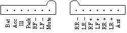
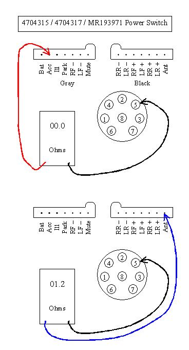
That's why you'll find 6 volts on all speaker wires in cars today. My voltages in this story are just approximate to illustrate the important points, but they're pretty close. Since nothing associated electrically with the speaker is grounded, and both terminals have exactly the same DC voltage, the voice coil sees only the 0 volt difference and not the 6 volts on each wire, so the voice coil stays centered when there's no AC signal voltage.
Most manufacturers use a pair of output ICs, and each one has four identical amplifier circuits. Two are for the pair of speaker wires for the right front speaker, and two are for the pair of wires for the right rear speaker. The second IC is used the same way for the pair of rear speakers. The radio I mentioned that had short detection was one of the rare models that used one IC for the front speakers and the other for the rear speakers. Almost all other radios split the job between left and right.
GM, true to their habit of developing customer-unfriendly business practices that put profits ahead of their customers' best interest, developed a proprietary output IC that cost well over $20.00, and they were almost impossible to harvest from a donor radio without destroying them physically or by overheating them. They stopped making those a long time ago, but they must have allowed some other manufacturer to take over production because I was able to buy them the last time I needed some. The new replacements have a higher volume, so if you only replace one, there is a minor modification that needs to be made to cut the output to match the other IC. By the way, almost all ICs in GM radios are proprietary and had to come from their parts suppliers.
Chrysler always used generic output ICs that were already developed for the home entertainment industry, so they had a known track record. Often they had in-house part numbers, but those numbers were in most cross reference guides, and the generic numbers were listed in their radio service manuals. The more expensive ones cost me $2.50 each.
In the early high-end radios of the late '80s, many of them used four output ICs but they worked the same way. Before this, front-to-rear faders were mechanical controls, usually a rheostat or wire-wound potentiometer that split the current between two speakers, a front one and a rear one. Those radios were built with two audio channels, a left and a right channel, then the fader was added to handle two more speakers.
It was easy to design in four channels right away when output ICs were used, but the balance and fader functions got rather involved because each amplifier stage needed the incoming signal to be attenuated to adjust its volume level based on the settings of the balance, fader, and volume controls. It didn't take long before they started using ICs with amplifier stages where each ones' volume was adjusted by varying a clean and steady DC voltage on a pin of that IC. That made two things possible that Chrysler exploited. One was the up and down volume pushbuttons that allowed you to change volume by just holding a switch, and the other was the balance / fader joystick.
I promised to expand on that 24 volt AC signal novel. Once you are done checking for six volts on all of your speaker wires, and if that is okay, ideally your next step is to look at the signals with an oscilloscope. This is where I got "all wrapped around the axle" about 25 years ago. The radio had one dead speaker. The other three worked fine. I had a four-trace scope so I was watching both wires going to a working speaker, and the pair going to the dead speaker. All four had close to six volts, all four had identical waveforms, and all four waveforms could be varied for volume and balance. The only possible explanation was I had a bad speaker on my test bench. I didn't notice that one waveform didn't respond to volume adjustments like the others did.
Apparently the wind through my ears blew the candle out, because it wasn't until I wasted an hour taking the bench apart and I disconnected the speaker that I noticed one of the four waveforms was missing. Closer inspection showed it had dropped to 0 volts and had no AC signal. Everything came back when I reconnected the speaker! Finally it occurred to me one of the four amplifier stages in one IC was open. The six volts and the AC signal were originating in the good stage, making it to the speaker, through it, and back to the radio where I had the second probe, but current couldn't complete the circuit through the open stage. It never dawned on me that I was seeing two identical waveforms, meaning they had the same phase, feeding the two sides of the voice coil.
To test my discovery, I jumped a fairly large electrolytic capacitor from the dead terminal to ground, and I suddenly had a working speaker, but at about half the volume of the others, then, to figure out a clue for the next time I ran into this, all it took was to use that "add" feature on the scope. There's a clinker though. With the good channel, two out-of-phase waveforms added together should have turned into a flat line, but what I found was a very tiny AC signal representing the slight changes in tone being done in one of the stages. THAT turned out to be the clue to look for. On the dead channel with the two in-phase waveforms, adding them together just produced one waveform with twice the amplitude. That alone should have told me the speaker was seeing the same thing on both terminals, which means no difference and no sound. But, when one waveform was inverted, then they were added, I got the flat line but without that microscopic AC signal. That is what represented what the speaker was seeing.
I hope all of that made sense. If you don't have a scope, and since it's faster, you might try grounding the speaker terminals, one-at-a-time, with a capacitor. That won't affect the DC voltage, but it might verify a problem in the amp that you suspect.
Dec 31, 2019 at 3:07 PM