Ok.
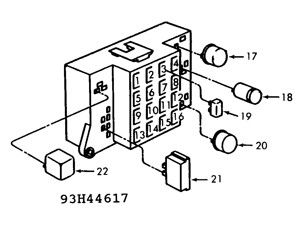
Here is the Fuse Block Layout.
IDENTIFICATION > FUSE & CIRCUIT BREAKER IDENTIFICATION > 1 - 20 Amp (Yellow)
Hazard Flasher & Turn Signals Panel Indicator, Side Marker Lights.
IDENTIFICATION > FUSE & CIRCUIT BREAKER IDENTIFICATION > 2 - 20 Amp (Yellow)
Back-Up Lights, A/C Fan & Clutch Relay Coil.
IDENTIFICATION > FUSE & CIRCUIT BREAKER IDENTIFICATION > 3 - (Blank)
Not Used.
IDENTIFICATION > FUSE & CIRCUIT BREAKER IDENTIFICATION > 4 - 30 Amp (Green)
A/C Or Heater Blower Motor.
IDENTIFICATION > FUSE & CIRCUIT BREAKER IDENTIFICATION > 5 - 20 Amp (Yellow)
Taillights, Park, Side Marker, License & Panel Lights.
IDENTIFICATION > FUSE & CIRCUIT BREAKER IDENTIFICATION > 6 - 20 Amp (Yellow)
Stoplight, Dome & Ignition Switch Light, Time Delay Relay, Courtesy Light.
IDENTIFICATION > FUSE & CIRCUIT BREAKER IDENTIFICATION > 7 - 20 Amp (Yellow)
Horn & Relay, Cigarette Lighter, Radio & Clock Memory, Key-In & Headlight Buzzer.
IDENTIFICATION > FUSE & CIRCUIT BREAKER IDENTIFICATION > 8 - (Blank)
Not Used.
IDENTIFICATION > FUSE & CIRCUIT BREAKER IDENTIFICATION > 9 - 10 Amp (Red)
Radio & Clock Power.
IDENTIFICATION > FUSE & CIRCUIT BREAKER IDENTIFICATION > 10 - 20 Amp (Yellow)
Turn Signal & Front Side Marker Lights.
IDENTIFICATION > FUSE & CIRCUIT BREAKER IDENTIFICATION > 11 - 20 Amp (Yellow)
Windshield Wiper & Washers.
IDENTIFICATION > FUSE & CIRCUIT BREAKER IDENTIFICATION > 12 - 3 Amp (Violet)
Cluster, A/C & Heater Control, Cigarette Lighter Light, Ash Tray & Radio Lights.
IDENTIFICATION > FUSE & CIRCUIT BREAKER IDENTIFICATION > 13 - 5 Amp (Tan)
Fuel Gauge, BRAKE Warning, Oil Gauge, Seat Belt Warning- Buzzer, Temp. Gauge, Volt Gauge, Speed Control, Oil & Temperature Lights, Fuel Pacer System.
IDENTIFICATION > FUSE & CIRCUIT BREAKER IDENTIFICATION > 14 - (Blank)
Not Used.
IDENTIFICATION > FUSE & CIRCUIT BREAKER IDENTIFICATION > 15 - (Blank)
Not Used.
IDENTIFICATION > FUSE & CIRCUIT BREAKER IDENTIFICATION > 16 - (Blank)
Not Used.
IDENTIFICATION > FUSE & CIRCUIT BREAKER IDENTIFICATION > 17 - Relay
Hazard Flasher Warning.
IDENTIFICATION > FUSE & CIRCUIT BREAKER IDENTIFICATION > 18 - Relay
Relay.
IDENTIFICATION > FUSE & CIRCUIT BREAKER IDENTIFICATION > 19 - Circuit Breaker
No other description.
IDENTIFICATION > FUSE & CIRCUIT BREAKER IDENTIFICATION > 20 - Relay
Turn Signal Flasher.
IDENTIFICATION > FUSE & CIRCUIT BREAKER IDENTIFICATION > 21 - Buzzer
Warning.
IDENTIFICATION > FUSE & CIRCUIT BREAKER IDENTIFICATION > 22 - Relay
Horn.
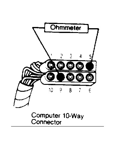
Image (Click to make bigger)
Friday, March 28th, 2014 AT 1:43 PM