Front suspension replacement

Tiny
ROB 1503
  • MEMBER
  • 1987 CHEVROLET BLAZER
  • 2.5L
  • V6
  • 2WD
  • AUTOMATIC
  • 198,000 MILES
Hi,

A friend of mine recently bought herself the vehicle listed above (s10) and came to me asking if I could check out a squeaking noise coming from front suspension. Right away I noticed that all her ball joints and related parts were extremely rusted and didn't have boots or grease. So she asked me if I could change them for her. I've done ball joints and a few other components but not center links, tie rod adjusting sleeves or idler arm. So I was wondering if anyone could help me out with instructions on how to replace the following parts listed below and torque specs?

1 Center Link
2 Tie Rod Adjusting Sleeve
2 Front Outer Tie Rod End
2 Front Inner Tie Rod End
2 Front Upper Ball Joints
2 Front Sway Bar End Link
2 Front Lower Ball Joints
1 Idler Arm

Thank you
Tuesday, November 19th, 2019 AT 9:02 PM

13 Replies

Tiny
CARADIODOC
  • MECHANIC
  • 33,752 POSTS
This is going to involve a real lot of typing, and it still won't do it justice compared to watching someone do these tasks while describing them. I can supply you with a textbook, but even that isn't much better than reading through the instructions in the service manual. I'm going to work on a proper reply tonight, then I'll post if for you tomorrow if someone else doesn't post something better first.

In the meantime, if you're going to be asked to work on this vehicle in the future, look on eBay for a copy of the manufacturer's paper service manual. Those will do a much better job compared to Haynes or Chiltons manuals. Those aftermarket books assume you already know how to do these jobs, and they don't have much of value to add.
Was this
answer
helpful?
Yes
No
Wednesday, November 20th, 2019 AT 7:35 PM
Tiny
ROB 1503
  • MEMBER
  • 63 POSTS
Thank you so much.
Was this
answer
helpful?
Yes
No
Wednesday, November 20th, 2019 AT 9:05 PM
Tiny
CARADIODOC
  • MECHANIC
  • 33,752 POSTS
Lower Ball Joints

The 2-wheel-drive and four-wheel-drive trucks use different styles of lower joints. The four-wheel-drive uses a joint that looks and mounts similar to the upper joint, but they are different part numbers. That's because one of them has to be the "load-carrying" joint. In this case it's the lower joint, as it is with most models except some Ford car models up to the mid '70s. The spring pushes down on the lower control arm, then that force is transferred through the lower ball joint, through the spindle, then the wheel and tire, to the ground. That force is what holds up the corner of the vehicle. All of that load is being supported by the lower ball joint, so it has to be built strong enough to support that weight.

The first step for removal is to remove the nut, then break the connection between the tapered stud and the hole in the spindle. The new joint should come with a new nut. If it does, the old one can be discarded, so to make the job easier, you can use it to shear off the old cotter pin. Those cotter pins usually get impacted with dirt and rust, and they'll break if you pull too hard on them. Just shear 'em off since all those parts are going to be discarded anyway.

There are tools made for pushing on the end of the stud, but professionals rarely need to resort to using them. The best way to get the stud loose is to use a large hammer and pound on the spindle, just to the side of the stud. Those spindles are much too hard for you to worry about deforming them, but the shock will loosen the stud. Be ready with a means of support under the control arm as the spring is going to slap it down with a lot of force. A small floor jack is preferred because you'll need it later to raise it back up to insert the new stud. On many models you'll need to loosen the wheel bearings so the rotor can be moved out of the way, and on some models the outer-most lip of the control arm will catch on the brake dust shield. This especially must be avoided on Ford products because their dust shields are plastic and will shatter.

You're going to need a ball joint press for this type of lower joint. It is nothing more than a really beefy c-clamp with a selection of discs and cones. You can buy this tool at Harbor Freight Tools or any auto parts store, and very likely you can borrow it from an auto parts store that rents or borrows tools. In my city, they charge you for the tool, then you get a full refund when you take it back. If you decide to keep a tool, you still return that used one, then they order or give you a brand new one.

The second photo shows the most common version of this tool. Other, more-expensive sets have a larger variety of cones and discs for special applications. To press the old joint out, select the cone that just fits over the lower lip of the joint, as shown by the two pink dashed lines. This cone pushes against the lower control arm, and the joint slides through it as it comes out. The disc in the lower right corner of the red case sits on the bottom of the cone and has a matching step to keep it centered. The pushing screw pushes against this disc.

The other end of the c-clamp pulls on the disc shown in the lower left corner of the case. That disc has a hole in the center large enough for the ball joint's stud to pass through. That lets the disc rest on the housing of the joint and put pressure on it. It will be less-cumbersome if you can pry the dust boot off to get it out of the way, but if that is too difficult, just drop the disc over it and let it crush the boot. The disc will be sitting on the joint's housing where the two blue arrows are pointing. As you tighten the clamp, the joint will be pushed out, and it will drop into the cone.

The same discs are used to press the new joint in, but you'll likely need a different-size cone, and it goes on top now, to make room for the housing to be pulled in. The disc with the small hole goes on the bottom, as before, but with no cone. That disc has two sides, and you must choose the side that makes contact with the housing at its outer lip, as shown with the green arrow. It must not push on the raised area shown with the red arrow. Pushing there will deform the gold plate in the center of the housing. That plate is what holds the spring and / or nylon insert that holds pressure on the ball. If that plate becomes bent or bulged outward, the joint must be replaced. Most of the time hitting that ridge can't be avoided, then you'll need to insert one of the other cones between the disc and the joint. One of the cones will fit right around the bulge and push on the lip, (green arrow).

One fairly common problem you may encounter with this pressed-in design is the joint slides in with very little or no effort, then falls back out. The proper repair for that is to replace the lower control arm with one where that hole is not stretched, but instead, it is common practice to add two or three tack-welds to hold it in place. Those welds can easily be chiseled off next time, and in this application, the forces are pulling on the joint to keep it in place. The welds just insure the joint won't start to wobble around and wear the hole even more. Wire-feed welders work best because they get the job done fast enough to prevent melting the nylon insert in the joint.

Wipe out the hole in the spindle to insure no dirt is in there that will prevent proper tightening. Also, do not use any type of grease or anti-seize compound. The goal is for that stud to become wedged tightly in place. Slide the dust boot in place, then jack the arm up while guiding the stud through the hole in the spindle. Before you install the nut, check to see if all you can see of the stud sticking out the top has threads on it. In a few applications, you may see part of the smooth taper peeking out. Obviously, with no threads on that part, the nut can't be expected to tighten down sufficiently against the spindle. When that is a possibility, the joint will have been supplied with two or three large washers for spacers. Drop as many on there as needed so the nut won't run out of threads. If your new joint didn't come with those spacers, that manufacturer built two different versions of that joint, with different part numbers for those different applications.

Tighten the nut to specs, then, as is with any castle nut of this design, always tighten it just enough more until one of the holes lines up so the cotter pin can be inserted. Never back the nut up to loosen it to get the pin in. This also applies to the nut for the upper joint and the tie rod ends.

Upper Ball Joint

In this application, the upper ball joint is the "follower" joint, also called the "non-load-carrying" joint. It doesn't hold up any vehicle weight. It's only job is to hold the spindle upright, in perfect alignment. The smaller S10 / Blazer model is well-known for eating upper ball joints, often needing replacements every two years. As such, you can expect these have been replaced before, so you're going to find they are bolted onto the upper control arms with four nuts and bolts each. That will make removal a lot easier. The nuts that come with the replacements are lock nuts, and you may find they are so tight, the bolts are likely to snap. Be sure to use a good-quality six-point socket on the nut and the bolt head. Cheap tools are likely to round off the nuts, then the job becomes more difficult. If the nuts do unscrew, toss those bolts aside and use the new ones that come with the new joint. The old ones were stressed, and now the nuts could be more likely to work loose, or the threads could peel before you reach the torque spec. You may not find a torque spec for these in the service manual because nuts and bolts were not what GM used at the factory. There will be an instruction sheet that comes with the new joint. That will list the specified torque value for those nuts. In the absence of any written torque spec, common sense applies. These are not hardened bolts, and they don't have to withstand a lot of force. Hand-tightening with a 3/8"-drive ratchet is sufficient.

The castle nut on the stud does have a critical torque spec. That is needed to insure the stud is pulled into the tapered hole in the spindle with enough force to wedge it tight. Any time you find a stud that has popped out and is loose and wobbling around, both that ball joint and the spindle must be replaced. The hole and stud will be worn oblong to where they no longer have matching tapers. The new stud will not be supported squarely in the spindle, and if you're lucky, it will just continue to work loose. If you aren't lucky, which is more likely, the stud will snap and lead to loss of control and a crash. It snaps because it is only supported at the very end near the threads. Being of smaller diameter, that area is weaker and is not designed to withstand sideways forces. Because of the deformed hole, the stronger larger part of the stud is not resting against the spindle, so a hard shock can break it right under the threaded area.

The original upper ball joints were riveted to the control arms. Those can be very time-consuming to remove. A standard air hammer with a chisel bit won't do it. At one shop I worked at, they had a much larger air hammer that used larger-than-normal bits, but it was even a struggle with that one. You definitely needed hearing protection. Also, that hammering caused the stem of the rivet to bend and deform, making it even harder to punch them out with the air hammer. While it may take longer, it is easier to grind the heads off with an angle grinder, and then use a standard air hammer to drive the rivets out. You'll want to stick a piece of wood, or some type of block, under the control arm to prevent it from bouncing up and down as you try to punch the rivets out.

Torque Specs

Lower ball joint castle nut: 90 foot †pounds
Upper ball joint castle nut: 65 foot †pounds
Upper ball joint mounting bolts: 8 foot - pounds

Alignment

When a lower ball joint is the only part being replaced, an alignment is not required after performing this repair. The joint consists of a ball that is perfectly centered inside a hole that is perfectly centered in the housing, and that housing is perfectly centered in the hole in the control arm. While the old, worn joint may have allowed the ball to move back and forth sideways, causing "camber" to change, the new joint will put the spindle, and wheel, right back in the correct position where they would have been when the old joint was still okay. If nothing else changed over time since the last alignment, the alignment should be good now.

The upper ball joint is a different story. With any joint with this mounting style, there is never a way to insure the mounting holes were cast or drilled exactly the same. You'll also notice two of the holes in the top joint in the photo are elongated. That is to insure the bolts will drop in if there are any irregularities in the placement of the holes in the control arm. There is no way to be sure the joint's stud will be in exactly the same place as the old one was. If it's moved in or out a little, that affects "camber", the inward or outward tilt of the wheel, as viewed from in front of the truck. If the stud is moved forward or rearward a little, that affects "caster". Caster is harder to describe. Look at the angle, or "rake" of the front fork on a bicycle, and see how it angles rearward at the top. Placing weight on it is what makes the front wheel squirt out to the front and makes it possible to ride no-handed. Increasing caster during the alignment makes the vehicle track straighter with less need to constantly correct the steering wheel at higher speeds, but it makes for more steering wheel effort needed to turn corners. Up to the mid '60s, we used very low, and commonly "negative caster", meaning the upper ball joint was forward of the lower ball joint. That made it real easy to turn the steering wheel on a big, heavy truck, with no power steering. Typical highway speeds were relatively low back then. As we started driving faster, steering wander became an issue. Switching to positive caster, and increasing it, aided in stability, with less wander, but we also added power steering to make up for the greatly-increased steering effort that resulted.

Idler Arm

These are another part with a high failure rate on GM products. They don't come apart, but they develop looseness in the swivel, and that allows that end of the center link to move up and down. In fact, that is how these are checked during an inspection. I'm sure there is a spec given for how much movement is allowable, but for most of us, that is "none". When you have the vehicle on a drive-on alignment hoist with the front tires resting on turntables, when you move the idler arm up and down, you'll see the right front wheel turn left and right a little. Any visible turning movement is way too much to keep "total toe" in specs. Total toe always affects tire wear on both tires, regardless of which tire is not staying in alignment. This sets up a choppy, or "featheredge" pattern on both tires. When you run your fingertips over the tread, you'll feel it is fairly smooth one way, then you'll feel those raised sharp edges the other way. When this wear is bad enough, you'll have excessive steering wander too.

One often overlooked characteristic of center links is they must be perfectly parallel to the ground to avoid the vehicle darting off to one side when hitting small bumps in the road. Most often that causes a miserable failure to track straight down the road, and a somewhat tiring vehicle to drive. To add to the misery, there is some play in the two mounting holes in the frame for the idler arm. Before the two bolts are fully tightened, the arm can be moved up or down a little. A good habit to get into is to find a point on the ground or hoist to measure to, measure to a point on the end of the arm, then set the new idler arm to the same dimension when you tighten the bolts. Most people overlook this step, and they usually get away with it, but this, along with many other little things like this, are what keeps the vehicle handling like when it was new.

If you're replacing all the tie rod ends and center link, you don't have to separate all of them from each other. When you do need to disconnect a tie rod end, or when removing the center link requires separating a tapered stud that has to be reused, you'll want to look at the tools in the third photo. The top right one shows a "pickle fork" that is struck with a hammer repeatedly until the tapered stud pops out. This tool almost always destroys the rubber dust boot. The other tools are quieter and gentler, and are preferred, if you have them.

As with the ball joint studs, you never want to reuse any part with a tapered hole that had a loose stud in it. You won't find that very often, but if you ever do, both mating parts must be replaced.

I can't find the spec for the nut or the mounting bolts for the idler arm. Those should be listed on the sheet that comes with the new arm.

To be continued.
Was this
answer
helpful?
Yes
No
+1
Thursday, November 21st, 2019 AT 6:23 PM
Tiny
ROB 1503
  • MEMBER
  • 63 POSTS
Wow, that is a lot of typing. I'm so sorry about that. I greatly appreciate you taking the time to help me out with this. Your the best and again sorry about all that typing. I owe you big-time. So for this is great info and thank you so very much.
Was this
answer
helpful?
Yes
No
Thursday, November 21st, 2019 AT 10:03 PM
Tiny
CARADIODOC
  • MECHANIC
  • 33,752 POSTS
This is what we do here. Please tell your friends about us.

This is what I get for proof-reading only twice and not three times:

Addendum to Lower Ball Joints

If you're doing this on a hoist, you'll likely have enough clearance to use an air impact wrench and impact socket to run the pushing screw in. If you have to use a wrench or ratchet, the best approach is to run the screw down as tight as possible by hand, then give the end of the screw one nice swift crack with the hammer. The shock will break the joint free and get it to start moving. You'll probably have to repeat this multiple times, then the joint will come out easier once it's already part-way out.

Addendum to Upper Ball Joints

One more hint related to those four bolts. You should be able to fit a deep socket up under the arm to hold the heads from spinning, then use an air impact wrench to try to tighten the nuts. I've had good luck with a little 3/8"-drive butterfly impact tool to snap the bolts. This takes a lot less time than mindlessly unscrewing every nut.

Addendum at end of Upper Ball Joints

Scrub off any dirt or scale on the control arm so it doesn't get sandwiched between it and the new joint. Install the grease fittings, but don't add grease until after the joints are tightened to the spindle. The goal is only to cause the boots to balloon up a little. If grease squirts out the relief hole at the base of the boot, that is too much grease. If you find any grease inside the joint when you take it out of the box, that is just enough to prevent the parts from rusting. You still must add grease once the joint is installed.

At the end of the first paragraph for Idler Arm, it should read:

" When this idler arm wear is bad enough, you'll have excessive steering wander too.".

I didn't have "idler arm" in that sentence, so it incorrectly looked like I was saying the steering wander was caused by the tire wear.
Was this
answer
helpful?
Yes
No
Friday, November 22nd, 2019 AT 2:37 PM
Tiny
CARADIODOC
  • MECHANIC
  • 33,752 POSTS
Okay; now, with those corrections out of the way, to continue;

Tie Rod Ends and Adjuster Sleeves

Adjuster sleeves do not have to be replaced unless they're bent, but when replacing both tie rod ends, most professionals will use a new sleeve because their very low cost is less than the added cost of labor time to prepare a used one for reuse. When you're replacing just one tie rod end, there are special sockets for use with an impact wrench to make the job go faster. The problem is the pounding is going to be absorbed by the ball and socket in the other tie rod end that isn't being replaced. These joints are physically very small in relation to the forces acting on them, so it's real common to find all four of them have unacceptable looseness when you squeeze them. The pounding from air tools isn't going to help an end that is going to remain in service.

One trick is to loosen the clamp bolt for the end being replaced, then use an air hammer to drive a chisel bit into the sleeve's slot, and expand it. Now remove the tapered stud, and you may find you can unscrew the tie rod end by hand. Even if you do resort to the impact wrench, the stress on the other end will be a lot lower.

If it hasn't occurred to you yet, the threads on one tie rod end are going to have normal threads, and one will have backward threads. When looking at the threads in the sleeve, you are going to be sure you can tell which end has the backward threads, and there's a fifty percent chance you'll be wrong. I've been tricked many times when the tie rod end wouldn't screw into the sleeve. Don't go by looks. Instead, unscrew just one of the ends first, then screw the new one in before you remove the other one. That will eliminate any confusion.

Standard practice is to count the number of revolutions needed to unscrew an end, then run the new one in the same number of turns. In actual practice, that will only get you close. You can't know if an aftermarket manufacturer decided to cast their part a quarter inch longer or shorter, or even if the original one was a standard length. GM may have made the original parts in-house, or they could have bought them from multiple suppliers. The number of turns has no relevance because this link comprised of the sleeve and two tie rod ends is one of the two final "toe" adjustments. Once all the other alignment angles are set, the steering wheel is locked perfectly straight ahead, then these sleeves are turned to adjust their length, thereby adjusting each wheel to also be straight ahead.

If you didn't count the number of turns each tie rod end was screwed into the sleeve, run the new ones in 27 turns. That will get you real close to the final correct length. Also be sure to run both in the same distance. I've never found two tie rod ends to have different thread pitches, but if that were a design variable, it would mean one of them needed to be screwed in more or less turns to get it in the same length as the other one. By having both run in the same amount, it insures one of them won't run out of threads if the sleeve has to be turned a lot to get to the desired toe setting.

It's okay to put a little axle grease on the threads to prevent them from rusting to the point it takes two men and a boy to turn one during a future alignment. I use Spray White Lube to insure the sleeves stay freed up. Never use penetrating oil, especially Chrysler's "Rust Penetrant". That stuff works real well, but it opens up the way for moisture to sneak in after it. That moisture causes the sleeve to rust even tighter months later. Regular grease and oil won't do that. Also never use any type of anti-seize compound on these threads. That stuff is too slippery. The fear is a hard impact could let the threads jump, or even worse, two parts could pull apart.

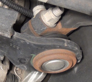
Once two tie rod ends and the sleeve are assembled, that entire link can be installed either way on most older rear-wheel-drive Chrysler products. From the factory, you don't know if the tie rod end with the normal thread is the inner one or the outer one. The only issue with that is you don't know right away which way to turn the sleeve when you need to adjust toe on that wheel, until you try it. You can't switch them on most older Fords because the inner and outer ends have seriously-different lengths, and they have bends in them for clearance from other parts. The link can also be switched on GM cars and light trucks, but on all of these vehicles it is customary to make the normal-threaded end the outer one. One way to tell the ends apart on GM vehicles is by the location of the grease fittings. One comes out the bottom of the housing and one comes out the end of it. If the entire assembly is turned around, it is possible one of the grease fittings could hit the control arm as it moves left and right. Typically that causes the grease fitting to be knocked off, and nothing more.

No torque spec is listed for the castle nuts on the tie rod ends, so again, rely on common sense. These are smaller nuts than those for the ball joints, so expect their torque spec to be a lot lower. It's irrelevant anyway on most models because the nuts are on the back side of the center link where you can't get a socket on the inner ones, so you can't use a torque wrench without a hard-to-find special adapter. Even getting a box wrench on them can be difficult. Expect these nuts to take around 20 †30 foot †pounds, which is easy to achieve with an open-end wrench, then, as before, tighten them just enough more so you can get the cotter pins in.

There's one last thing we have to watch out for related to a pair of tie rod ends. When the linkage is installed and the clamp bolts are tight, if you grab the sleeve and try to rotate it, you'll see the tie rod ends can swivel between the balls and sockets. That freedom to do so is important to allow that movement to take place when the wheels turn left and right, and as the suspension travels up and down. If the two ends are clamped at opposite ends of that travel, the assembly won't be able to swivel. The resulting binding can make it hard to turn fully one way, and repeated twisting of the sleeve can lead to it cracking and breaking. All you need to do to avoid this is to be sure the assembly can be swiveled once the clamp bolts are tight. The alignment specialist is going to check for that when he makes the last two adjustments.

All of the parts up to now must be replaced or must be in good condition for the vehicle to be aligned. They all are responsible for holding a wheel in a certain orientation, either tipped or turned. We're supposed to inspect all of these parts before starting an alignment, and knowing the alignment can't be maintained with a worn part on the vehicle, a conscientious mechanic will not take your money for an alignment or attempt to perform it. It's also proper etiquette to inform the specialist of the new parts you installed and any other services you performed. He is still going to inspect your work so he feels confident when putting his name on the repair order. By double-checking your work, you will also have the confidence to trust the final product.

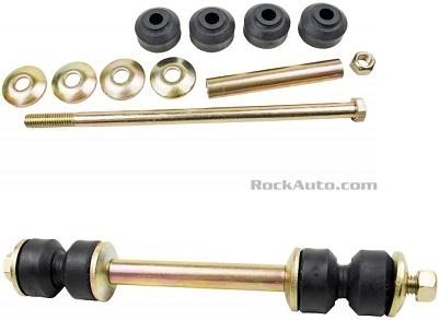
Outer Anti-sway Bar Links

These are of a real common design found on various models from every manufacturer. They fail in two ways. One is when the bolt rusts apart in the middle. Most often that occurs right near the end of the sleeve in the middle of the assembly. The truck body will tip more than usual when cornering at high speeds, and there may be a banging or crunching noise if the two parts hit against each other.

The second failure is when the rubber bushings dry-rot and split apart, then fall off. You'll hear the classic rattling "tambourine" sound when driving over bumpy roads. That's from the washers on the link. Other than slightly reduced cornering comfort, these broken links do not cause a safety hazard. They do not have to be replaced for the truck to be aligned.

Removing the links is harder than it looks. The sleeve is usually rusted to the bolt, but it has to be slid off. Instead, some people use a torch to cut them off. I use an air-powered cutoff tool to cut off the head of the bolt, and then cut through the nut. When you install a new link, the threaded end can go on top or on the bottom, as long as the threaded end doesn't interfere with and hit other parts.

There's two things to be aware of to help this job go better. The first is when you're replacing both outer links, slide in both bolts with their first two washers, two rubber bushings, and sleeve, then the next washer and bushing. I use a rubber band to stop the bolt from sliding out on one side while I assemble the other side. Now swivel the bar up so both bolts go through the other holes, then install the last bushings, washers, and nuts. As an alternative, you might get away with totally assembling one link with the nut just started, then do the other one. The problem is when you fully install one link and tighten the nut, you won't be able to pull the bar far enough to allow the parts to be assembled on the other side. Even two men pulling on the bar will need two boys to help.

The next hint has to do with how far to tighten the nuts. Some people will tighten them as much as possible, but that crushes the bushings so much that they won't be able to flex as the bar moves around. That will reduce the life of the bushings to almost nothing. Proper procedure is to watch the bushings expand as you tighten the nut. Stop tightening it just when the bushings have expanded to the same diameter as the washers, and no more. This will leave them with just the right amount of flexibility and free movement.

Most older GM trucks and rear-wheel-drive cars also used a threaded stud at the top of the front shock absorbers. They use the same type of bushings and washers. Those are also tightened the same way until the bushing diameter matches that of the washers. When removing the old shock absorbers, unscrewing the nuts can be very frustrating and time-consuming. To make this job easier, if those old shock absorbers are being discarded, with a simple trick, both shock absorbers can be replaced in less than five minutes;... Okay, maybe ten minutes. Use a high-quality six-point deep socket that fits the nut perfectly. Due to normal rust buildup, you'll likely have to tap the socket all the way on. Now attach a long extension, and use it as a handle to bend the nut and stud back and forth until it snaps off. Due to the pressure of the compressed bushings, the nut will pop when the stud breaks. Often it only takes a few bends for the stud to give up and break. If it doesn't want to break, or if you can't bend it both ways far enough due to hitting the brake master cylinder or some other obstruction, just bend the stud as far as possible, then use the impact wrench to spin the nut off. Bending the stud will prevent the unit's shaft from spinning.

Coil Springs

The last thing that is critical for a quality alignment but always overlooked is correct chassis ride height. In the '60s and '70s, all Chrysler cars used easily-adjustable torsion bar springs. GM used a similar design on some of their truck models, but only on the four-wheel-drive models. Two-wheel-drive trucks don't have interfering front half shafts, so they can still use coil springs.

Every tire and alignment shop has a small book that lists every car and light truck model and year, where to take the height measurements, and what they should be. When the vehicle's height has sagged below the specified acceptable range, the only option with coil springs is to replace them. If you need to do that, the shock absorbers and outer anti-sway bar links have to be removed, then GM's procedure involves separating the lower ball joint, then prying the lower control arm down a lot. The bottom of the spring sits in a pocket, so it takes a second person with another pry bar to pull the spring out. You can still expect the spring to be under tension and go flying. This is a dangerous procedure.

My method is a lot easier and safer, but it's rather difficult if you have to do it on the ground. I do it on a hoist along with a special post jack that reaches up about four feet. The shock absorber still has to be removed, but not the anti-sway bar link, or even the wheel and tire. Support the lower control arm between the two pivot bolts. With the vehicle's weight removed, the two pivot bolts can be removed. Lower the jack and the spring will extend with it. By the time the control arm is lowered about four inches, all the spring pressure will be removed. Pull the control arm down with one hand, and lift the spring out with your other hand. It can be helpful to have another person pull out on the bottom of the tire, but you'll only need his help for half a minute.

Clean out the dirt and small rocks in the pocket the bottom of the spring sits in. Those pebbles can cause a slight crunching noise for a little while, but what's more important is the new springs have a special rust-resistant coating. The rocks will scratch that coating, leading to early failure. In fact, it's common to find the lowest loop of the spring cracked off, then the vehicle will drop about an inch. We typically reach up in there to feel for that break, but be careful as the ends by the break are usually sharp and will cut your finger. Also look for rusty springs where this coating has been gone for a long time. Hondas are noted for the springs breaking right in the middle, then one of the sharp ends tears through the inner side wall of the tire.

There is a rubber sound isolator that sits on the top of the coil spring. Those usually keep falling off when you lift the new spring in place. Use string or discarded electrical wire to tie the rubber to the spring. That will prevent it from falling off.

If your alignment specialist knows what he's doing, he is going to measure ride height before agreeing to align your truck. To see why this is so important, look at how the lower control arm is nearly perfectly parallel to the ground, and the upper control arm is angled down a lot toward the upper ball joint. (This puts the upper ball joint's stud at a severe angle relative to the housing, which is what leads to their recurring failure). The spindle and the frame make up the last two parts that form a parallelogram with very specific angles designed in. This suspension system is called the "short-arm / long-arm", (SLA) system. It provides the best possible ride comfort because road shock has to change direction multiple times as it passes through the parts before a little that's left finds its way into the body. The disadvantage is it's heavy, uses a lot of parts, and is expensive, so you don't see it much any more except in larger trucks.

The two control arms travel through very specific arcs as they pivot up and down. For the most part, as the lower arm moves up and down, the ball joint moves left and right very little. The upper control arm, on the other hand, swings through a much different arc. As the truck body moves down, the upper arm swings up, and that ball joint moves outward a real lot. That tips the wheel and tire, and reduces how much the tire slides sideways across the road surface. That tipping greatly reduces tire wear. Other than vehicles that use a solid front axle, only Ford's I-beam suspension system is stronger, but that system, and even worse, their miserable twin I-beam system, give the worst tire wear of all the suspension systems. With the twin I-beam system, that poor tire wear gets much worse as the springs sag. There are special offset ball joints, and inserts with offset tapered holes, to correct these height-related problems, but the proper solution is to replace the springs.

While ride quality is best with this SLA system, tire wear is only best when the parallelogram angles are as designed, and that can only be when ride height is correct. As the springs sag with age, both control arms pivot upward at their ball joint ends. The lower ball joint doesn't move outward very much, but the upper one moves a real lot. That outward tilt of the spindle and wheel, (camber), can be readjusted. Caster and camber are always the first two of the three main angles adjusted. But while camber can be brought back to specs, that doesn't fix the incorrect geometry of the control arms or the arcs they go through. Even though all the numbers on the alignment computer look perfect, there will definitely be accelerated tire wear when the springs are sagged.

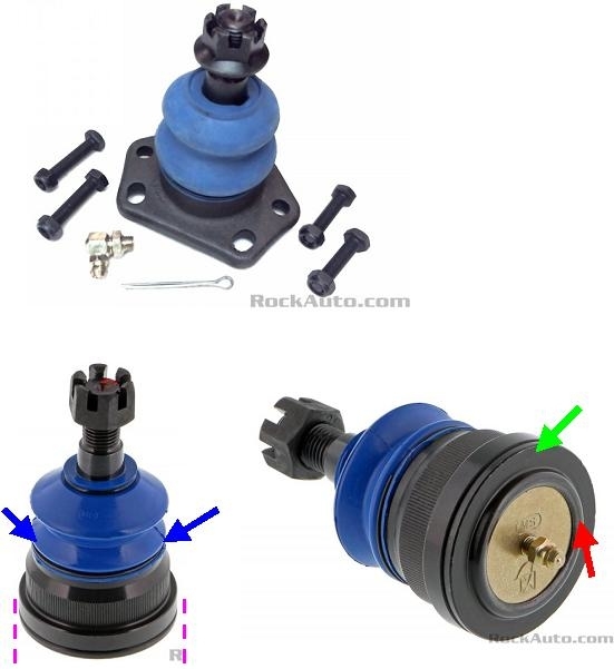
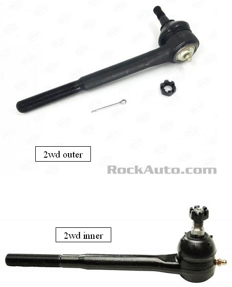
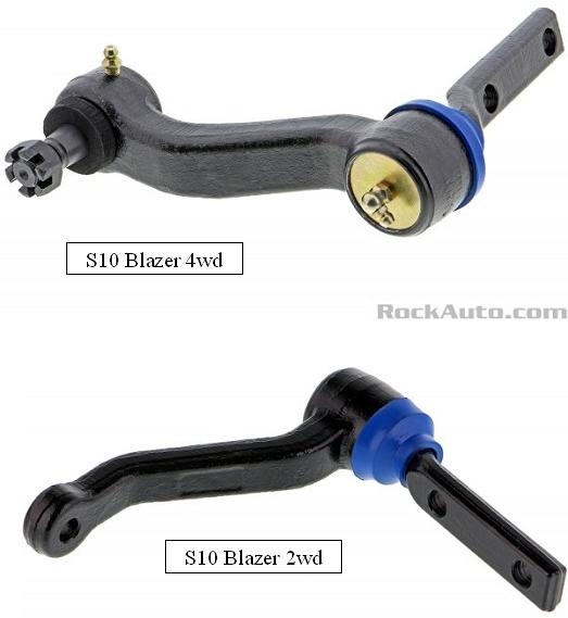
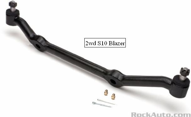
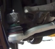
These photos show the parts for your model. In the first one, note the different placement of the grease fittings between the inner and outer tie rod ends. The second one shows the anti-sway bar outer link. In the third photo, you can see the idler arms are different for the two-wheel-drive and the four-wheel-drive models. For your two-wheel-drive model, you only have to look for wear at the swivel joint under the blue boot. When pushing the end of the center link up and down, there should be very little movement. In this application, the ball and socket is on the end of the center link. Note the deep offset of the mounting bar just above the dust boot. On some models that bar can be spun around and be bolted to the frame that way, but that is not correct. The bar should follow the curve at the bottom of the frame rail. The last photo shows the center link for the two-wheel-drive model. There was no listing for the four-wheel-drive, but it won't have the ball and socket on the idler arm end.

For my final note of value, a squeak can be caused on this model by the coil spring rubbing on the pocket in the lower control arm and / or up on top. Some trucks didn't come with the rubber isolator on top. There was a service bulletin that stated those isolators were to be installed above and below each spring to stop that noise, (four spacers per truck).
Was this
answer
helpful?
Yes
No
Friday, November 22nd, 2019 AT 4:13 PM
Tiny
ROB 1503
  • MEMBER
  • 63 POSTS
Wow thank you so very very much. I honestly don't know how you managed to type all this. I am so glad there is still people today that are willing to help others. I don't know how I can ever repay you for having you go thru this. Thank so very much. About my friend, I told her about you guys and she said she's going to check it out since she's actually wanting to be more involved in fixing her own truck.
Was this
answer
helpful?
Yes
No
Sunday, November 24th, 2019 AT 7:25 AM
Tiny
CARADIODOC
  • MECHANIC
  • 33,752 POSTS
Dandy. You may share that in nine years teaching this in a community college, three of my top students were girls, and the guys had a lot of respect for them.
Was this
answer
helpful?
Yes
No
Sunday, November 24th, 2019 AT 6:00 PM
Tiny
ROB 1503
  • MEMBER
  • 63 POSTS
So would i. I have great respect and love it when girls prove to those who are a more closed minded and show them that girls can learn to work on cars and fix it themselves. In all honesty my mentality is that "We Are All Created Equal" and anything a guy can do so can a girl. Plus I hate it when mechanics take advantage of people that don't have that much knowledge about how to fix there cars and over Chaffee them not by a little but by a lot. It's why I've been helping her with what I can after 2 different shops over charged her. 1. Front and rear break replacement came out to be $800.00 and another shop charged her $380.00 for valve cover gasket and they over tightened one side that it began leaking 3 days later. Luckily I was able to get them to refund her most of the money and I did it and showed her how to do it and to my surprise that's when she told me if I could teach her and help her work on her truck. Which actually feels good to help others out of the goodness of your heart that to take advantage of them all for a piece of paper (money) So thank you for helping me, help her.
Was this
answer
helpful?
Yes
No
Sunday, November 24th, 2019 AT 11:30 PM
Tiny
CARADIODOC
  • MECHANIC
  • 33,752 POSTS
That's why we're here too, but I do have to take issue with you one one point. We aren't created equal. I believe we have equal opportunity, although a lot of people never have those opportunities pointed out to them, or explained how to achieve them, then they don't believe those opportunities exist.

If we were created equal, as Abe Lincoln incorrectly said, I would be able to play the violin, as my cousin does professionally, and I'd be able to sing and dance. I have no talent for anything musical. My friends and neighbors appreciate it when I don't sing.

Here's a list of repair articles you can share:

https://www.2carpros.com/articles

Suspension and alignment, Electrical, and Brakes are my specialty areas, and I did teach engine repair too, so I can help with most things related to those areas.
Was this
answer
helpful?
Yes
No
Monday, November 25th, 2019 AT 3:05 PM
Tiny
ROB 1503
  • MEMBER
  • 63 POSTS
You got a point there. I guess what I'm trying to say no one is inferior than the other.

Thank you for sharing the articles. I will check them out and share it with others as well.
Was this
answer
helpful?
Yes
No
Tuesday, November 26th, 2019 AT 12:13 AM
Tiny
STEVE W.
  • MECHANIC
  • 13,002 POSTS
Doc is a great teacher.
I skimmed through what he wrote and would add a few things, GM used some parts on the Blazers that wear out much faster than they really should because they are sort of light duty for the actual vehicle. Having owned at least one of every version from 84 until 2002 and really liking the vehicles, well other than the 2.8 V6 which was almost as powerful as a Chihuahua, there are a few flaws. The ball joints wear out fast, I've seen OEM ones that went less than 40K. GM even changed the spec. On checking them for wear because of this, they allowed more wear as acceptable because they were replacing a lot of them. The idler arms are another issue, although they hold up much better on the 2WD if they are greased.
Repack the front bearings at least at every brake replacement, and watch the front calipers for sticking pins.
Check the rear brakes for stuck adjusters, these do not adjust real well so the adjusters stick and you end up with poor rear brakes.
Interior wise, if it has the rocker style headlight switch and the wheel dash lamp dimmer they tend to get hot and fail because the connectors on the back of the dimmer melt. Watch the door hinge pins as well. Heavy door light pins and bushings are not a good combo.

Don't expect great gas mileage from them as they are a brick going through the air.
Was this
answer
helpful?
Yes
No
Friday, November 29th, 2019 AT 6:35 AM
Tiny
ROB 1503
  • MEMBER
  • 63 POSTS
Steve, thank you for all that extra info. Yea I've noticed a lot of the things you mentioned. I already pointed out some of those things to my friend and surprisingly she got excited. Right away she asked when could we get started. Not the reaction I was expecting. So I guess I might be asking for some more advise for this vehicle, and yes I did notice the gas consumption and also smelled it. Smells like it's running too rich. Already saw a few vacuum hoses disconnected or cracked. Well hopefully I can start working on it soon once the rain clears out. Again thank you both for the useful info and for taking the time to help me out.
Was this
answer
helpful?
Yes
No
Friday, November 29th, 2019 AT 7:04 AM

Please login or register to post a reply.

Sponsored links