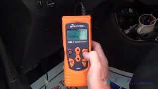
With today's vehicles, a scanner is worth its weight in gold. LOL
I don't know if you want to, but here is an easy test to confirm the sensor is bad:
https://www.2carpros.com/articles/abs-wheel-speed-sensor-test
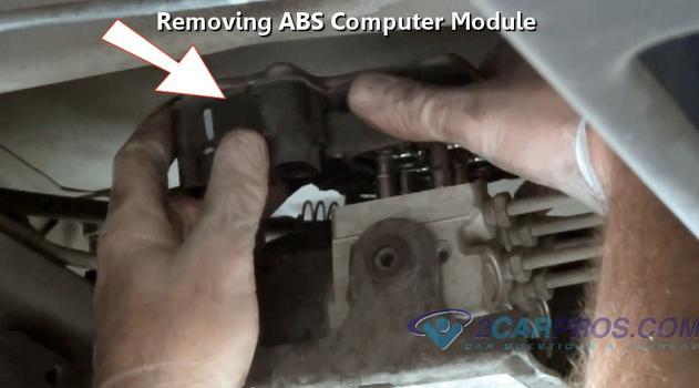
Also, here is a link that shows in general how one is replaced:
https://www.2carpros.com/articles/how-to-replace-an-abs-wheel-speed-sensor
One last thing. I don't know if you need them, but here are the directions specific to your vehicle for replacing both front right and left sensors. I would only replace the bad one in this case, but that's up to you. The attached pictures correlate with the directions.
__________________________________________________________
2007 Toyota Truck Tundra 4WD V8-5.7L (3UR-FE)
Front Speed Sensor
Vehicle Sensors and Switches Sensors and Switches - Brakes and Traction Control Wheel Speed Sensor Service and Repair Removal and Replacement Front Speed Sensor
FRONT SPEED SENSOR
REMOVAL
1. DISCONNECT CABLE FROM NEGATIVE BATTERY TERMINAL
NOTE:
- After the ignition switch is turned OFF, the navigation system requires approximately 90 seconds to record various types of memory and settings. As a result, after turning the ignition switch OFF, wait 90 seconds or more before disconnecting the cable from the negative (-) battery terminal.
- Some systems need to be initialized after the cable is reconnected.
2. REMOVE FRONT WHEEL
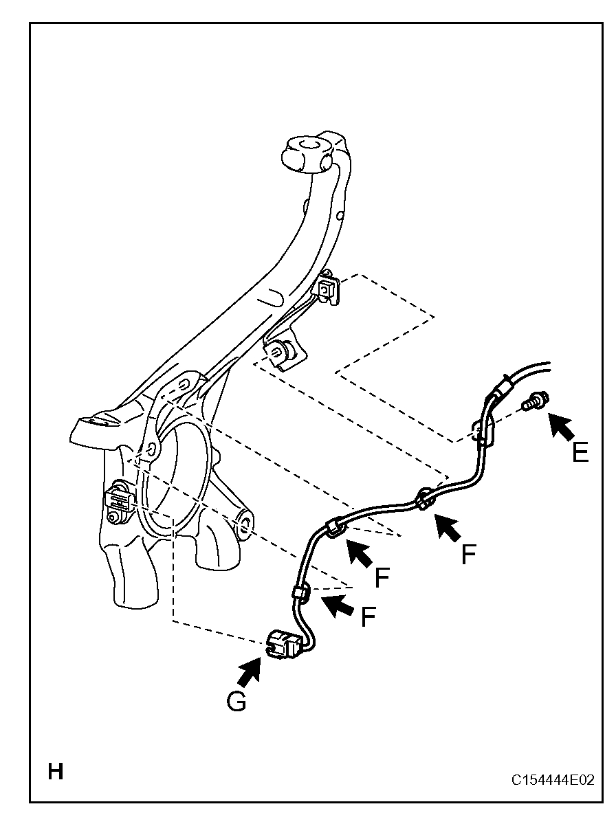
3. REMOVE FRONT SKID CONTROL SENSOR WIRE LH
a. Disconnect the connector (labeled A) from the front speed sensor.
pic 1
b. Detach the 3 clips (labeled B) and remove the clamp bolt (labeled C).
pic 2
c. Disconnect the connector (labeled D).
d. Remove the 3 bolts (labeled E), 3 harness clamps(labeled F) and sensor wire.
4. REMOVE FRONT SPEED SENSOR LH
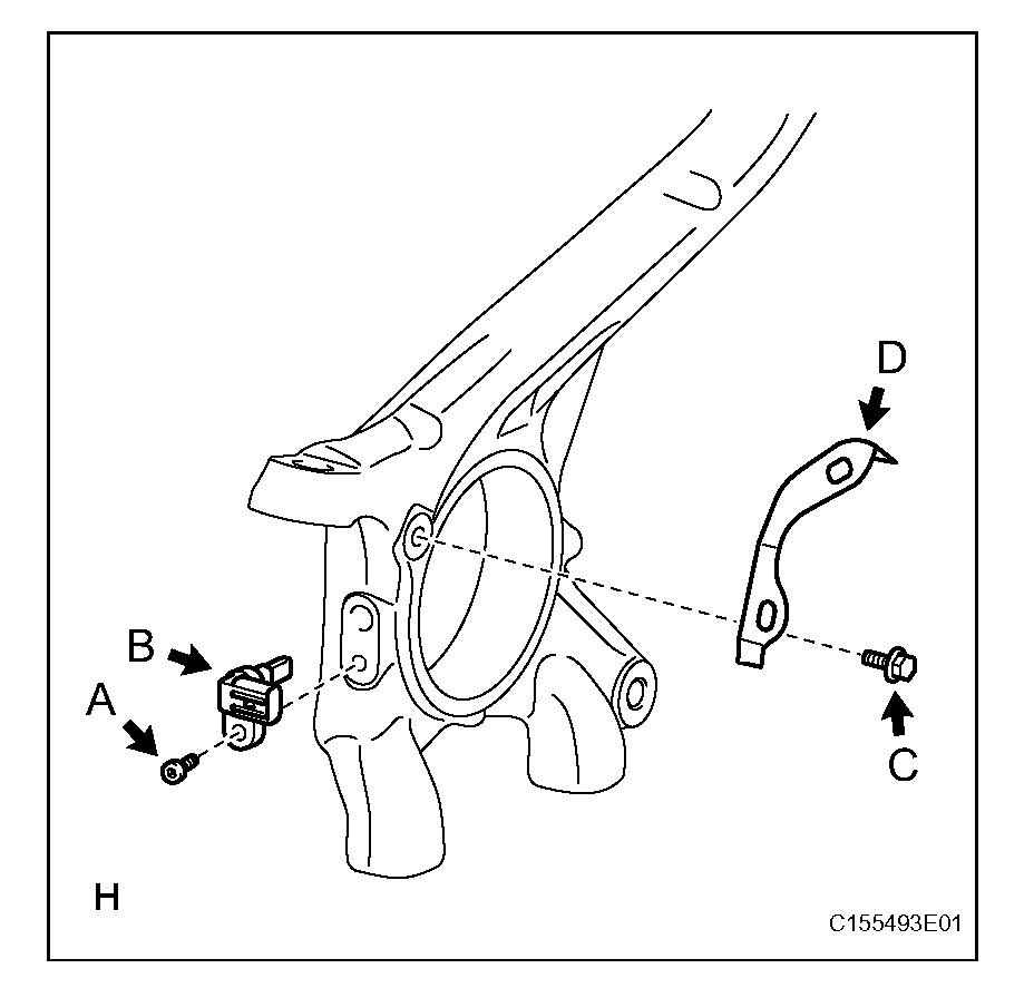
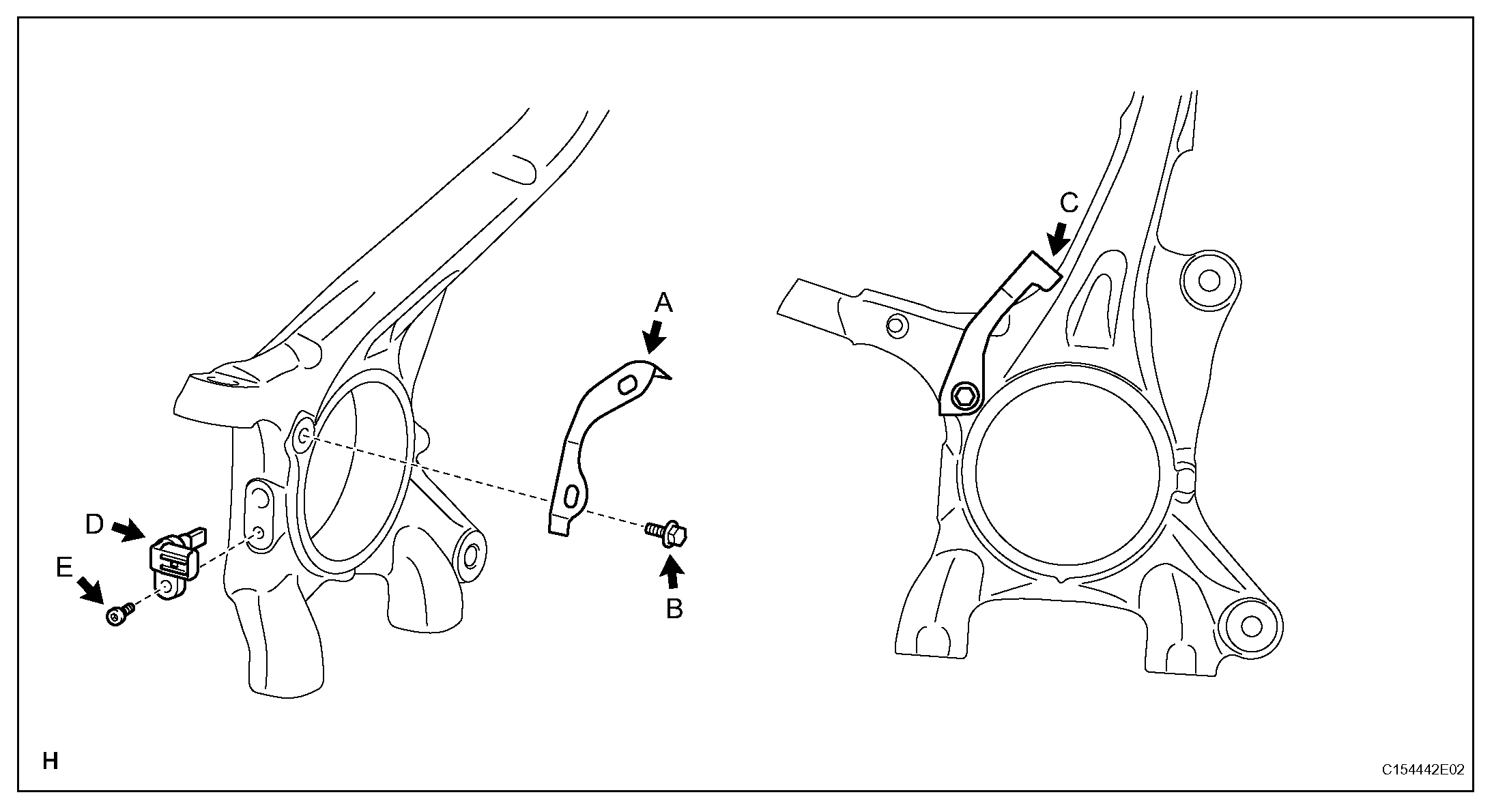
pic 3
a. Remove the hexagon socket head cap bolt (labeled A) and speed sensor (labeled B) from the knuckle.
5. REMOVE FRONT SKID CONTROL SENSOR CLAMP LH
a. Remove the bolt (labeled C) and skid control sensor clamp (labeled D) from the knuckle.
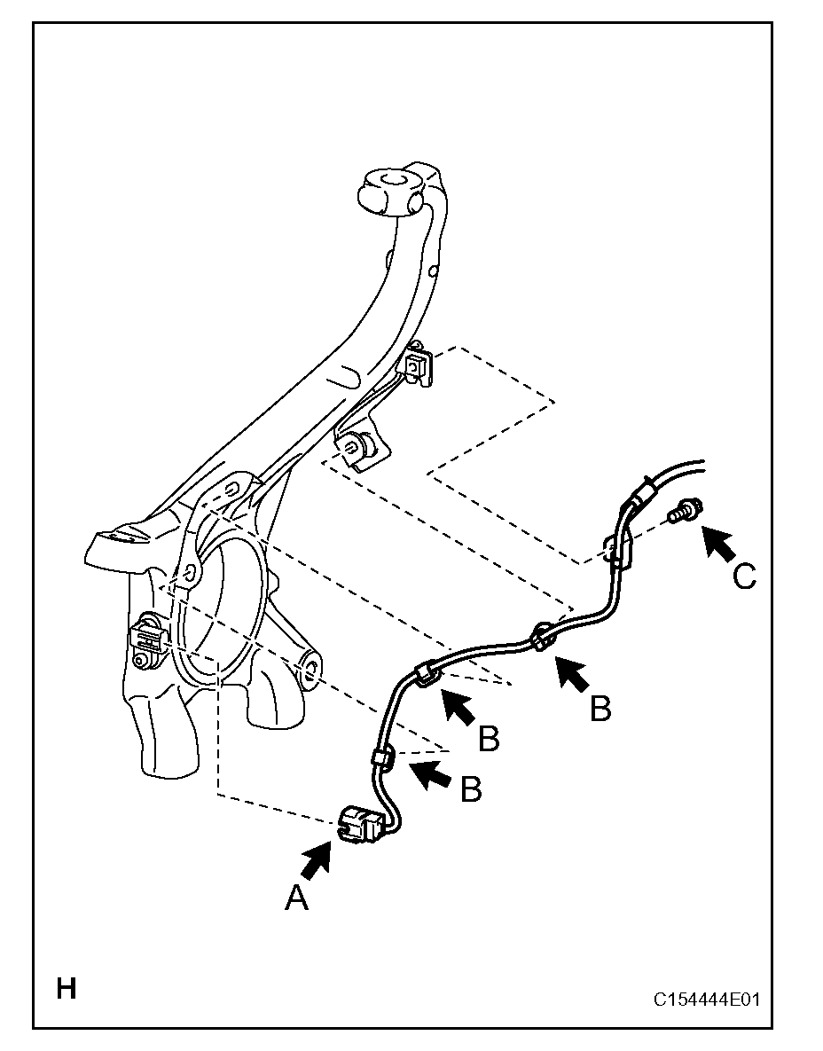
6. REMOVE FRONT SKID CONTROL SENSOR WIRE RH
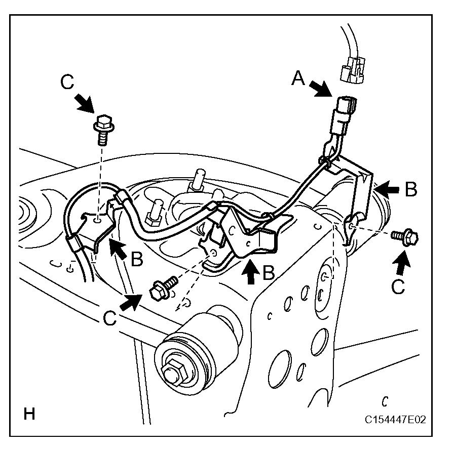
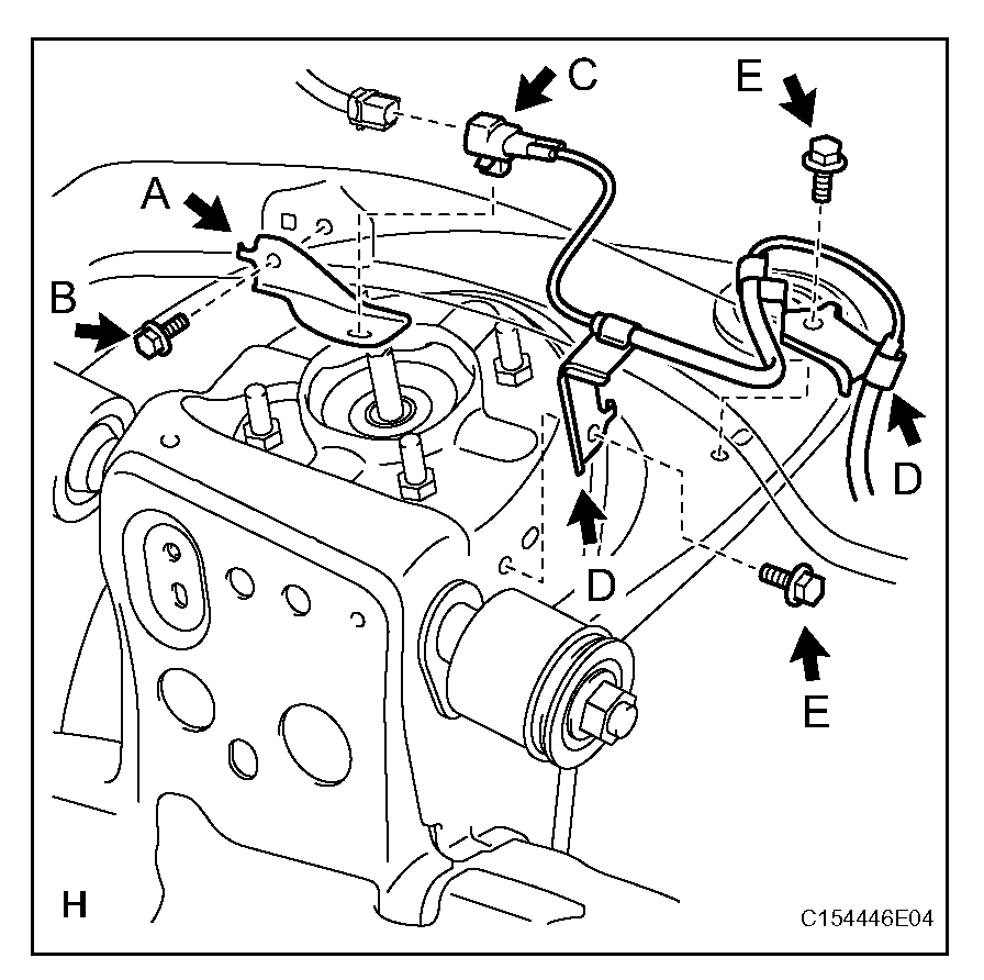
pic 4
a. Disconnect the connector (labeled A) from the front speed sensor.
b. Detach the 3 clips (labeled B) and remove the clamp bolt (labeled C).
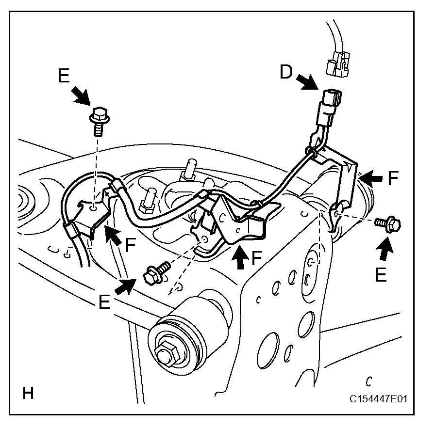
pic 5
c. Disconnect the connector (labeled D).
d. Remove the connector (labeled D) from the skid control sensor clamp (labeled H).
e. Remove the 2 bolts (labeled E) and 2 harness clamps (labeled F).
f. Remove the bolt (labeled G) and skid control sensor clamp (labeled H).
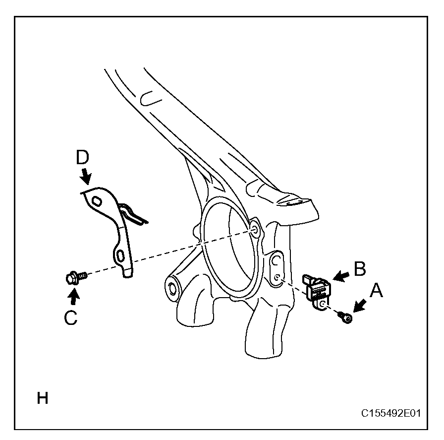
7. REMOVE FRONT SPEED SENSOR RH
pic 6
a. Remove the hexagon socket head cap bolt (labeled A) and speed sensor (labeled B) from the knuckle.
8. REMOVE FRONT SKID CONTROL SENSOR CLAMP RH
a. Remove the bolt (labeled C) and skid control sensor clamp (labeled D) from the knuckle.
INSTALLATION
1. INSTALL FRONT SKID CONTROL SENSOR CLAMP LH
pic 7
a. Install the skid control sensor clamp (labeled A) with the bolt (labeled B).
Torque: 13 N.m (127 kgf. cm, 9 ft.lbf)
NOTE: Install the bracket so that the rotation stopper (labeled C) touches the knuckle.
2. INSTALL FRONT SPEED SENSOR LH
a. Install the speed sensor (labeled D) with the hexagon socket head cap bolt (labeled E).
Torque: 11 N.m (107 kgf. cm, 8 ft.lbf)
NOTE:
- Make sure there are no pieces of iron or other foreign matter attached to the sensor tip part.
- While inserting the speed sensor into the knuckle hole, do not strike or damage the sensor tip part.
- After installing the speed sensor, make sure there is no clearance or foreign matter between the sensor stay part and the knuckle.
- Make sure there is no foreign matter attached to the magnetic rotor.
3. INSTALL FRONT SKID CONTROL SENSOR WIRE LH
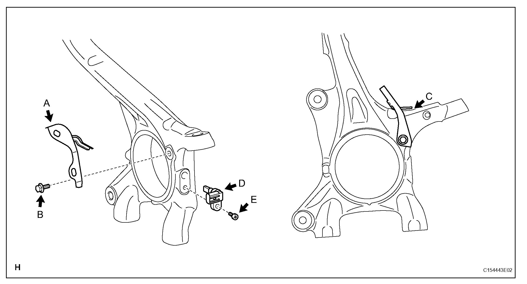
pic 8
a. Connect the connector (labeled A).
b. Install the 3 harness clamps (labeled B) with the 3 bolts (labeled C).
Torque: 13 N.m (127 kgf. cm, 9 ft.lbf)
NOTE:
- When installing the clamps, do not twist the wire harness.
- For clamps with rotation stoppers, make sure the rotation stopper touches the installation position.
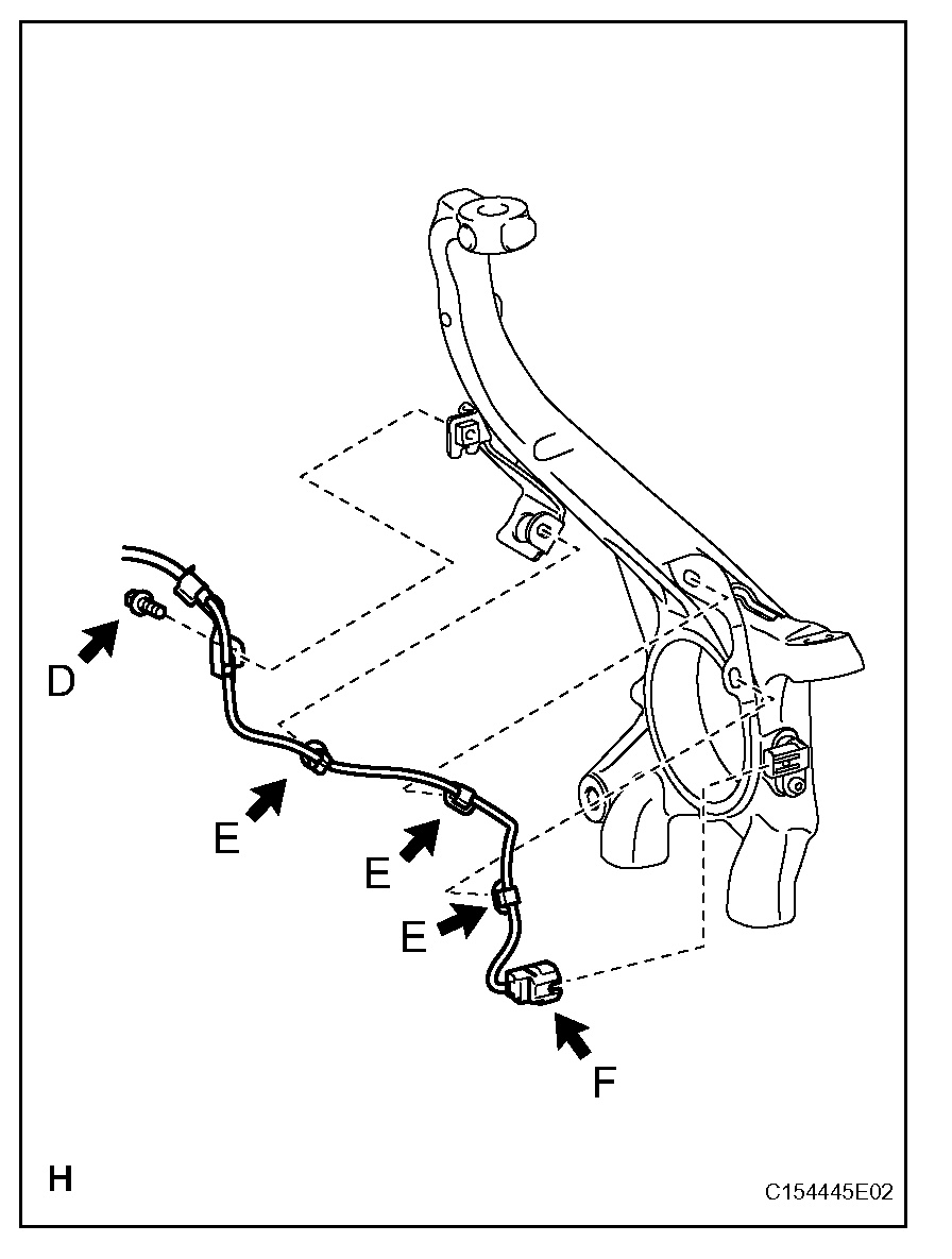
pic 9
c. Install the harness clamp with the bolt (labeled D).
Torque: 13 N.m (127 kgf. cm, 9 ft.lbf)
NOTE:
- When installing the clamp, do not twist the wire harness.
- Make sure the clamp's rotation stopper touches the installation position.
d. Attach the 3 clips (labeled E).
NOTE:
- When installing the clips, do not twist the wire harness.
- When installing the clips, securely insert them as shown in the illustration.
e. Connect the speed sensor connector (labeled F).
NOTE: Securely connect the connector.
4. INSTALL FRONT SKID CONTROL SENSOR CLAMP RH
pic 10
a. Install the skid control sensor clamp (labeled A) with the bolt (labeled B).
Torque: 13 N.m (127 kgf. cm, 9 ft.lbf)
NOTE: Install the bracket so that the rotation stopper(labeled C) touches the knuckle.
5. INSTALL FRONT SPEED SENSOR RH
a. Install the speed sensor (labeled D) with the hexagon socket head cap bolt (labeled E).
Torque: 11 N.m (107 kgf.cm, 8 ft.lbf)
NOTE:
- Make sure there are no pieces of iron or other foreign matter attached to the sensor tip part.
- While inserting the speed sensor into the knuckle hole, do not strike or damage the sensor tip part.
- After installing the speed sensor, make sure there is no clearance or foreign matter between the sensor stay part and the knuckle.
- Make sure there is no foreign matter attached to the magnetic rotor.
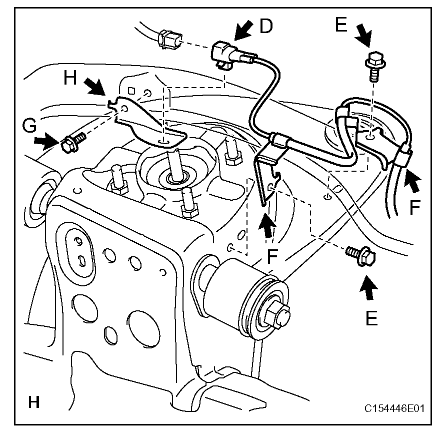
6. INSTALL FRONT SKID CONTROL SENSOR WIRE RH
pic 11
a. Install the skid control sensor clamp (labeled A) with the bolt (labeled B).
Torque: for Bolt B 5.0 N.m (51 kgf. cm, 44 in.lbf)
b. Install the connector (labeled C) with connect the connector (labeled C).
c. Install the 2 harness clamps (labeled D) with the 2 bolts (labeled E).
Torque: for Bolt E 13 N.m (127 kgf.cm, 9 ft.lbf)
NOTE:
- When installing the clamps, do not twist the wire harness.
- For clamps with rotation stoppers, make sure the rotation stopper touches the installation position.
pic 12
d. Install the harness clamp with the bolt (labeled E).
Torque: 13 N.m (127 kgf.cm, 9 ft.lbf)
NOTE:
- When installing the clamp, do not twist the wire harness.
- Make sure the clamp's rotation stopper touches the installation position.
e. Attach the 3 clips (labeled F).
NOTE:
- When installing the clips, do not twist the wire harness.
- When installing the clips, securely insert them as shown in the illustration.
f. Connect the speed sensor connector (labeled G).
NOTE: Securely connect the connector.
7. INSTALL FRONT WHEEL
Torque: for Aluminum Wheel 131 N.m (1336 kgf. cm, 97 ft.lbf)
for Steel Wheel 209 N.m (2131 kgf.cm, 154 ft.lbf)
8. CONNECT CABLE TO NEGATIVE BATTERY TERMINAL
NOTE: Some systems need to be initialized after the cable is reconnected.
9. CHECK SPEED SENSOR SIGNAL
a. Check the speed sensor signal.
___________________________________
If you get a chance, let me know how this works out for you. Also, have a great new year!!!
Joe
Images (Click to make bigger)
Saturday, December 28th, 2019 AT 7:27 PM