Hi and thanks for using 2carpros.com
Both of the codes indicate an issue with the right rear wheel speed sensor. If it has failed, it can actuate the traction control system. This, as a result, will limit engine power to eliminate stability issues.
Have you checked the speed sensor?
I have attached diagnostic flow charts in picture form for you to follow. You can do this or simply replace the sensor to see if the problem is eliminated.
Note: The replacement of the rear sensors is different based on if the vehicle has rear drum or disc brakes.
Circuit Description
The speed sensor used on this vehicle is a multiple pole magnetic pickup. This sensor produces an AC signal that the EBCM uses the frequency from to calculate the wheel speed.
Conditions for Running the DTC
The ignition is ON.
Conditions for Setting the DTC
Either of the following conditions are present for greater than 0.02 seconds.
Either wheel speed sensor circuit is open or shorted.
The wheel speed sensor is open.
Action Taken When the DTC Sets
The ABS/TCS disables.
The ABS/TCS indicator(s) turn on.
Conditions for Clearing the DTC
The condition responsible for setting the DTC no longer exists and the scan tool Clear DTCs function is used.
100 ignition cycles pass with no DTC(s) detected.
Diagnostic Aids
It is very important that a thorough inspection of the wiring and connectors be performed. Failure to carefully and fully inspect wiring and connectors may result in misdiagnosis, causing part replacement with reappearance of the malfunction.
Thoroughly inspect any circuitry that may be causing the complaint for the following conditions:
- Backed out terminals
- Improper mating
- Improperly formed or damaged terminals
- Poor terminal-to-wiring connections
- Physical damage to the wiring harness
The following conditions may cause an intermittent malfunction:
- A poor connection
- Rubbed-through wire insulation
- A broken wire inside the insulation
If the customer's comments reflect that the ABS/TCS indicator is on only during moist environmental conditions (rain, snow, vehicle wash), inspect all the wheel speed sensor circuitry for signs of water intrusion. If the DTC is not current, clear all DTCs and simulate the effects of water intrusion by using the following procedure:
1. Spray the suspected area with a five percent saltwater solution. (Add two teaspoons of salt to twelve ounces of water to make a five percent saltwater solution.)
2. Test drive the vehicle over various road surfaces (bumps, turns, etc.) above 40 km/h (25 mph) for at least 30 seconds.
3. If the DTC returns, replace the suspected WSS or WSS harness.
4. Rinse the area thoroughly when completed.
If an intermittent malfunction exists refer to Testing for Intermittent and Poor Connections for further diagnosis.
Rear Wheel Speed Sensor Resistance
The following table contains resistance values for the front wheel speed sensors at varying sensor temperatures for use in diagnosis. The values are approximate and can be used as a guideline for diagnosis.
Test Description
The number below refers to the step number on the diagnostic table.
2. This step tests the wheel speed sensor and the wheel speed sensor signal circuits for an open.
3. This step tests the wheel speed sensor and the wheel speed sensor signal circuits for a short to ground.
4. This step tests the wheel speed sensor and the wheel speed sensor signal circuits for a short to voltage.
5. This step tests the wheel speed sensor for the proper resistance value.
_________________________
Picture 3 shows the resistance values for the sensor.
Here are a few links that you may find helpful. They show in general how to check a speed sensor, how to use the tools needed, and how to check wiring.
https://www.2carpros.com/articles/abs-wheel-speed-sensor-test
https://www.2carpros.com/articles/abs-wheel-speed-sensor-test
https://www.2carpros.com/articles/how-to-check-wiring
https://www.2carpros.com/articles/how-to-use-a-voltmeter
https://www.2carpros.com/articles/how-to-use-a-test-light-circuit-tester
IF you find the sensor is bad, here are directions specific to your vehicle for replacement. I will start with the rear brakes because that is where I feel the problem is.
REAR
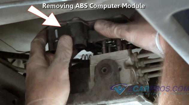
Removal Procedure
See Pic 4
Important: The rear wheel speed sensors and rings are integral with the hub and bearing assemblies.
If a speed sensor or a ring needs replacement, replace the entire hub and bearing assembly. Refer to Wheel Bearing/Hub Replacement - Rear (Domestic) or Wheel Bearing/Hub Replacement - Rear (Export).
1. Raise and support the vehicle on a suitable hoist. Refer to Vehicle Lifting.
2. Remove the rear tire and wheel assembly. Refer to Tire and Wheel Removal and Installation.
3. Remove the rear wheel speed sensor electrical connector located next to the rear strut.
See pic 5
4. Remove the hub and bearing assembly (1). Refer to Wheel Bearing/Hub Replacement - Rear (Domestic) or Wheel Bearing/Hub Replacement - Rear (Export).
Installation Procedure
See pic 4
1. Install the hub and bearing assembly (1) to the vehicle. Refer to Wheel Bearing/Hub Replacement - Rear (Domestic) or Wheel Bearing/Hub Replacement - Rear (Export).
See Pic 5
2. Install the rear wheel speed sensor electrical connector.
3. Install the wheel and tire assembly. Refer to Tire and Wheel Removal and Installation.
4. Lower the vehicle.
5. Turn the ignition switch to the RUN position with the engine off.
6. Perform the A Diagnostic System Check - ABS.
______________________________
Front sensor:
FRONT
Removal Procedure
Important: The front wheel speed sensors and rings are integral with the hub and bearing assemblies. If a speed sensor or a ring needs replacement, replace the entire hub and bearing assembly. Do not service the harness pigtail individually because the harness pigtail is part of the sensor, Refer to Wheel Bearing/Hub Replacement - Front.
See Pic 6
1. Raise and support the vehicle on a suitable hoist. Refer to Vehicle Lifting.
2. Remove the front tire and wheel assembly. Refer to Tire and Wheel Removal and Installation.
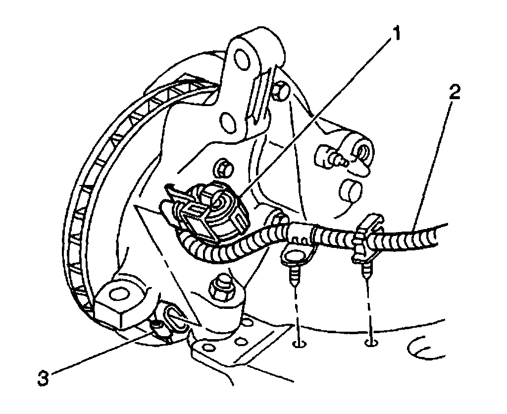
3. Remove the front wheel speed sensor jumper harness electrical connector (1) from the front wheel speed sensor connector (3).
See Pic 7
4. Remove the hub and bearing assembly (2). Refer to Wheel Bearing/Hub Replacement - Front.
Installation Procedure
See Pic 6
1. Install the hub and bearing assembly (2) to the vehicle. Refer to Wheel Bearing/Hub Replacement - Front.
See Pic 7
2. Install the front wheel speed sensor jumper harness electrical connector (1) to front wheel speed sensor connector (3).
3. Install the wheel and tire assembly. Refer to Tire and Wheel Removal and Installation.
4. Lower the vehicle.
5. Turn the ignition switch to the RUN position with the engine off.
6. Perform the A Diagnostic System Check - ABS.
Let me know if this helps or if you have other questions.
Take care,
Joe
Images (Click to make bigger)
SPONSORED LINKS
Friday, January 25th, 2019 AT 8:08 PM