Welcome back:
First, I would start by checking the compression myself to determine it they are correct. If they are, then you need to do what is called a wet compression test. Basically, about a tablespoon of oil into the cylinder to see if the compression increases. If it does, then the problem is the rings. If there is no change, the problem is either a cylinder head gasket a timing issue, or a problem with the valves. Lets start with checking compression both wet and dry. Here are the directions in general showing how to check:
https://www.2carpros.com/articles/how-to-test-engine-compression
Here are the directions specific to your vehicle:
Engine Compression Test
Vehicle Powertrain Management Tune-up and Engine Performance Checks Compression Check Testing and Inspection Component Tests and General Diagnostics Engine Compression Test
ENGINE COMPRESSION TEST
Engine Compression Test
Special Tools
EN-48248 - Cylinder Compression Pressure Gauge
For equivalent regional tools, refer to Special Tools See: Engine > Electrical / Mechanical Repair > Special Tools.
Removal Procedure
1. Remove the throttle body assembly. Refer to Throttle Body Assembly Replacement See: Throttle Body > Removal and Replacement > Throttle Body Assembly Replacement.
2. Remove the spark plugs. Refer to Spark Plug Replacement See: Spark Plug > Removal and Replacement > Spark Plug Replacement.
3. Remove the relay holder cover.
4. Remove the fuel pump relay.
Note: The engine cranking time for the compression test should be less then 10 seconds and at 30 second intervals.
5. Crank the engine with the starter motor for 5 seconds to remove any foreign substances from the cylinders.
6. Prior to taking a compression reading, verify the cranking speed is greater than 300 RPM. If the cranking speed is below 300 RPM, repair the slow cranking speed condition before continuing with the compression test.
7. Install EN-48248 - gauge in the spark plug bore for the cylinder that is being checked.
8. Using the vehicle's starter motor, rotate or crank the engine for 4 compression strokes, puffs, for the cylinder being tested.
9. Observe the compression gauge and note the reading as the compression test is being performed. A normal cylinder reading will be indicated if compression builds up quickly and evenly to the specified level. An abnormal reading will be indicated if compression is low on the first compression stroke, starts increasing on the following compression strokes but does not reach the specified level.
10. Record the compression reading for the cylinder just tested.
11. Repeat steps for all remaining cylinders. All 4 cylinders must be tested to obtain valid test results. Record the readings.
12. The maximum pressure differential should not exceed 100 kPa (14.5 psi).
13. The nominal cylinder compression value is
* for natural aspirated engines 1300 kPa - 1500 kPa (188.5 psi - 217.6 psi).
* for turbo engines 1200 kPa - 1400 kPa (174 psi - 203.1 psi).
Installation Procedure
1. Install the fuel pump relay.
2. Install the relay holder cover.
3. Install the spark plugs. Refer to Spark Plug Replacement See: Spark Plug > Removal and Replacement > Spark Plug Replacement.
4. Install the throttle body assembly. Refer to Throttle Body Assembly Replacement See: Throttle Body > Removal and Replacement > Throttle Body Assembly Replacement.
_______________________________________________
Now, if you find compression low in cylinder 4, add about a tablespoon full of motor oil into cylinder 4 through the spark plug hole. If compression increases, then the problem is related to the piston rings. If it doesn't, then we have to check for a possible blown head gasket. Here is a link that shows how that is done:
https://www.2carpros.com/articles/head-gasket-blown-test
If you find the head gasket isn't an issue, then the cylinder head needs removed so you can inspect the valves for damage. Here are the directions for cylinder head replacement. They are very extensive. Don't even consider this until you have done the aforementioned tests. Also, once you do the tests, I will be better able to give you an idea as to what it may cost to fix.
__________________________________________
CYLINDER HEAD REPLACEMENT
Cylinder Head Replacement All attached pictures correlate with these directions.
Special Tools
EN-470-B - Angular Torque Wrench
EN-953-A - Fixing Tool
EN-955-10 - Fixing Pin from EN-955 - Kit
For equivalent regional tools, refer to Special Tools See: Engine > Electrical / Mechanical Repair > Special Tools.
Removal Procedure
1. Disconnect the battery negative cable. Refer to Battery Negative Cable Disconnection and Connection See: Negative > Removal and Replacement > Battery Negative Cable Disconnection and Connection.
2. Remove the engine sight shield.
3. Remove the air cleaner assembly along with the air cleaner outlet duct. Refer to Air Cleaner Assembly Replacement See: Air Cleaner Housing > Removal and Replacement and Air Cleaner Outlet Duct Replacement See: Air Cleaner Fresh Air Duct/Hose > Removal and Replacement > Air Cleaner Outlet Duct Replacement.
4. Remove the positive crankcase ventilation pipe. Refer to Positive Crankcase Ventilation Hose/Pipe/Tube Replacement See: PCV Valve Hose > Removal and Replacement > Positive Crankcase Ventilation Hose/Pipe/Tube Replacement.
5. Remove the intake manifold. Refer to Intake Manifold Replacement See: Intake Manifold > Removal and Replacement > Intake Manifold Replacement.
6. Remove the turbocharger. Refer to Turbocharger Replacement See: Turbocharger > Removal and Replacement > Turbocharger Replacement.
7. Remove the engine control module wiring harness (1) from camshaft cover:
* Disconnect the intake camshaft position sensor wiring harness plug (7).
* Disconnect the intake camshaft position actuator solenoid valve wiring harness plug (6).
* Disconnect the exhaust camshaft position sensor wiring harness plug (4).
* Disconnect the exhaust camshaft position actuator solenoid valve wiring harness plug (5).
* Disconnect the engine coolant temperature sensor wiring harness plug (3).
8. Place a drain pan underneath the vehicle.
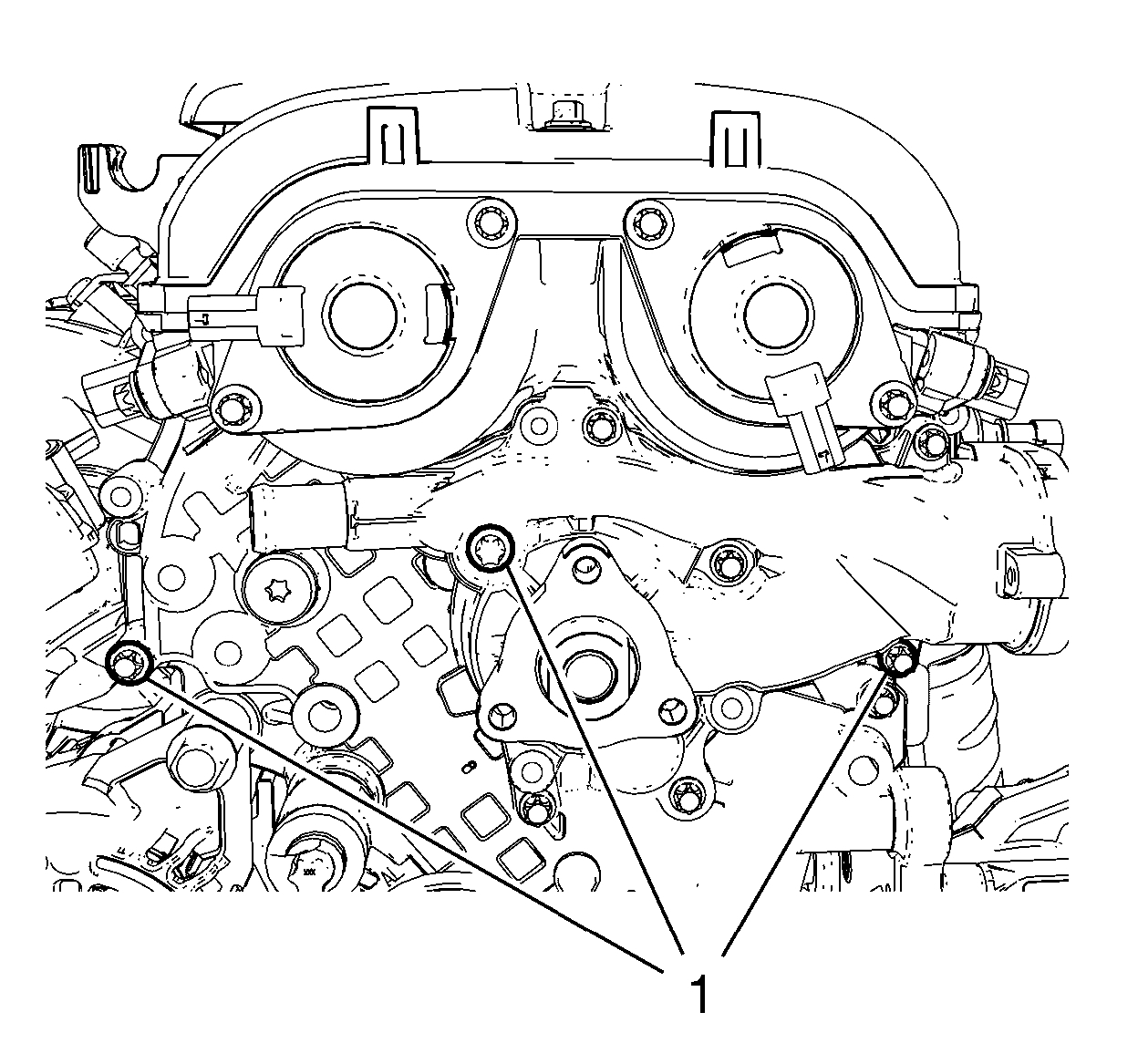
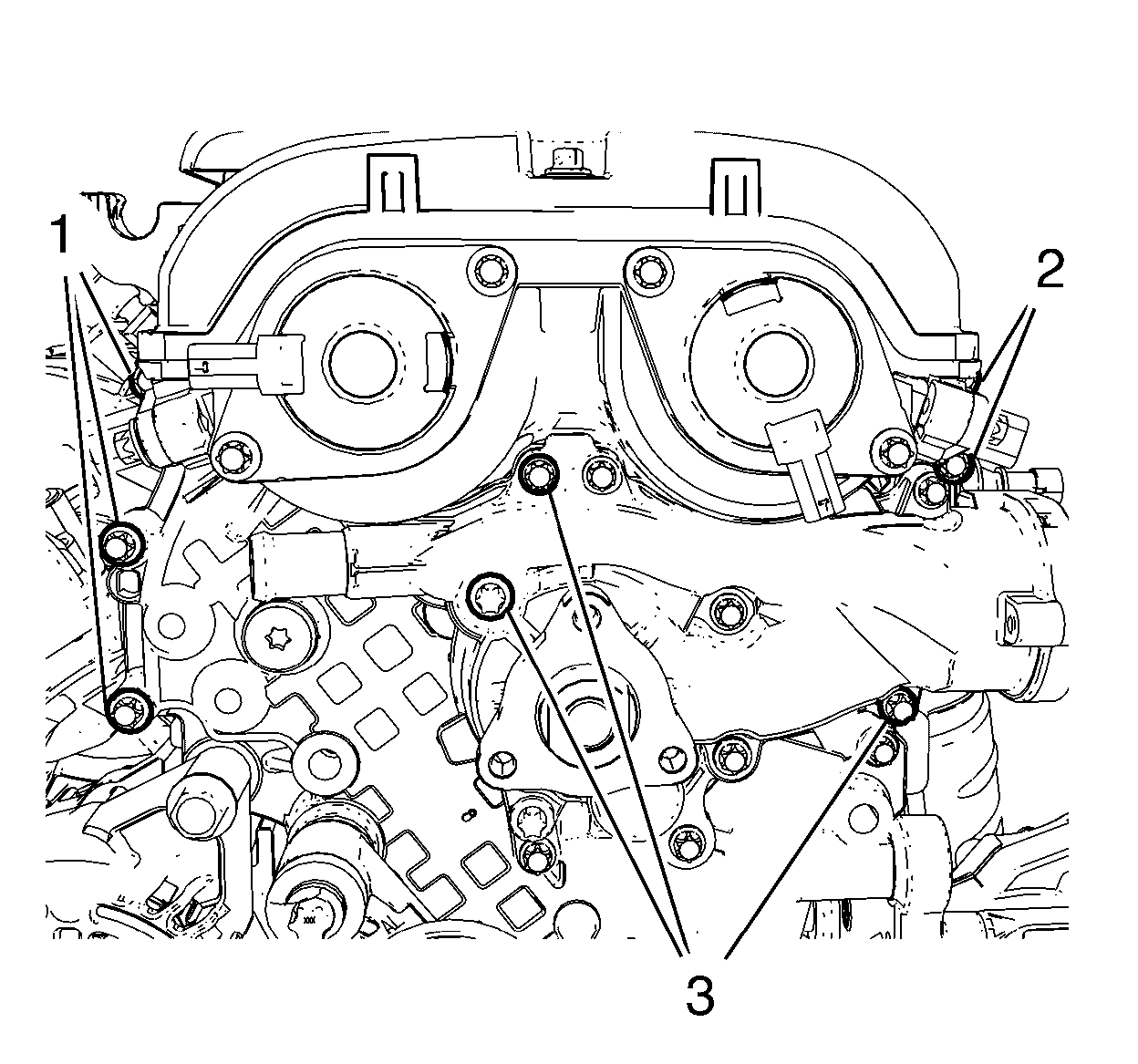
9. Remove the oil cooler inlet hose clamp and the oil cooler inlet hose (1).
10. Remove the radiator inlet hose clamp and the radiator inlet hose (4).
11. Remove the engine coolant air bleed hose (2).
12. Disconnect the engine coolant temperature sensor wiring harness plug (3).
13. Remove the heater inlet hose from the water outlet. Refer to Heater Inlet Hose Replacement (1.8L LUW and LWE) See: Heater Hose > Removal and ReplacementHeater Inlet Hose Replacement (1.4L LUV) See: Heater Hose > Removal and ReplacementHeater Inlet Hose Replacement (2.0L Diesel LUZ) See: Heater Hose > Removal and Replacement.
14. Remove the ground cable bolt (2) and the ground cable (1).
15. Unclip the radiator outlet hose quick connector clamp (2).
16. Remove the radiator outlet hose (3) from the engine coolant thermostat housing (1).
17. Remove the engine mount bracket. Refer to Engine Mount Bracket Replacement - Right Side See: Engine Mount > Removal and Replacement > Engine Mount Bracket Replacement - Right Side.
18. Remove the drive belt. Refer to Drive Belt Replacement See: Drive Belt > Removal and Replacement > Drive Belt Replacement.
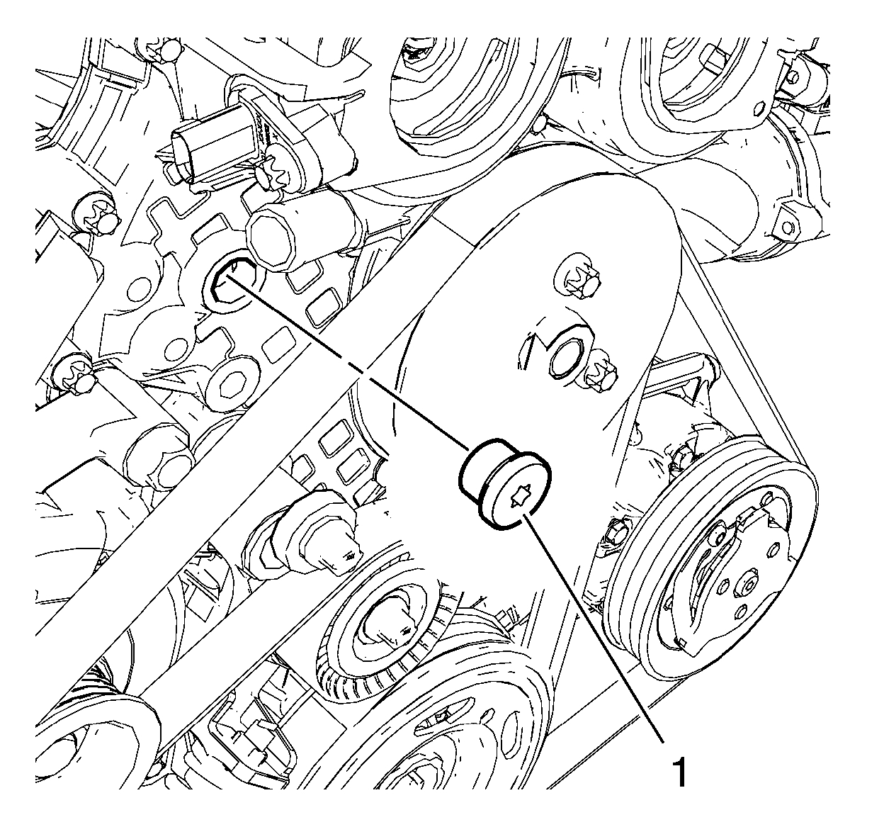
19. Remove the water pump pulley. Refer to Water Pump Pulley Removal See: Engine > Overhaul > Water Pump Pulley Removal.
20. Remove the drain plug (1) and the seal ring (2) and allow the remaining coolant fluid to drain out of the engine block. DISCARD the seal ring.
21. Install the drain plug (1) and a NEW seal ring (2) and tighten the plug to 15 Nm (11 lb ft).
22. Remove 5 engine front cover bolts (1, 2).
23. Remove 3 water pump bolts (3).
24. Install the engine mount bracket. Refer to Engine Mount Bracket Replacement - Right Side See: Engine Mount > Removal and Replacement > Engine Mount Bracket Replacement - Right Side.
25. Install the engine mount. Refer to Engine Mount Replacement - Right Side See: Engine Mount > Removal and Replacement > Engine Mount Replacement - Right Side.
26. Remove the ignition coil. Refer to Ignition Coil Replacement See: Ignition Coil > Removal and Replacement > Ignition Coil Replacement.
27. Remove the camshaft cover. Refer to Camshaft Cover Replacement See: Valve Cover > Removal and Replacement > Camshaft Cover Replacement.
28. Set engine to TDC. Refer to Camshaft Timing Chain Adjustment See: Engine > Overhaul > Camshaft Timing Chain Adjustment.
29. Remove the 2 camshaft position actuator solenoid valves. Refer to Camshaft Position Actuator Solenoid Valve Removal See: Engine > Overhaul > Camshaft Position Actuator Solenoid Valve Removal.
30. Remove the timing chain tensioner plug (1) from the engine front cover.
Note: Remove and reinstall the EN-953-A - fixing tool for this step.
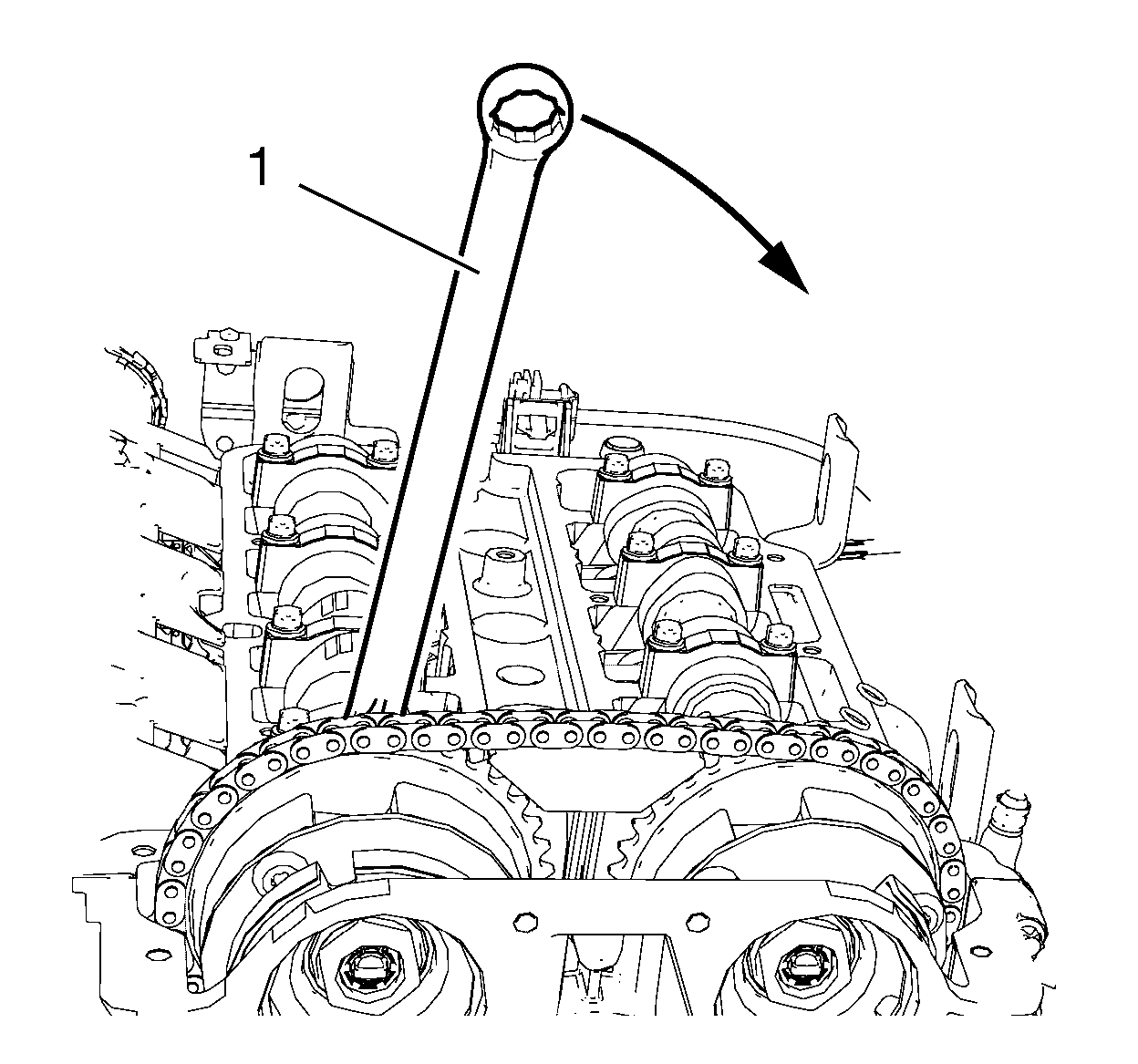
31. Install a wrench (1) to the hexagon of the intake camshaft and rotate it in direction of the arrow to apply tension to the timing chain and hold.
32. Install EN-955-10 - pin (2) to the timing chain tensioner bore (1) to secure it in place.
33. Remove the wrench from the intake camshaft.
34. Remove 2 upper timing chain guide bolts (1).
35. Remove upper timing chain guide (2).
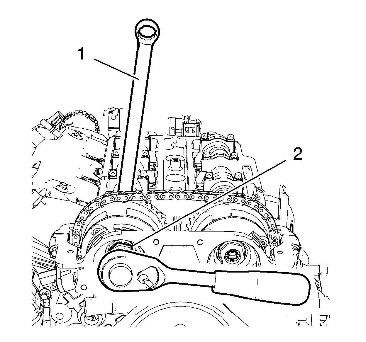
36. Loosen the intake camshaft sprocket bolt (2) while holding the hexagon of intake camshaft sprocket with a wrench (1).
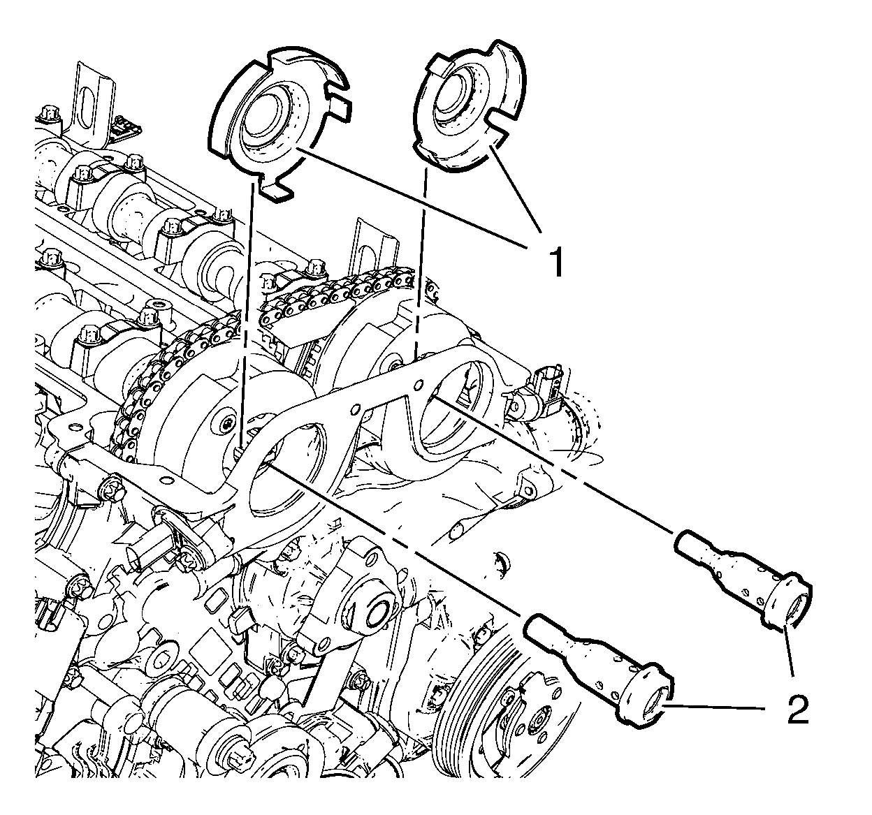
37. Loosen the exhaust camshaft sprocket bolt while holding with a wrench.
38. Remove the 2 camshaft sprocket bolts (2) and the 2 camshaft position exciter wheels (1).
39. Remove the 2 camshaft sprockets (2) along with the timing chain (1) and place it in the engine front cover.
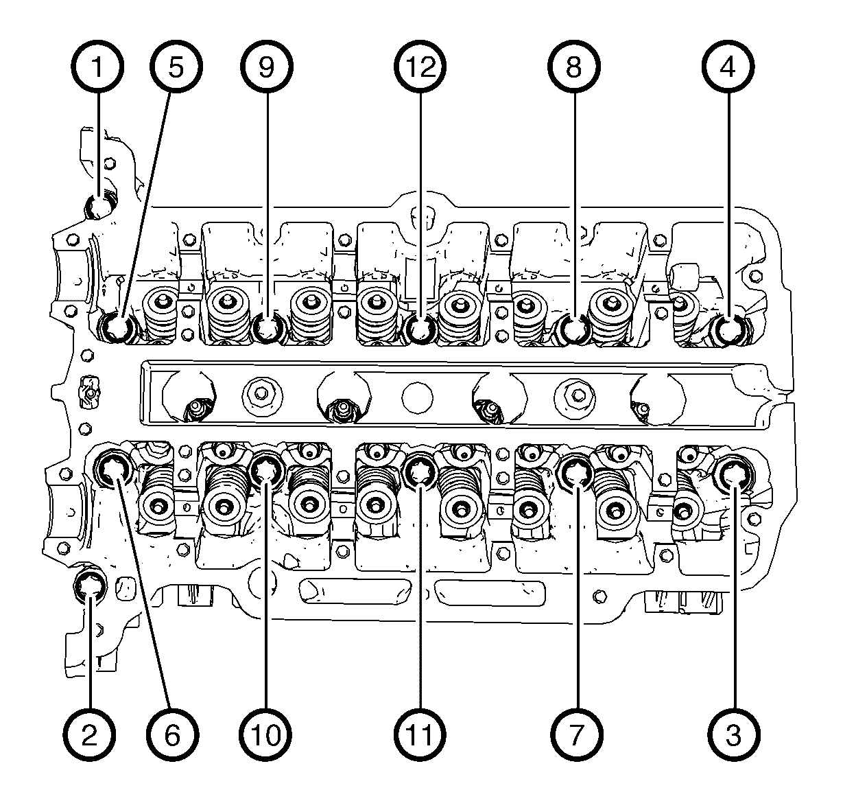
40. Loosen the 12 cylinder head bolts in the sequence as shown. Use the following procedure:
1. Loosen the cylinder head bolts 90 degrees.
2. Loosen the cylinder head bolts 180 degrees.
41. Remove and DISCARD the 12 cylinder head bolts.
42. Move the cylinder head assembly slightly in direction of the transmission.
Note: Mind the timing chain tensioner and the timing chain guide pin.
Note: A second technician is required.
43. Remove the cylinder head assembly.
44. Remove the cylinder head gasket.
45. Remove the assembly parts from cylinder head:
* Remove the EN-953-A - fixing tool.
* Remove the engine coolant thermostat housing. Refer to Engine Coolant Thermostat Housing Removal See: Engine > Overhaul > Engine Coolant Thermostat Housing Removal.
* Remove the water outlet. Refer to Water Outlet Removal See: Engine > Overhaul > Water Outlet Removal.
* Remove the intake camshaft. Refer to Intake Camshaft Removal See: Engine > Overhaul > Intake Camshaft Removal.
* Remove exhaust camshaft. Refer to Exhaust Camshaft Removal See: Engine > Overhaul > Exhaust Camshaft Removal.
* Remove the hydraulic valve lash adjuster arms. Refer to Hydraulic Valve Lash Adjuster Arm Removal See: Engine > Overhaul > Hydraulic Valve Lash Adjuster Arm Removal.
* Remove the hydraulic valve lash adjusters. Refer to Hydraulic Valve Lash Adjuster Removal See: Engine > Overhaul > Hydraulic Valve Lash Adjuster Removal.
* Remove the 3 engine lift brackets.
Installation Procedure
1. Install the cylinder head assembly parts:
* Install the 3 engine lift brackets.
Caution: Refer to Fastener Caution See: Vehicle > Technician Safety Information > Fastener Caution.
* Install the 3 engine lift bracket bolts and tighten to 22 Nm (16 lb ft).
* Install the hydraulic valve lash adjusters. Refer to Hydraulic Valve Lash Adjuster Installation See: Engine > Overhaul > Hydraulic Valve Lash Adjuster Installation.
* Install the hydraulic valve lash adjuster arms. Refer to Hydraulic Valve Lash Adjuster Arm Installation See: Engine > Overhaul > Hydraulic Valve Lash Adjuster Arm Installation.
* Install the exhaust camshaft. Refer to Exhaust Camshaft Installation See: Engine > Overhaul > Exhaust Camshaft Installation.
* Install the intake camshaft. Refer to Intake Camshaft Installation See: Engine > Overhaul > Intake Camshaft Installation.
* Install the water outlet. Refer to Water Outlet Installation See: Engine > Overhaul > Water Outlet Installation.
* Install the engine coolant thermostat housing. Refer to Engine Coolant Thermostat Housing Installation See: Engine > Overhaul > Engine Coolant Thermostat Housing Installation.
Note: Adjust the camshafts using the hexagon and a wrench.
* Install the EN-953-A - fixing tool.
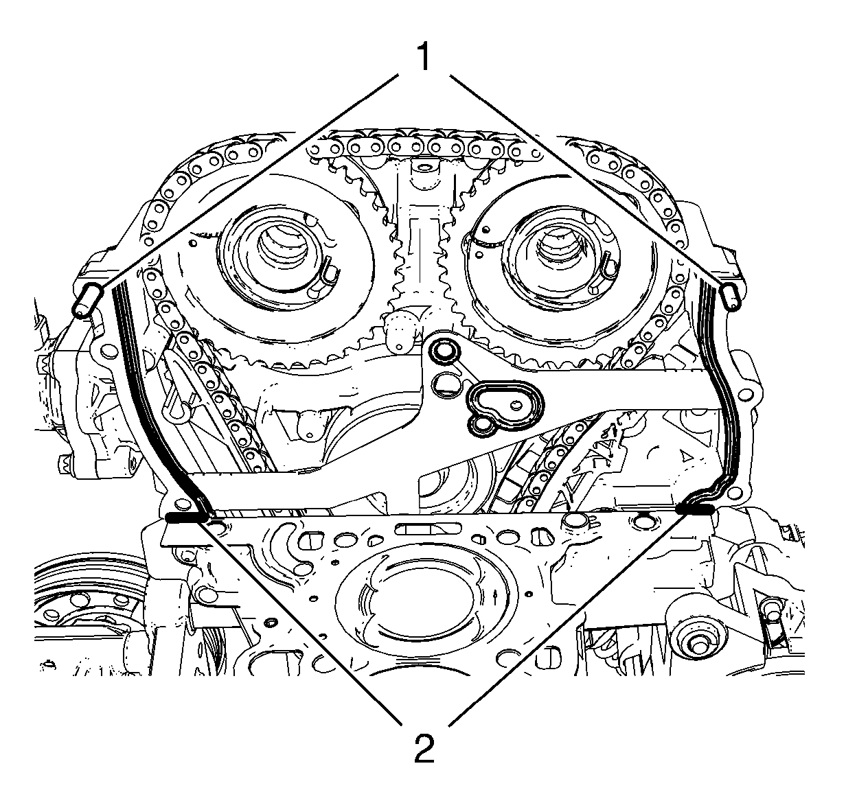
2. Cut the 2 elastomer sealing lips (1) from engine front cover gasket.
3. Bend down the engine front cover gasket at the predetermined breaking points (arrows).
4. Clean sealing surfaces of engine front cover and engine block from grease and old gasket material.
5. Inspect cylinder block and cylinder head for flatness. Refer to Cylinder Head Cleaning and Inspection See: Engine > Overhaul > Cylinder Head Cleaning and Inspection and Engine Block Cleaning and Inspection See: Engine > Overhaul > Engine Block Cleaning and Inspection.
Note: The thickness of the sealing bead should be 2 mm (0.0787 in).
6. Apply sealing compound to the shown areas (1). Refer to Adhesives, Fluids, Lubricants, and Sealers See: Engine > Fluid Types > Adhesives, Fluids, Lubricants, and Sealers.
Note: Mind the marking on the cylinder head gasket for top side.
7. Install the cylinder head gasket to engine block.
8. Install 2 engine front cover bolts (1) in order to guide the NEW upper engine front cover gasket.
9. Install the NEW upper engine front cover gasket.
10. Apply sealing compound to the shown areas (2). The thickness of the sealing bead should be 2 mm (0.0787 in).
Note: A second technician is required. Guide the timing chain guide pin (2) to the timing chain guide and the timing chain tensioner (1) with the installed fixing pin through the timing chain tensioner plug bore in engine front cover.
11. Install the cylinder head (3).
12. Loosely install 12 NEW cylinder head bolts.
13. Adjust the cylinder head to the engine front cover. Use a rubber mallet.
14. Locate the engine front cover to cylinder head by installing 3 bolts (1).
15. Tighten the 3 bolts (1) to 8 Nm (71 lb in).
Caution: Refer to Torque-to-Yield Fastener Caution See: Timing Components > Technician Safety Information > Torque-to-Yield Fastener Caution.
16. Tighten the cylinder head bolts in the sequence as shown and in the following order:
1. Tighten the cylinder head bolts a first pass to 35 Nm (26 lb ft).
2. Tighten the cylinder head bolts a final pass to an additional 180 degrees, using EN-470-B - wrench.
17. Loosen the 3 bolts from engine front cover.
18. Install the 5 remaining bolts to engine front cover and water pump.
19. Tighten the 5 engine front cover bolts (1, 2) to 8 Nm (71 lb in).
20. Tighten the 3 water pump bolts (3) to 8 Nm (71 lb in).
21. Remove the engine mount bracket. Refer to Engine Mount Bracket Replacement - Right Side See: Engine Mount > Removal and Replacement > Engine Mount Bracket Replacement - Right Side.
22. Install the water pump pulley. Refer to Water Pump Pulley Installation See: Engine > Overhaul > Water Pump Pulley Installation.
23. Install the drive belt. Refer to Drive Belt Replacement See: Drive Belt > Removal and Replacement > Drive Belt Replacement.
24. Install engine mount bracket. Refer to Engine Mount Bracket Replacement - Right Side See: Engine Mount > Removal and Replacement > Engine Mount Bracket Replacement - Right Side.
25. Install the engine mount. Refer to Engine Mount Replacement - Right Side See: Engine Mount > Removal and Replacement > Engine Mount Replacement - Right Side.
26. Install the 2 camshaft sprockets (2) along with the timing chain (1).
Note: Camshaft position exciter wheels should stay rotatable.
27. Install the 2 camshaft position exciter wheels (1) and the 2 camshaft sprocket bolts (2).
28. Adjust engine to TDC and tighten the camshaft sprockets and install upper timing chain tensioner guide. Refer to Camshaft Timing Chain Adjustment See: Engine > Overhaul > Camshaft Timing Chain Adjustment.
29. Rotate the crankshaft for 720° and check the engine timing again. Repeat the adjustment procedure if necessary.
30. Remove all special tools for timing chain adjustment. Refer to Camshaft Timing Chain Adjustment See: Engine > Overhaul > Camshaft Timing Chain Adjustment.
31. Install the timing chain tensioner plug and tighten to 35 Nm (26 lb ft).
32. Install the 2 camshaft position actuator solenoid valves. Refer to Camshaft Position Actuator Solenoid Valve Installation See: Engine > Overhaul > Camshaft Position Actuator Solenoid Valve Installation.
33. Install the camshaft cover. Refer to Camshaft Cover Replacement See: Valve Cover > Removal and Replacement > Camshaft Cover Replacement.
34. Install the ignition coil and connect the ignition coil wiring harness plug. Refer to Ignition Coil Replacement See: Ignition Coil > Removal and Replacement > Ignition Coil Replacement.
35. Connect radiator outlet hose (3) to engine coolant thermostat housing (1). Clip quick connector (2).
36. Install the ground cable (1) and the ground cable bolt (2) and tighten to 20 Nm (15 lb ft).
37. Install the radiator inlet hose (4) and the radiator inlet hose clamp to the water outlet.
38. Install the oil cooler inlet hose (1) and the oil cooler inlet hose clamp to the water outlet.
39. Connect the engine coolant air bleed hose (2) to the water outlet.
40. Connect the engine coolant temperature sensor wiring harness plug (3).
41. Install the heater inlet hose to the water outlet. Refer to Heater Inlet Hose Replacement (1.8L LUW and LWE) See: Heater Hose > Removal and ReplacementHeater Inlet Hose Replacement (1.4L LUV) See: Heater Hose > Removal and ReplacementHeater Inlet Hose Replacement (2.0L Diesel LUZ) See: Heater Hose > Removal and Replacement.
42. Install the engine control module wiring harness to the camshaft cover:
* Connect the engine coolant temperature sensor wiring harness plug (3).
* Connect the exhaust camshaft position actuator solenoid valve wiring harness plug (5).
* Connect the exhaust camshaft position sensor wiring harness plug (4).
* Connect the intake camshaft position actuator solenoid valve wiring harness plug (6).
* Connect the intake camshaft position sensor wiring harness plug (7).
43. Install the turbocharger. Refer to Turbocharger Replacement See: Turbocharger > Removal and Replacement > Turbocharger Replacement.
44. Install the intake manifold. Refer to Intake Manifold Replacement See: Intake Manifold > Removal and Replacement > Intake Manifold Replacement.
45. Install the air cleaner assembly in compound with the air cleaner outlet duct. Refer to Air Cleaner Assembly Replacement See: Air Cleaner Housing > Removal and Replacement and Air Cleaner Outlet Duct Replacement See: Air Cleaner Fresh Air Duct/Hose > Removal and Replacement > Air Cleaner Outlet Duct Replacement.
46. Install the engine sight shield.
47. Connect battery negative cable. Refer to Battery Negative Cable Disconnection and Connection See: Negative > Removal and Replacement > Battery Negative Cable Disconnection and Connection.
48. Fill coolant fluid. Refer to Cooling System Draining and Filling (GE-47716 Fill) See: Cooling System > Procedures > Cooling System Draining and Filling (GE-47716 Fill)Cooling System Draining and Filling (Static Fill) See: Cooling System > Procedures > Cooling System Draining and Filling (Static Fill).
49. Check and correct engine oil.
_____________________________________________________________
I realize this is extreme, but this is the worst case if the head is the issue. As I said, once you do the first couple tests, I will have a better idea as to what is needed and what to expect about cost.
Let me know if this helps or if you have other questions.
Take care,
Joe
Images (Click to make bigger)
Thursday, January 10th, 2019 AT 1:13 PM