Hello,
Have you carried out a CAN scan of your vehicle?
This is to see if there are any relevant fault codes set in the ECM.
How to carry out a scan:
https://www.2carpros.com/articles/can-scan-controller-area-network-easy
You can also scan your vehicle for codes without a scan tool.
A good video below.
https://youtu.be/vTLhM7N8jn0
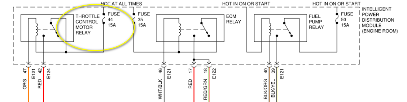
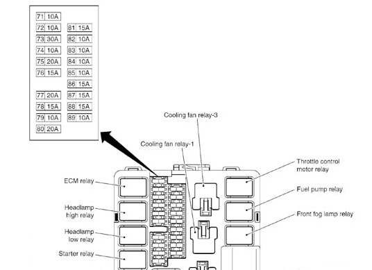
Next, I would suggest that you check fuse F44, 15A, in the IPDM. See image 1 below
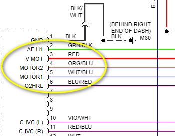
This is the engine fuse block. The fuse supplies constant 12V to the throttle control relay. The relay then supplies 12V, pin 42(red wire) to the ECM, pin 3, which in turn powers the throttle actuator motor.
See image 2 below for the pin out of ECM.
See image 5 below for fuse and relay layout in IPDM.
If fuse F44 is in order, then next check if 12V is present at the ECM pin 3 with KOEO.
This is to establish if the relay is being activated and the red wire from the IPDM pin 42 to ECM pin 3 is intact.
If no 12V is present at ECM pin 3 then next check if 12V is present at IPDM pin 42.
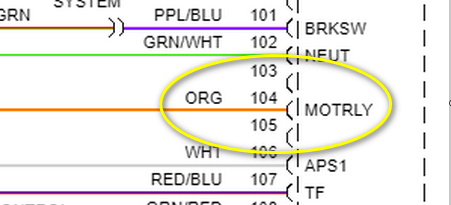
If no 12V is present at IPDM pin 42 then next check if ground/earth is present at IPDM pin 47, orange wire. This ground is a pull-down ground from the ECM on pin 104 to activate the relay
See image 3 below.
How to test wiring.
https://www.2carpros.com/articles/how-to-check-wiring
How to use a voltmeter.
https://www.2carpros.com/articles/how-to-use-a-voltmeter
How to test a fuse
https://www.2carpros.com/articles/how-to-check-a-car-fuse
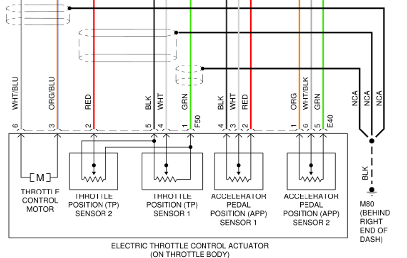
See image 4 below for the throttle control actuator.
If all the above tests do not reveal any faults, then I would suggest testing the two wires from ECM pin 4 +5, white/blue and orange/blue wires, to the throttle control actor pins 6+3
Check the wiring for continuity and resistance. Expect to see less than 5-ohm resistance pin to pin.
Please let us know how you get along.
Cheers, Boris
Images (Click to make bigger)
SPONSORED LINKS
Thursday, February 24th, 2022 AT 1:37 AM