A/C not blowing cold air

Tiny
BOBK123
  • MEMBER
  • 2001 CHEVROLET PRIZM
  • 1.8L
  • 4 CYL
  • 2WD
  • AUTOMATIC
  • 60,000 MILES
A/C is out - no cold air (blower is working, I can get heat). The compressor clutch does not look to be spinning. It looks a bit rusted too, although I can turn it by hand. I checked low pressure side and it reads very high, like 94 PSI. The lines look okay and the evaporator looks okay. Thank you.
Thursday, June 24th, 2021 AT 5:57 AM

30 Replies

Tiny
KASEKENNY
  • MECHANIC
  • 18,907 POSTS
Sounds like the compressor is not engaging at all. For the the low side to be 94 PSI that is pretty normal when the system is static.

When the compressor engages it pulls the low side down and builds the pressure on the high side.

I suspect you have one of two issue. Either the compressor is not functioning due to no power or the compressor has failed.

Let's start with checking for power at the compressor and we can go from there.

https://www.2carpros.com/articles/how-to-check-wiring

I attached the wiring diagram below for your review.

Also here is a guide that will help with more info on this:

https://www.2carpros.com/articles/car-air-conditioner-not-working-or-is-weak

Let me know what questions you have.

Thanks
Was this
answer
helpful?
Yes
No
+1
Thursday, June 24th, 2021 AT 6:38 PM
Tiny
BOBK123
  • MEMBER
  • 17 POSTS
Hi Kenny,

Thanks very much for your reply, and sharing the links and diagrams! I have a multimeter, so I'll check if voltage is getting to the compressor. I'll reply with what I find.
Was this
answer
helpful?
Yes
No
Friday, June 25th, 2021 AT 12:05 PM
Tiny
BOBK123
  • MEMBER
  • 17 POSTS
Hi Kenny,

I see two different harnesses going to the compressor. One has 2 wires, which looks like it matches the wiring diagram, the wires are white/black and blue/yellow (I think yellow, hard to see for sure). I pulled the connector and checked voltage (touched multimeter probe to the inside of the connector where the blue/yellow wire goes.) It reads 0.1 volts with the A/C on or off. Blower is on high when testing. So not getting voltage here.

The other connector has 4 wires. Picture attached - this connector is in place, I didn't pull it off. Do you know what this harness is for? Do I need to check voltage here?

Thanks

PS: the blue/yellow wire looks like it's making a solid connection at the connector - it's not loose or frayed.
Was this
answer
helpful?
Yes
No
Saturday, June 26th, 2021 AT 11:20 AM
Tiny
KASEKENNY
  • MECHANIC
  • 18,907 POSTS
The two wires that you removed and tested is for the compressor clutch and should have 12 volts when the A/C is on.

So we need to go to the relay and check for voltage there and test the relay. Here is a guide that will help with this:

https://www.2carpros.com/articles/how-to-check-an-electrical-relay-and-wiring-control-circuit

I would swap the relay or replace it as that is the likely issue. You can also jump the relay (pin 1 to 3) to see if the compressor comes on. If so then the relay is the issue or the PCM is not grounding the relay but let's start with this and go from there. Thanks
Was this
answer
helpful?
Yes
No
+1
Sunday, June 27th, 2021 AT 8:20 PM
Tiny
BOBK123
  • MEMBER
  • 17 POSTS
Thanks very much I will check the relay tomorrow. In the meantime, to help me understand the wiring diagram, I have a couple of questions. There's another component between the relay and the compressor clutch, Fuse and Relay Block 1 (beneath the relay on the diagram). Is this a fuse? I'm confused because the blue/yellow power wire for the clutch looks like it comes from this component Pin 9, but there's a break between Pin 9 and the clutch, and the wire colors change at this break.
Was this
answer
helpful?
Yes
No
Monday, June 28th, 2021 AT 1:08 AM
Tiny
BOBK123
  • MEMBER
  • 17 POSTS
Hi Kenny,

I have some interesting findings. The relay is good. I swapped it with the relay next to it, (same model relay), and no change. I can also hear a faint click in both relays when the car ignition starts.

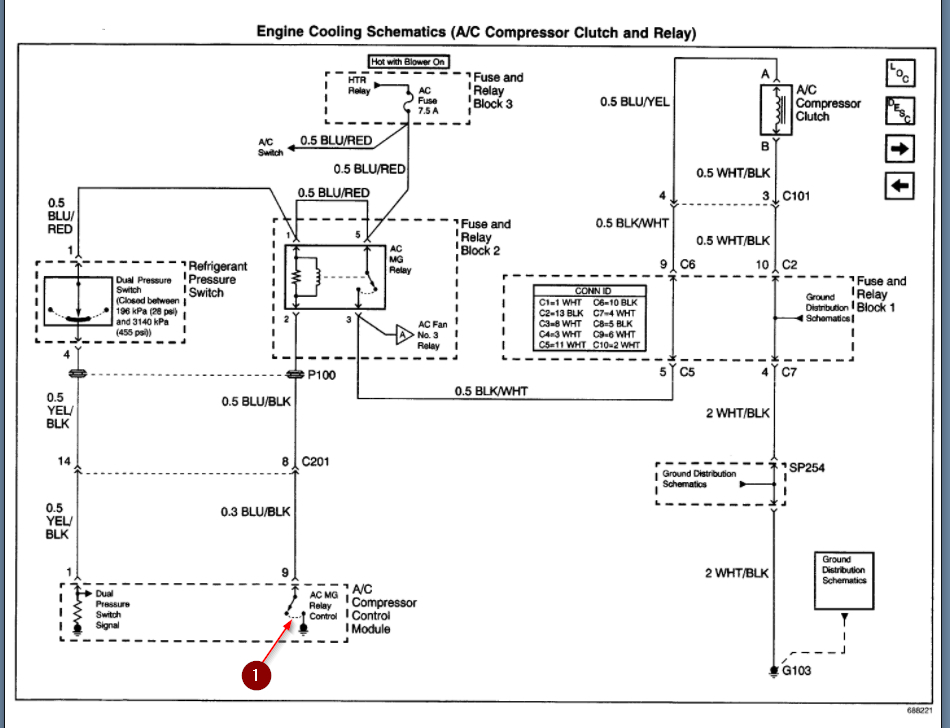
Then I pulled the relay and probed the points. The one point that seems totally off is terminal 85 ground. There's no continuity when I check it with the multimeter's other probe touching battery ground.

As for the other relay points - I think these are correct, assuming the relay switch is not closing:
Terminal 86 reads 14.5v with AC or blower on; no voltage with AC/blower off.
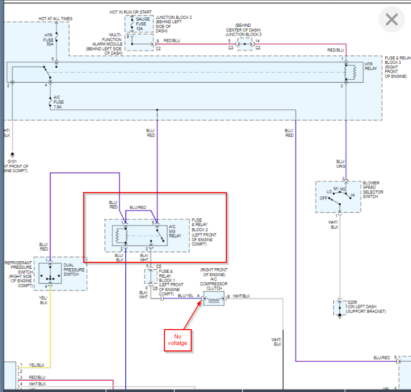
Terminal 87 (output) reads continuity with the compressor chassis, but 0.1v when AC/blower is on or off, so I assume switch is not closing.
Terminal 30 (battery) reads 14.5v with AC on or blower on; no voltage with AC/blower off.

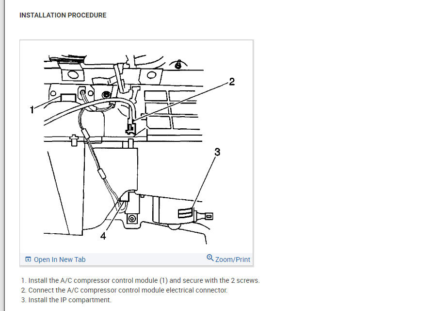
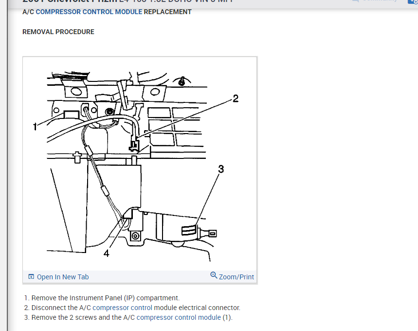
So. Is the problem no ground reaching the relay? On the diagram it looks like it comes from the compressor control module? That part of the diagram is cut off. Please advise as to the next step!

Thank you
Was this
answer
helpful?
Yes
No
Monday, June 28th, 2021 AT 1:07 PM
Tiny
BOBK123
  • MEMBER
  • 17 POSTS
Hi again Kenny,

When I was checking the relay I forgot to jump it, so I did just now - I jumped pin 5 to pin 3 - and the compressor kicked in right away. Clutch is spinning and getting plenty of cold air. :) Low side pressure reads 39 psi. So great to know the compressor and clutch seem to be working.
Was this
answer
helpful?
Yes
No
Monday, June 28th, 2021 AT 5:25 PM
Tiny
KASEKENNY
  • MECHANIC
  • 18,907 POSTS
That is great. Yes. If you jump it and get that operation then that is perfect.

As for the testing that you did on the relay, I suspect you are correct that there is no ground but we need to test it a little differently then you did.

This is not going to have a constant path to ground as the compressor control module controls the compressor by opening the circuit on the ground side. So we call this a low side driver.

Take a look at the wiring diagram below. You are only going to have continuity to ground on that terminal when the control module is closed.

The way to test this is to remove the relay, put your black meter lead on this terminal and then the red meter lead on battery positive. Then turn the engine on and the AC on. Does your meter read battery voltage? If it does then the control module is grounding the circuit. If not, then the control module is the issue.

You are correct that you have.1 volts on the compressor circuit because the relay is not closing.

You need the control module to ground the control side of the relay so that it closes the relay to turn on the compressor.
Was this
answer
helpful?
Yes
No
Tuesday, June 29th, 2021 AT 7:34 PM
Tiny
BOBK123
  • MEMBER
  • 17 POSTS
Thanks very much. From what you say, I understand that I won't see constant ground on terminal 85. I'll see ground only with the control module closed.

What is (and where is) the control module? Is it part of the HVAC unit in the dash? Does turning on the A/C button on the dash directly close the control module?
Was this
answer
helpful?
Yes
No
Tuesday, June 29th, 2021 AT 8:45 PM
Tiny
KASEKENNY
  • MECHANIC
  • 18,907 POSTS
That is correct. It is a ground control relay. That means it is an open circuit until the control module wants it on. Then it applies the ground and that completes the circuit and current flows through the coil in the relay which closes the contacts in the relay and then this allows power to flow to the compressor.

Let me know if you have questions on this. Thanks
Was this
answer
helpful?
Yes
No
+1
Thursday, July 1st, 2021 AT 5:57 PM
Tiny
BOBK123
  • MEMBER
  • 17 POSTS
Thanks for the info! I've been out of town so I haven't been able to test the ground as you suggested, but I'll get to it this weekend. In case the control module does need to be replaced, can you confirm if this is the part?

https://www.amazon.com/ACDelco-15-21529-Original-Equipment-Conditioning/dp/B000EQQMUW

I searched the AC Delco site and this unit came up as the compatible part - HVAC Control Module. But it seems very hard to find - it's out of stock.

thanks!
Was this
answer
helpful?
Yes
No
Thursday, July 1st, 2021 AT 8:34 PM
Tiny
KASEKENNY
  • MECHANIC
  • 18,907 POSTS
Okay. Sounds good. Yes. A/C control module is what you want. The location is number 13 below.

Let us know how you make out but you may need to seek one in a salvage yard.
Was this
answer
helpful?
Yes
No
Friday, July 2nd, 2021 AT 8:31 PM
Tiny
BOBK123
  • MEMBER
  • 17 POSTS
I tested the relay ground as you asked, by turning on the A/C and probing relay ground (terminal 85) and battery +. I read 13.2v. So assuming I'm checking it correctly - which I would like to confirm! - it means the control module is closing. Thing is, when I turn off the AC I still read the same voltage. So I don't know if that makes sense - shouldn't the control module prevent ground from reaching the relay when the A/C is off?

As for the relay terminals, can you please confirm that I'm probing the correct points? I found this diagram https://benignblog.com/denso-relay-wiring-circuit-diagram which matches the relay pretty closely. My relay is Denso starting with 156700. I want to be sure that this webpage diagram is showing the pins on the the relay, and not the slots on the relay connector. The slots on the relay connector would be the mirror image, correct?
Was this
answer
helpful?
Yes
No
Saturday, July 3rd, 2021 AT 5:25 AM
Tiny
KASEKENNY
  • MECHANIC
  • 18,907 POSTS
That does appear to be correct but when you tested this, was the engine running?

Take a look at this attachment. Let's just confirm this is what you are seeing at the control module.

They are having you test it at the module to determine if the module is functioning so they may be using different logic to control this because I would not expect to see no or little voltage when it is operating. However, that is what they are calling for.

It is the blue and black wire on the module.
Was this
answer
helpful?
Yes
No
Saturday, July 3rd, 2021 AT 8:15 PM
Tiny
BOBK123
  • MEMBER
  • 17 POSTS
Engine was running for my tests. Can you just let me know - with A/C off and engine on, should I be getting ground at the A/C MG relay terminal 85?

And I'm not 100% clear on your last message - do I need to access the control module and probe the blue/black wire (terminal 9) at the point where it connects to the module? Since this is ground I assume I will do the same type of test - black probe to control module and red probe to battery +?

As for getting to the control module, I can't find anything online about accessing it. I see the location of the control module from your diagrams. Do you know if I can access it by just removing the glove box?
Was this
answer
helpful?
Yes
No
Sunday, July 4th, 2021 AT 6:53 AM
Tiny
KASEKENNY
  • MECHANIC
  • 18,907 POSTS
Yes. We need to access the control module and test this as we need to do it with the relay installed. I suspect the control module is the issue but there may be a resistor inside the module that is not sensing the resistor installed and so it is not commanding the relay to close. This is not a traditional simple grounding circuit within the module or you would be getting the opposite voltage when the A/C is off.

If you remove the glove box you should be able to access it. Take a look at the attachment below. You test this by red lead in this blue/black wire and the black lead on ground (pin 4) so you can monitor the voltage.

We might as well check each of them. Here are what the expected values for each wire. Let us know what each value is with the system in the condition noted in the last column.
Was this
answer
helpful?
Yes
No
Sunday, July 4th, 2021 AT 10:03 AM
Tiny
BOBK123
  • MEMBER
  • 17 POSTS
I located the module and checked voltage on all the terminals - see attached for results!
I did what you suggested, black probe touching wire 4 ground, and red probe to each of the other wires one at a time, following the conditions stated.

Terminal 9 Relay Control is definitely off from the normal voltage in both conditions. Of the others, some are reading correct and others are off.
Was this
answer
helpful?
Yes
No
Monday, July 5th, 2021 AT 11:23 AM
Tiny
KASEKENNY
  • MECHANIC
  • 18,907 POSTS
Wait a minute. You have 0 volts on the pressure switch circuit (pin 1). That explains why we are seeing the odd voltage that did not make sense and I assumed there was logic in the module that was using these voltages differently. This should be 12 volts any time the key is on and you have 0 which means the pressure switch is either faulty or the pressures are not accurate.

This also explains why when you put power to the compressor it comes on because you are basically bypassing this sensor.

I would replace the pressure sensor and then check the operation of the compressor again because it appears you already checked the pressures and they are fine. That should set the voltages back to what they should be.
Was this
answer
helpful?
Yes
No
Tuesday, July 6th, 2021 AT 5:48 PM
Tiny
BOBK123
  • MEMBER
  • 17 POSTS
Okay, sounds good! Can you confirm if this is the correct part? https://www.gmpartsbin.com/p/Chevrolet_2001_Prizm-LSi-Sedan-18L-AT/HVAC-Pressure-Switch/48817117/52484739.html
Was this
answer
helpful?
Yes
No
Wednesday, July 7th, 2021 AT 8:13 AM
Tiny
KASEKENNY
  • MECHANIC
  • 18,907 POSTS
Sorry for the delay. That looks like it.

I attached the OEM part number below from the manual just for reference but it is the same number so you are good to go.
Was this
answer
helpful?
Yes
No
Thursday, July 8th, 2021 AT 8:37 AM

Please login or register to post a reply.

Sponsored links