Good morning,
Can I have the code numbers that were set?
https://www.2carpros.com/articles/checking-a-service-engine-soon-or-check-engine-light-on-or-flashing
What did you mean by wired directly? What voltage did you put to the sensors?
https://www.2carpros.com/articles/how-a-knock-sensor-works
Can you upload a video of the noise when it returns?
https://www.2carpros.com/articles/engine-noises
Did you check the fuel pressure?
https://www.2carpros.com/articles/car-cranks-but-wont-start
https://www.2carpros.com/articles/how-to-check-fuel-system-pressure-and-regulator
All of these could be a contributing factor to the issue.
Roy
KNOCK SENSOR (KS) SYSTEM DESCRIPTION
PURPOSE
The knock sensor (KS) system enables the control module to control the ignition timing for the best possible performance while protecting the engine from potentially damaging levels of detonation. The control module uses the KS system to test for abnormal engine noise that may indicate detonation, also known as spark knock.
SENSOR DESCRIPTION
This knock sensor (KS) system uses one or 2 broadband one-wire sensors. The sensor uses piezo-electric crystal technology that produces an AC voltage signal of varying amplitude and frequency based on the engine vibration, or noise, level. The amplitude and frequency are dependant upon the level of knock that the KS detects. The control module receives the KS signal through a signal circuit. The KS ground is supplied by the engine block through the sensor housing.
One way the control module monitors the system is by output of a bias voltage on the KS signal wire. The bias voltage creates a voltage drop that the control module monitors and uses to help diagnose KS faults. The KS noise signal rides along this bias voltage, and due to the constantly fluctuating frequency and amplitude of the signal, will always be outside of the bias voltage parameters.
Another way the control module monitors the system is by learning the average normal noise output from the KS. The control module learns a minimum noise level, or background noise, at idle from the KS and uses calibrated values for the rest of the RPM range. The control module uses the minimum noise level to calculate a noise channel. The control module uses this noise channel, and the KS signal that rides along the noise channel, in much the same way as the bias voltage type does. As engine speed and load change, the noise channel upper and lower parameters will change to accommodate the normal KS signal.
In order to determine which cylinders are knocking, the control module only uses KS signal information when each cylinder is near top dead center (TDC) of the firing stroke. If the control module has determined that knock is present, it will retard the ignition timing to attempt to eliminate the knock. The control module will always try to work back to a zero compensation level, or no spark retard. An abnormal KS signal will fall within the noise channel or will not be present. KS diagnostics are calibrated to detect faults with the KS circuitry inside the control module, the KS wiring, or the KS voltage output.
KNOCK SENSOR (KS) REPLACEMENT
REMOVAL PROCEDURE
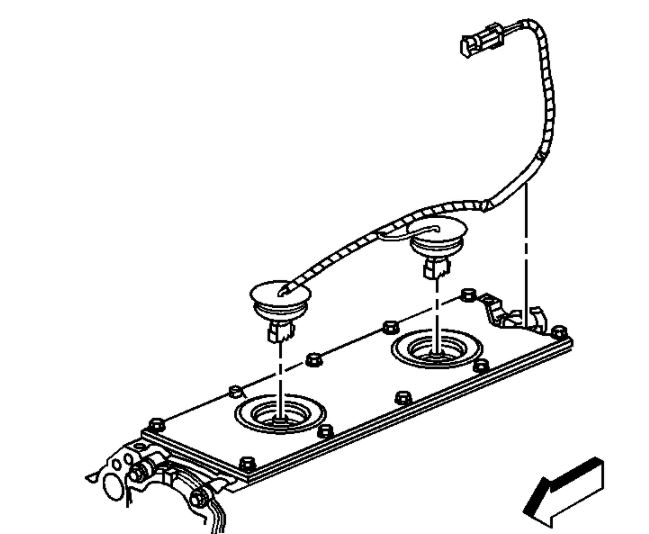
imageOpen In New TabZoom/Print
1. Remove the intake manifold.
2. Gently pry up the rubber covers.
3. Disconnect the knock sensor electrical connectors.
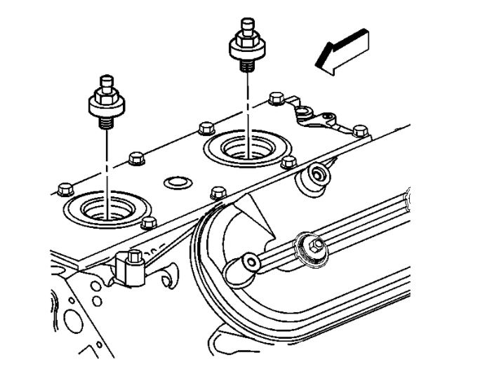
imageOpen In New TabZoom/Print
4. Remove the knock sensors.
Images (Click to make bigger)
SPONSORED LINKS
Friday, January 15th, 2021 AT 3:50 AM