Hi,
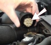
It sounds like the head gasket is bad. Is there evidence of coolant mixing with the engine oil? It will have a tan creamy appearance. Take a look through this link. It explains how to check for a bad head gasket. You will see pics of what I'm referring to.
https://www.2carpros.com/articles/head-gasket-blown-test
If there is coolant mixed, it's likely that the bearings were damaged. When it is now running, is there any knocking or ticking from the engine?
_________________________________________________
1996 Ford Mustang V6-232 3.8L
Removal and Installation
Vehicle Engine, Cooling and Exhaust Engine Cylinder Head Assembly Service and Repair Procedures Removal and Installation
REMOVAL AND INSTALLATION
REMOVAL
1. Drain engine cooling system, then disconnect battery ground cable.
2. Remove air cleaner outlet tube from throttle body as follows:
a. Disconnect wire harness from intake air temperature sensor, then crankcase ventilation tube from air cleaner outlet tube.
b. Loosen air cleaner tube clamps on outlet tube, then disconnect outlet tube from throttle body.
c. Disconnect outlet tube from mass airflow sensor, then remove tube.
3. Loosen drive belt tensioner, then remove drive belts.
4. On left hand cylinder head, proceed as follows:
a. Remove oil filler cap.
b. Remove power steering pump front mounting bracket bolts.
c. Remove generator, then belt idler pulley.
d. Remove power steering pump/generator bracket bolts, then place pump/bracket assembly aside, with hoses connected, in position to prevent fluid leakage.
5. On righthand cylinder head, proceed as follows:
a. Remove drive belt.
b. Remove A/C mounting bracket bolts, then place A/C compressor aside with hoses connected.
c. Remove positive crankcase ventilation valve.
6. Remove upper intake manifold.
7. Remove valve cover.
8. Remove fuel injection supply manifold.
9. Remove lower intake manifold.
10. Remove exhaust manifolds.
11. Loosen rocker arm fulcrum bolts enough to allow rocker arm to be lifted off push rod, and rotate to one side.
12. Remove push rods, then identify position of each push rod. Push rods should be installed in their original positions during assembly.
13. Remove cylinder head bolts, then cylinder heads. Discard bolts.
14. Remove and discard old head gaskets.
INSTALLATION
CAUTION: Always use new cylinder head bolts to ensure a leak-proof assembly. Torque retention with used bolts can vary, which may result in coolant or compression leakage at cylinder head mating surface area.
1. Prepare cylinder head components as follows:
a. Lightly oil all bolts and stud bolt threads before installation, except those specifying special sealant.
b. Clean cylinder head, intake manifold, rocker arm cover and head gasket surfaces. If cylinder head was removed for head gasket replacement, check flatness of cylinder head and cylinder block gasket surfaces.
2. Position new head gasket(s) onto cylinder block using dowels for alignment, then position cylinder heads onto cylinder block.
FWD 3.8L
pic 1
3. Reassemble and tighten the new head bolts to the following specifications:
Tighten all bolts in numerical sequence, as shown, in three steps as follows:
- 20 Nm (15 lb-ft)
- 40 Nm (30 lb-ft)
- 50 Nm (37 lb-ft)
Caution: Do not loosen all of the bolts at the same time. Work on one bolt at a time in the sequence shown. Failure to loosen bolts in proper sequence could cause cylinder head to warp.
4. In numerical sequence, retighten the bolts per the fallowing steps:
Long Bolts:
a. Loosen the long bolt and back out 2-3 revolutions.
b. Retighten the long bolt to 40-50 Nm (29-37 lb-ft).
c. Rotate the long bolt an additional 180°.
d. Go to the next bolt in sequence.
Short Bolts:
a. Loosen the short bolt and back out 2-3 revolutions.
b. Retighten the short bolt to 15-25 Nm (11-18 lb-ft).
c. Rotate the short bolt an additional 180°.
d. Go to the next bolt in sequence.
5. Dip each push rod end in engine assembly lubricant D9AZ-19579-D or equivalent.
6. Install push rods in their original positions, then lubricate all rocker arms with engine assembly lubricant D9AZ-19579-D or equivalent.
7. Install rocker arms.
8. Install exhaust manifolds.
9. Install lower intake manifold.
10. Install fuel injection supply manifold.
11. Position valve cover on cylinder head and install bolts. Note location of ignition wire routing clip stud bolts.
12. Install upper intake manifold.
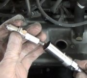
13. Install spark plugs, then connect ignition wires to spark plugs.
14. On lefthand cylinder head, proceed as follows;
a. Install oil filler cap.
b. Install generator/power steering pump mounting bracket, then generator.
c. Install accessory drive belt tensioner.
d. Install power steering pump and support bracket, then tighten to specifications.
15. On righthand cylinder head, proceed as follows:
a. Install positive crankcase ventilation valve.
b. Install A/C compressor mounting and supporting brackets, then compressor.
16. Install drive belt.
17. Connect battery ground cable.
18. Install air cleaner outlet tube as follows:
a. Install outlet tube, then connect tube to mass airflow sensor.
b. Connect outlet tube to throttle body, then tighten air cleaner tube clamps on outlet tube.
c. Connect crankcase ventilation tube to air cleaner outlet tube, then wire harness to intake air temperature sensor.
19. Fill engine cooling system with specified coolant.
NOTE: This engine has aluminum cylinder heads and requires a special corrosion inhibited coolant formulation to avoid cooling system damage.
20. Start engine and check for coolant, fuel and oil leaks.
__________________
Here are the directions for the upper and lower intake manifolds. I'm including them so you have the torque specs.
__________________
1996 Ford Mustang V6-232 3.8L
Upper
Vehicle Engine, Cooling and Exhaust Engine Intake Manifold Service and Repair Procedures Upper
UPPER
Removal
1. Remove air cleaner outlet tube (9B659).
2. Disconnect accelerator cable (9A758) at throttle body (9E926). Disconnect speed control actuator cable (9A825) (if equipped).
3. Remove retaining bolts from oil pressure gauge (9273) and position cables aside.
4. Disconnect vacuum lines at upper intake manifold (9424).
5. Disconnect necessary electrical connectors.
6. Disconnect crankcase ventilation tube (6758) at the upper intake manifold and at positive crankcase ventilation valve (PCV valve) (6A666).
7. Remove throttle body if necessary.
8. Remove the EGR valve (EGR valve) (9D475) from the upper intake manifold.
9. Remove the nut and bolt retaining engine support and wiring retainer bracket located at the LH front of the intake manifold and set aside with ignition wires.
10. Remove upper intake manifold retaining bolts/studs.
pic 2
11. Remove upper intake manifold and intake manifold upper gasket (9H486).
Installation
NOTE: Use locating pins to secure position of intake manifold upper gasket between upper intake manifold and lower intake manifold.
NOTE: When the upper intake manifold is removed, always use a new intake manifold upper gasket upon reassembly.
1. Position new intake manifold upper gasket and upper intake manifold on top of lower intake manifold.
NOTE: Apply a light coat of Pipe Sealant with Teflon D8AZ-19554-A or equivalent meeting Ford specification WSK-M2G350-A2 and ESR-M18P7-A to retaining bolts and stud bolt threads prior to installation.
2. Install bolts and stud bolts in original locations.
Tighten in sequence as shown under Removal Step 11, in three steps:
- 10 Nm (8 Lb-Ft)
- 20 Nm (15 Lb-Ft)
- 32 Nm (23 Lb-Ft)
3. Install engine support and wiring bracket and retaining nut and bolt to LH front of the upper intake manifold. Tighten retainers to 20-30 Nm (15-22 lb-ft).
4. Install the EGR valve.
pic 3
5. Install new throttle body gasket (TB gasket) (9E936), throttle body if removed. Cross-tighten retaining nuts to 20-30 Nm (15-22 lb-ft).
6. Connect crankcase ventilation tube to positive crankcase ventilation valve on the upper intake manifold.
7. Connect necessary fuel charging wiring connectors.
8. Connect necessary vacuum hoses.
9. Position accelerator cable bracket (9723). Install and tighten retaining bolts to 14-20 Nm (10-14 lb-ft).
10. Connect accelerator cable at throttle body. Connect speed control actuator cable (if equipped).
11. Install air cleaner outlet tube.
12. Check and adjust accelerator cable if necessary.
13. Check and, if necessary, adjust engine idle airflow.
14. Check and adjust speed control actuator cable if necessary.
_____________________________
Here are the lower intake directions.
1996 Ford Mustang V6-232 3.8L
Lower
Vehicle Engine, Cooling and Exhaust Engine Intake Manifold Service and Repair Procedures Lower
LOWER
Removal
1. Drain engine cooling system.
2. Remove upper intake manifold as outlined.
pic 4
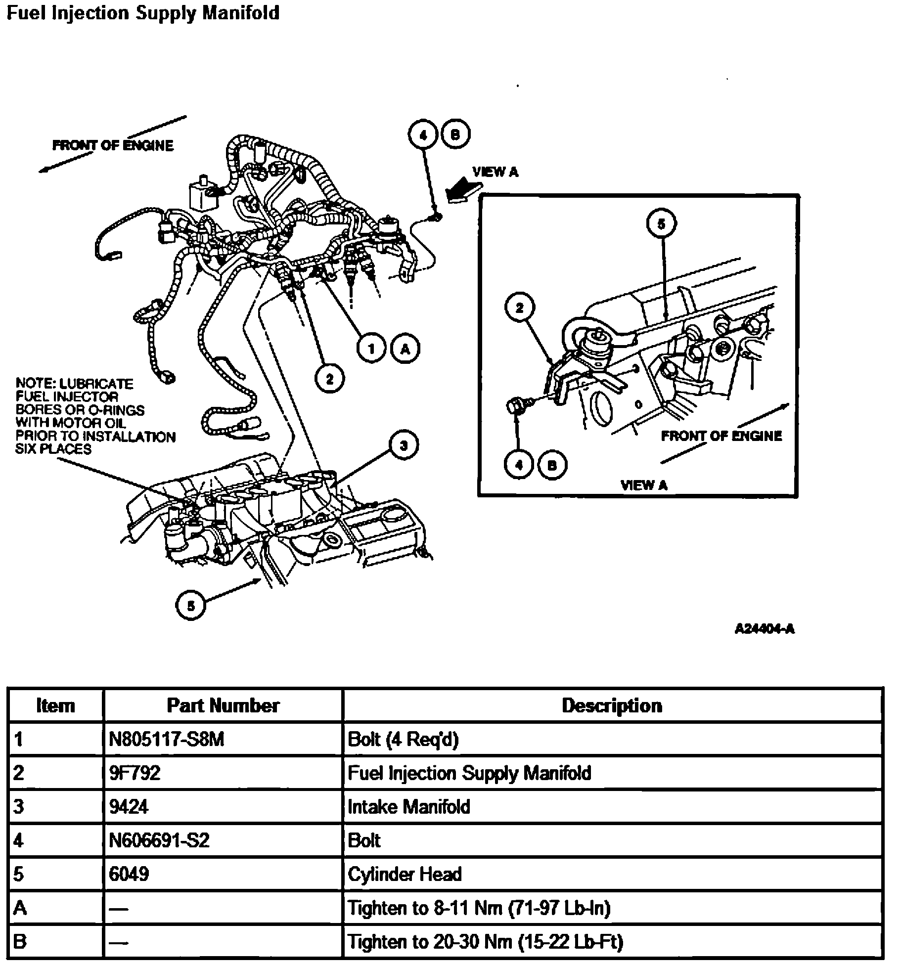
3. Remove fuel injectors (9F593) and fuel injection supply manifold (9F792).
4. Remove heater water outlet hose.
5. Remove lower intake manifold retaining bolts/studs.
CAUTION: The lower intake manifold is sealed at each end with silicone sealer. To break the seal, it may be necessary to pry on the front of the lower intake manifold with a prybar. If it is necessary to pry on the lower intake manifold, use care to prevent damage to machined surfaces.
6. Remove lower intake manifold.
7. Remove and discard intake manifold gaskets (9439) and end seals.
pic 5
8. If lower intake manifold is to be disassembled, perform the following:
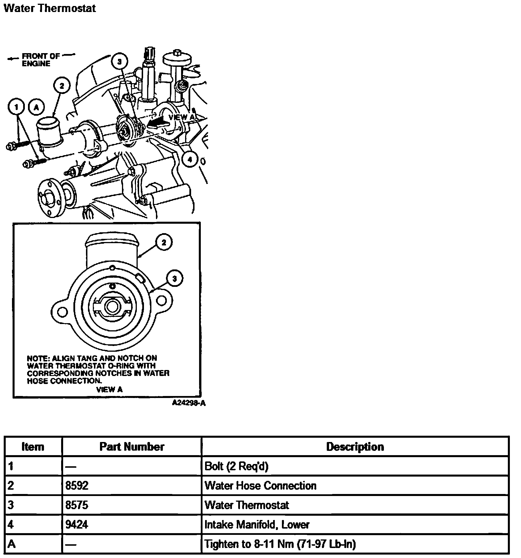
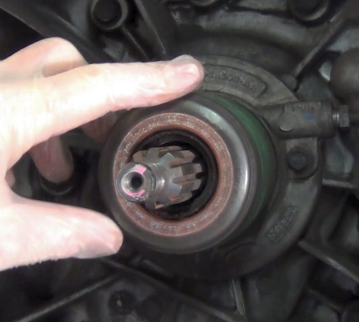
- Remove clutch pressure plate (7563) and water thermostat (8575).
- Remove engine coolant temperature sensor (ECT sensor) (12A648).
- Remove heater elbow.
- Remove all vacuum and electrical fittings.
Installation
NOTE: Lightly oil all retaining bolt and stud threads before installation with clean engine oil meeting Ford specification ESE-M2C153-E.
1. The lower intake manifold cylinder head and cylinder block mating surfaces should be clean and free of old gasketing material. Use a suitable solvent to clean these surfaces.
2. If lower intake manifold was disassembled:
a. Apply Pipe Sealant with Teflon D8AZ-19554-A or equivalent meeting Ford specification WSK-M2G350-A2 and ESR-M18P7-A to the threads of the engine coolant temperature sensor, all vacuum fittings, heater elbows, and electrical fittings (if equipped).
b. Install clutch pressure plate (note direction) and water thermostat. Install water hose connection (8592). Tighten retaining bolts to 8-11 Nm (71-97 lb-in).
NOTE: Prior to applying sealer, clean sealing surfaces of cylinder heads (6049) and lower intake manifold with Metal Surface Cleaner F4AZ-19A536-RA or equivalent meeting Ford specification WSE-M5B392-A to remove all residues that may interfere with the sealer's ability to adhere.
NOTE: When the lower intake manifold is removed, always use new intake manifold gaskets upon reassembly.
NOTE: When using silicone sealer, assembly must occur within 15 minutes after sealer application. After this time, the sealer may start to set up, and its sealing effectiveness may be reduced.
3. Apply a 3-4 mm (0.125 inch) bead of Silicone Rubber D6AZ-19562-AA (clear) or equivalent meeting Ford specifications ESB-M4G92-A and ESE-M4G195-A or F4AZ-19562-B (black) meeting Ford specification WSE-M4G323-A1 at each corner where the cylinder head joins the cylinder block (6010).
4. Install new front and rear intake manifold end seals.
pic 6
5. Install new intake manifold gaskets.
6. Carefully lower intake manifold into position on cylinder block and cylinder head. Use locating pins as necessary to guide lower intake manifold.
pic 7
7. Install bolts and stud bolt in their original locations.
pic 8
8. Tighten bolts and stud bolts in numerical sequence to the following specifications in two steps:
a. 8 Nm (71 lb-in).
b. 12 Nm (106 lb-in).
9. Install front crankcase ventilation tube so that the mounting bracket sits over the lower intake manifold stud. Tighten nut on stud to 20-30 Nm (15-22 lb-ft).
10. Install fuel injectors and fuel injection supply manifold. Tighten fuel injection supply manifold to lower intake manifold bolts to 8-11 Nm (71-97 lb-in). Tighten fuel pressure bracket bolt to 20-30 Nm (15-22 lb-ft).
11. Install upper intake manifold as outlined.
CAUTION: This engine has aluminum cylinder heads and requires a special corrosion inhibiting coolant to avoid cooling system damage.
12. Fill engine cooling system.
13. Start engine and check for leaks.
_________________________
Let me know if this helps or if you have other questions.
Take care,
Joe
Images (Click to make bigger)
Wednesday, December 2nd, 2020 AT 9:05 AM
(Merged)