That's the problem. Either it is stretched or the tensioner is bad. The chain tensioner is actuated by oil pressure and they can go bad.
Now, this is an interference engine, meaning there isn't enough clearance between the piston and valves. If timing is off, it will (in most cases) cause internal engine damage (bent valves).
You have two choices. First, remove the head and inspect the valves for evidence of damage. Or, replace the timing chain and check engine compression.
With that, here are the directions for removing the cylinder head. All attached pictures correlate with these directions. First are the directions for head removal. Next, there are two sets of timing chain removal and replacement procedures. The first is for the PZEV model engine and the second for the non PZEV.
_______________________________________
Cylinder Head Removal (DIAGRAMS AT THE BOTTOM OF POST)
NOTE:
- Use fender covers to avoid damaging painted surfaces.
- To avoid damage, unplug the wiring connectors carefully while holding the connector portion.
- Connect the Honda Diagnostic System (HDS) to the data link connector (DLC), and monitor the engine coolant temperature (ECT) sensor 1. To avoid damaging the cylinder head, wait until the ECT sensor 1 temperature drops below 100 °F (38 °C) before loosening the cylinder head bolts.
- Mark all wiring and hoses to avoid misconnection. Also, be sure that they do not contact other wiring or hoses, or interfere with other parts.
1. Remove the strut brace (if equipped). See: Structural Brace > Removal and Replacement > Frame Brace Replacement
2. Relieve the fuel pressure. See: Fuel Pressure Release > Procedures
3. Drain the engine coolant. See: Coolant > Removal and Replacement
4. Remove the drive belt. See: Drive Belt > Removal and Replacement > Drive Belt Removal/Installation
5. Remove the intake manifold.
6. Remove the catalytic converter. See: Catalytic Converter > Removal and Replacement > Warm Up TWC Removal/Installation
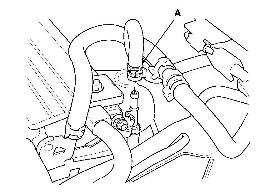
7. Disconnect the evaporative emission (EVAP) canister hose (A).
Pic 1
8. Remove the quick-connect fitting cover (A), then disconnect the fuel feed hose (B). See: Fuel Line Coupler > Removal and Replacement > Fuel Line/Quick-Connect Fitting Removal
Pic 2
9. Disconnect the four fuel injector connectors (A), the engine mount control solenoid valve connector (B), and remove the ground cables (C).
Pic 3
10. Remove the four bolts securing the EVAP canister purge valve bracket.
Pic 4
11. Disconnect the upper radiator hose (A), the heater hoses (B), and the water bypass hose (C).
Pic 5
12. Remove the two bolts (A) securing the connecting pipe.
13. Disconnect the water bypass hose (B).
14. Disconnect the following engine wire harness connectors and wire harness clamps from the cylinder head:
- Engine coolant temperature (ECT) sensor 1 connector
- Camshaft position (CMP) sensor A (Intake) connector
- Camshaft position (CMP) sensor B (Exhaust) connector
- Two rocker arm oil control solenoid connectors
- Two rocker arm oil pressure switch connectors
- EVAP canister purge valve connector
- Variable valve timing control (VTC) oil control solenoid valve connector
- Engine oil pressure switch connector
15. Remove the cam chain. See: Timing Chain > Removal and Replacement > Cam Chain Removal (PZEV Model)
16. Remove the rocker arm assembly. See: Cylinder Head Assembly > Overhaul > Rocker Arm Assembly Removal (PZEV Model)
Pic 6
17. Remove the cylinder head bolts. To prevent warpage, loosen the bolts in sequence 1/3 turn at a time; repeat the sequence until all bolts are loosened.
18. Remove the cylinder head.
Pic 7
_________________________________________________
Cylinder Head Installation
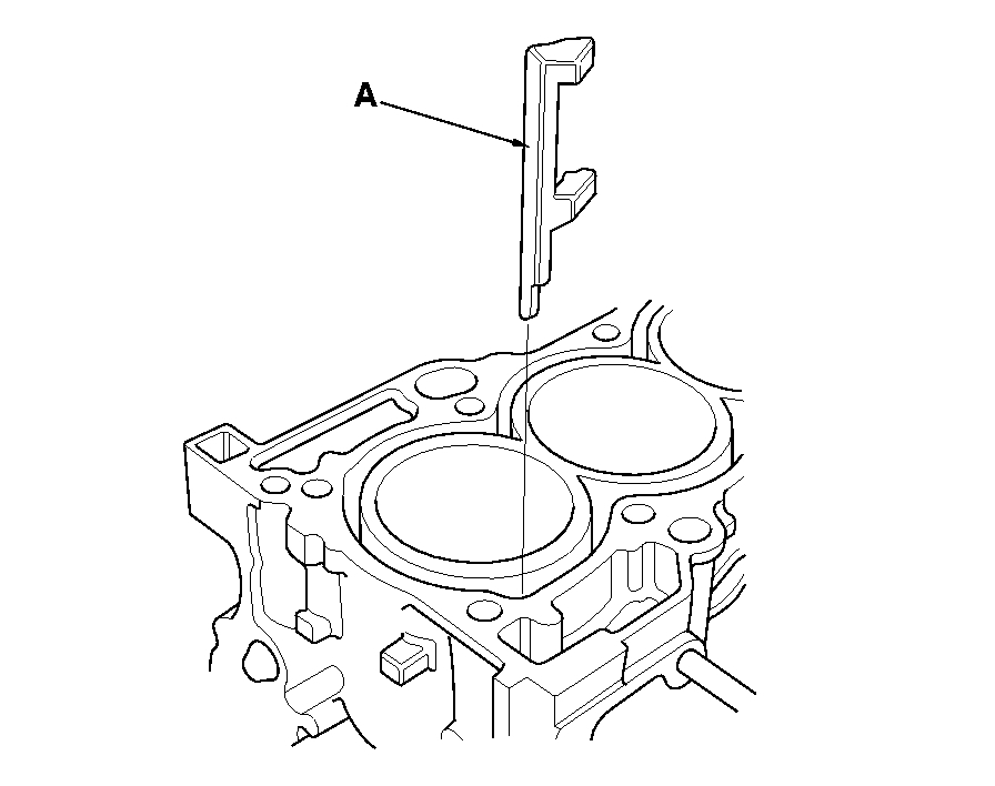
1. Install a new coolant separator (A) in the engine block whenever the engine block is replaced.
2. Clean the cylinder head and the engine block surface.
Pic 8
3. Install the new cylinder head gasket (A) and the dowel pins (B) on the engine block. Always use a new cylinder head gasket.
Pic 9
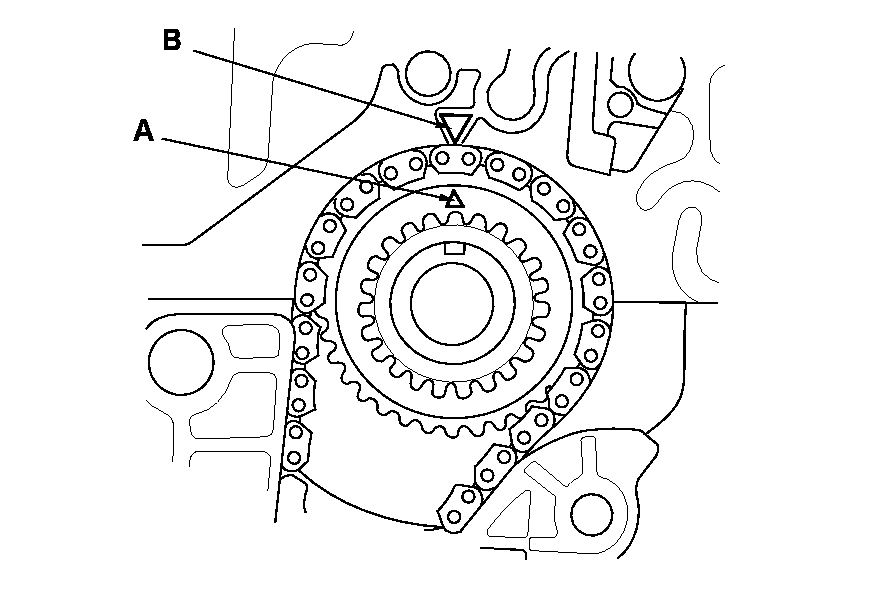
4. Set the crankshaft to top dead center (TDC). Align the TDC mark (A) on the crankshaft sprocket with the pointer (B) on the engine block.
5. Install the cylinder head on the engine block.
Pic 10
6. Measure the diameter of each cylinder head bolt at point A and point B.
7. If either diameter is less than 10.6 mm (0.42 in.), Replace the cylinder head bolt.
8. Apply new engine oil to the threads and under the bolt heads of all cylinder head bolts.
Pic 11
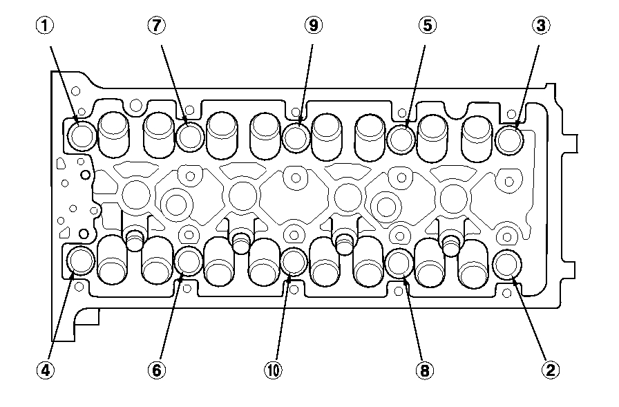
9. Tighten the cylinder head bolts in sequence to 39 N-m (4.0 kgf-m, 29 lbf-ft). Use a beam-type torque wrench. When using a preset click-type torque wrench, be sure to tighten slowly and do not overtighten. If a bolt makes any noise while you are torquing it, loosen the bolt and retighten it from the first step.
Pic 12
10. After torquing, tighten all cylinder head bolts in two steps (90 ° per step) using the sequence shown in step 9. If you are using a new cylinder head bolt, tighten the bolt an extra 90 °.
NOTE: Remove the cylinder head bolt if you tightened it beyond the specified angle, and go back to step 6 of the procedure. Do not loosen it back to the specified angle.
11. Install the rocker arm assembly. See: Cylinder Head Assembly > Overhaul > Rocker Arm Assembly Installation (PZEV Model)
12. Install the cam chain. See: Timing Chain > Removal and Replacement > Cam Chain Installation (PZEV Model)
13. Connect the following engine wire harness connectors, and install the wire harness clamps to the cylinder head:
- Engine coolant temperature (ECT) sensor 1 connector
- Camshaft position (CMP) sensor A (Intake) connector
- Camshaft position (CMP) sensor B (Exhaust) connector
- Two rocker arm oil control solenoid connectors
- Two rocker arm oil pressure switch connectors
- Evaporative emission (EVAP) canister purge valve connector
- Variable valve timing control (VTC) oil control solenoid valve connector
- Engine oil pressure switch connector
Pic 13
14. Install the two bolts (A) securing the connecting pipe.
15. Connect the water bypass hose (B).
Pic 14
16. Connect the upper radiator hose (A), the heater hoses (B), and the water bypass hose (C).
Pic 15
17. Install the four bolts securing the EVAP canister purge valve bracket.
Pic 16
18. Connect the four fuel injector connectors (A), the engine mount control solenoid valve connector (B), and install the ground cables (C).
Pic 17
19. Connect the fuel feed hose (A), See: Fuel Line Coupler > Removal and Replacement > Fuel Line/Quick-Connect Fitting Installation then install the quick-connect fitting cover (B).
Pic 18
20. Connect the EVAP canister hose (A).
21. Install the catalytic converter. See: Catalytic Converter > Removal and Replacement > Warm Up TWC Removal/Installation
22. Install the intake manifold.
23. Install the drive belt. See: Drive Belt > Removal and Replacement > Drive Belt Removal/Installation
24. Install the strut brace (if equipped). See: Structural Brace > Removal and Replacement > Frame Brace Replacement
25. After installation, check that all tubes, hoses, and connectors are installed correctly.
26. Inspect for fuel leaks. Turn the ignition switch to ON (II) (do not operate the starter) so the fuel pump runs for about 2 seconds and pressurizes the fuel line. Repeat this operation three times, then check for fuel leakage at any point in the fuel line.
27. Refill the radiator with engine coolant, and bleed the air from the cooling system with the heater valve open. See: Coolant > Removal and Replacement
28. Check for fluid leaks.
29. Do the powertrain control module (PCM) idle lean procedure. See: Engine Control Module > Programming and Relearning > ECM/PCM Idle Learn Procedure
30. Do the crankshaft position (CKP) pattern clear/CKP pattern lean procedure. See: Computers and Control Systems > Initial Inspection and Diagnostic Overview
31. Inspect the idle speed. See: Idle Speed > Component Tests and General Diagnostics
32. Inspect the ignition timing. See: Ignition Timing > Component Tests and General Diagnostics
Pic 19
___________________________
Here are the directions for chain replacement: (PZEV Model)
Cam Chain Removal
NOTE: Keep the cam chain away from magnetic fields.
1. Remove the front wheels.
2. Remove the splash shield. See: Engine > Removal and Replacement > Engine Removal
3. Remove the drive belt. See: Drive Belt > Removal and Replacement > Drive Belt Removal/Installation
4. Remove the cylinder head cover. See: Valve Cover > Removal and Replacement > Cylinder Head Cover Removal (PZEV Model)
5. Set the No. 1 piston at top dead center (TDC). The punch mark (A) on the variable valve timing control (VTC) actuator and the punch mark (B) on the exhaust camshaft sprocket should be at the top. Align the TDC marks (C) on the VTC actuator and the exhaust camshaft sprocket.
Pic 20
6. Disconnect the VTC oil control solenoid valve connector (A) and remove the harness clamp (B).
7. Remove the VTC oil control solenoid valve. See: Variable Valve Timing Actuator > Removal and Replacement > VTC Oil Control Solenoid Valve Removal/Test/Installation
8. Remove the crankshaft pulley. See: Harmonic Balancer - Crankshaft Pulley > Removal and Replacement > Crankshaft Pulley Removal and Installation (PZEV Model)
9. Support the engine with a jack and a wood block under the oil pan.
Pic 21
10. Remove the ground cable (A), then remove the side engine mount bracket (B).
Pic 22
11. Remove the side engine mount bracket mounting bolts.
Pic 23
12. Remove the cam chain case (A) and spacer (B).
13. Loosely install the crankshaft pulley.
Pic 24
14. Turn the crankshaft counterclockwise to compress the auto-tensioner.
Pic 25
15. Align the holes on the lock (A) and the auto-tensioner (B), then insert a 1.2 mm (0.05 in.) Diameter pin or lock pin (P/N 14511-PNA-003) (C) into the holes. Turn the crankshaft clockwise to secure the pin.
NOTE: Check the auto-tensioner cam position. If the position are not aligned, set the first cam to the first edge of the rack.
Pic 26
16. Remove the auto-tensioner.
Pic 27
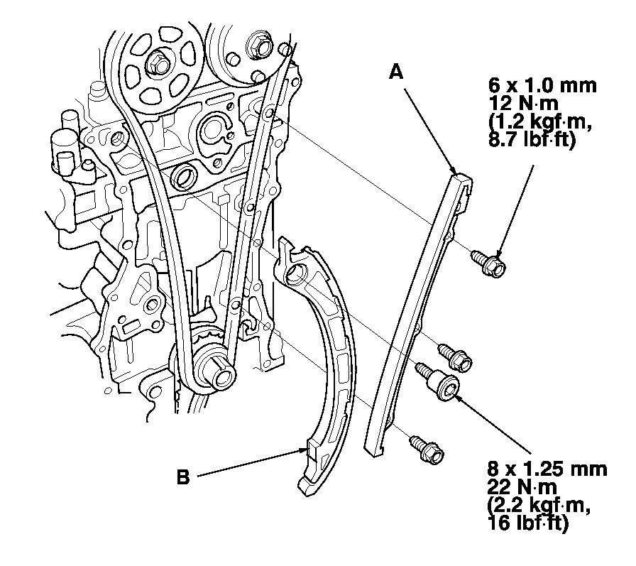
17. Remove cam chain guide B.
Pic 28
18. Remove cam chain guide A and the tensioner arm (B).
19. Remove the cam chain.
Pic 29
_____________________
Cam Chain Installation
Special Tools Required
- Camshaft lock pin set 07AAB-RWCA120
NOTE:
- Keep the cam chain away from magnetic fields.
- Before doing this procedure, check that the variable valve timing control (VTC) actuator is locked by turning the VTC actuator counterclockwise. If not locked, turn the VTC actuator clockwise until it stops, then recheck it. If it is still not locked, replace the VTC actuator.
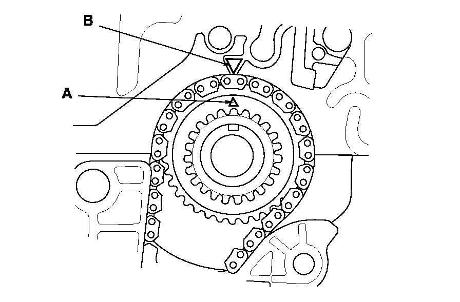
1. Set the crankshaft to top dead center (TDC). Align the TDC mark (A) on the crankshaft sprocket with the pointer (B) on the engine block.
Pic 30
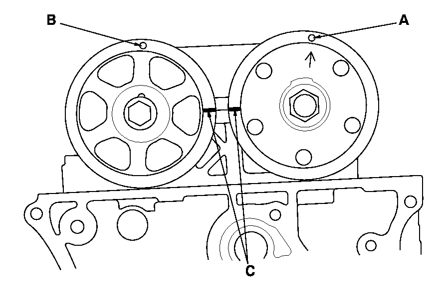
2. Set the camshafts to TDC. The punch mark (A) on the VTC actuator and the punch mark (B) on the exhaust camshaft sprocket should be at the top. Align the TDC marks (C) on the VTC actuator and the exhaust camshaft sprocket.
Pic 31
3. To hold the intake camshaft, insert a camshaft lock pin (P/N 07AAB-RWCA120) (A) into the maintenance hole in camshaft position (CMP) pulse plate A (B) and through the No. 5 rocker shaft holder (C).
4. To hold the exhaust camshaft, insert a camshaft lock pin (A) into the maintenance hole in CMP pulse plate B (D) and through the No. 5 rocker shaft holder (C).
Pic 32
5. Install the cam chain on the crankshaft sprocket with the colored link plate (A) aligned with the mark (B) on the crankshaft sprocket.
Pic 33
6. Install the cam chain on the VTC actuator and the exhaust camshaft sprocket with the punch marks (A) aligned with the center of the two colored link plates (B).
Pic 34
7. Install cam chain guide A and the tensioner arm (B).
Pic 35
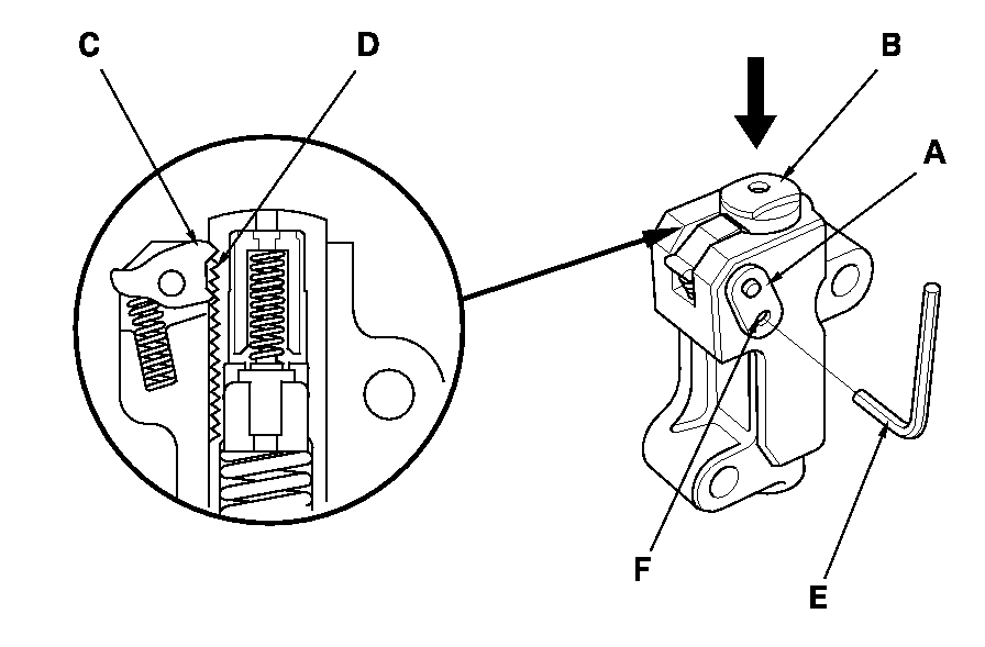
8. Compress the auto-tensioner when replacing the cam chain. Remove the pin from the auto-tensioner. Turn the plate (A) counterclockwise, to release the lock, then press the rod (B), and set the first cam (C) to the first edge of the rack (D). Insert the 1.2 mm (0.05 in.) Diameter pin or lock pin (P/N 14511-PNA-003) (E) into the holes (F).
NOTE: If the chain tensioner is not set up as described, the tensioner will become damaged.
Pic 36
9. Install cam chain guide B.
Pic 37
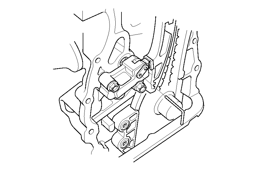
10. Install the auto-tensioner.
NOTE: Check the auto-tensioner cam position. If the position are not aligned, set the first cam to the first edge of the rack.
Pic 38
11. Remove the pin or lock pin from the auto-tensioner.
Pic 39
12. Remove the camshaft lock pin set.
13. Check the chain case oil seal for damage. If the oil seal is damaged, replace the chain case oil seal. See: Front Crankshaft Seal > Removal and Replacement > Cam Chain Case Oil Seal Installation (PZEV Model)
14. Remove the old liquid gasket from the chain case mating surfaces, the bolts, and the bolt holes.
15. Clean and dry the chain case mating surfaces.
Pic 40
16. Apply liquid gasket, P/N 08717-0004, 08718-0001, 08718-0003, or 08718-0009, evenly to the engine block mating surface of the chain case, and to the inside edge of the threaded bolt holes. Install the component within 5 minutes of applying the liquid gasket.
NOTE:
- If you apply liquid gasket P/N 08718-0012, the component must be installed within 4 minutes.
- If too much time has passed after applying the liquid gasket, remove the old liquid gasket and residue, then reapply new liquid gasket.
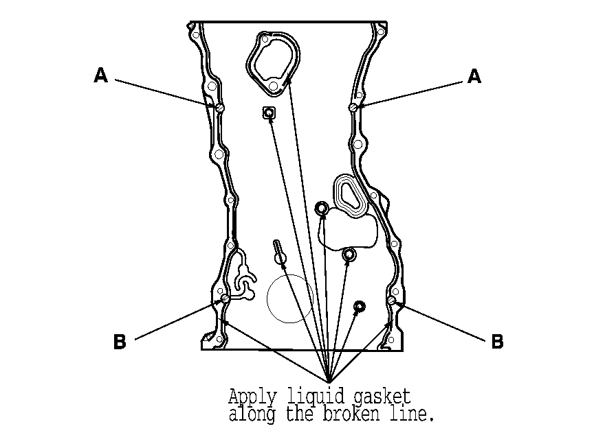
17. Apply liquid gasket to the engine block upper surface contact areas (A) on the chain case and lower block upper surface contact areas (B) on the chain case.
Pic 41
18. Apply liquid gasket, P/N 08717-0004, 08718-0001, 08718-0003, or 08718-0009, evenly to the oil pan mating surface of the chain case, and to the inside edge of the threaded bolt holes. Install the component within 5 minutes of applying the liquid gasket.
NOTE:
- If you apply liquid gasket P/N 08718-0012, the component must be installed within 4 minutes.
- If too much time has passed after applying the liquid gasket, remove the old liquid gasket and residue, then reapply new liquid gasket.
Pic 42
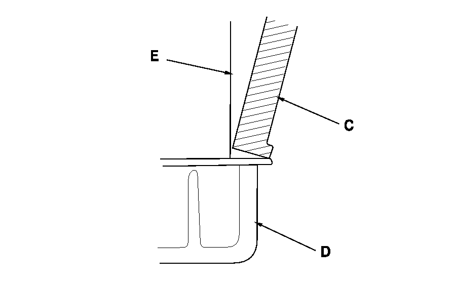
19. Install the spacer (A), then install the new O-ring (B) on the chain case. Set the edge of the chain case (C) to the edge of the oil pan (D), then install the chain case on the engine block (E). Wipe off the excess liquid gasket on the oil pan and chain case mating surface.
NOTE:
- When installing the chain case, do not slide the bottom surface onto the oil pan mounting surface.
- Wait at least 30 minutes before filling the engine with oil.
- Do not run the engine for at least 3 hours after installing the chain case.
Pic 43
Pic 44
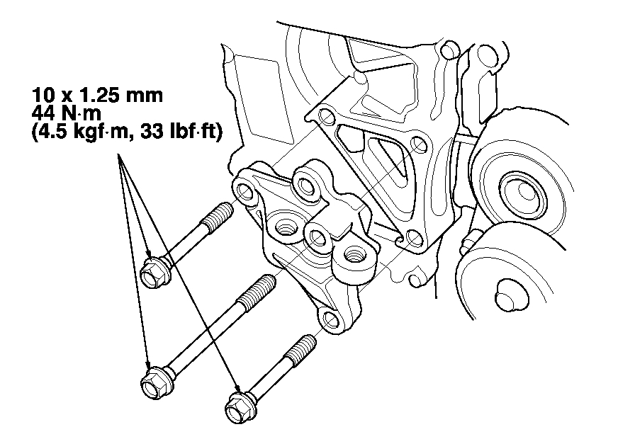
20. Install the side engine mount bracket, then tighten the side engine mount bracket mounting bolts.
Pic 45
21. Tighten the new side engine mount bracket mounting bolts in the numbered sequence shown.
22. Install the ground cable.
23. Remove the jack and the wood block.
24. Install the crankshaft pulley. See: Harmonic Balancer - Crankshaft Pulley > Removal and Replacement > Crankshaft Pulley Removal and Installation (PZEV Model)
25. Install the VTC oil control solenoid valve. See: Variable Valve Timing Actuator > Removal and Replacement > VTC Oil Control Solenoid Valve Removal/Test/Installation
Pic 46
26. Connect the VTC oil control solenoid valve connector (A) and install the harness clamp (B).
27. Install the cylinder head cover. See: Valve Cover > Removal and Replacement > Cylinder Head Cover Installation (PZEV Model)
28. Install the drive belt. See: Drive Belt > Removal and Replacement > Drive Belt Removal/Installation
29. Install the splash shield. See: Engine > Removal and Replacement > Engine Installation
30. Install the front wheels.
31. Do the crankshaft position (CKP) pattern clear/CKP pattern learn procedure. See: Computers and Control Systems > Initial Inspection and Diagnostic Overview
Pic 47
_________________________________
Non PZEV engine
CAM CHAIN INSTALLATION (EXCEPT PZEV MODEL)
Cam Chain Installation
Special Tools Required
- Camshaft lock pin set 07AAB-RWCA120
NOTE:
- Keep the cam chain away from magnetic fields.
- Before doing this procedure, check that the variable valve timing control (VTC) actuator is locked by turning the VTC actuator counterclockwise. If not locked, turn the VTC actuator clockwise until it stops, then recheck it. If it is still not locked, replace the VTC actuator.
1. Set the crankshaft to top dead center (TDC). Align the TDC mark (A) on the crankshaft sprocket with the pointer (B) on the engine block.
Pic 48
2. Set the camshafts to TDC. The punch mark (A) on the VTC actuator and the punch mark (B) on the exhaust camshaft sprocket should be at the top. Align the TDC marks (C) on the VTC actuator and the exhaust camshaft sprocket.
Pic 49
3. To hold the intake camshaft, insert a camshaft lock pin (07AAB-RWCA120) (A) into the maintenance hole in camshaft position (CMP) pulse plate A (B) and through the No. 5 rocker shaft holder (C).
4. To hold the exhaust camshaft, insert a camshaft lock pin (A) into the maintenance hole in CMP pulse plate B (D) and through the No. 5 rocker shaft holder (C).
Pic 50
5. Install the cam chain on the crankshaft sprocket with the colored link plate (A) aligned with the mark (B) on the crankshaft sprocket.
Pic 51
6. Install the cam chain on the VTC actuator and the exhaust camshaft sprocket with the punch marks (A) aligned with the center of the two colored link plates (B).
Pic 52
7. Install cam chain guide A and the tensioner arm (B).
Pic 53
8. Compress the auto-tensioner when replacing the cam chain. Remove the pin from the auto-tensioner. Turn the plate (A) counterclockwise, to release the lock, then press the rod (B), and set the first cam (C) to the first edge of the rack (D). Insert the 1.2 mm (0.05 in.) Diameter pin or lock pin (P/N 14511-PNA-003) (E) into the holes (F).
NOTE: If the chain tensioner is not set up as described, the tensioner will become damaged.
Pic 54
9. Install cam chain guide B.
Pic 55
10. Install the auto-tensioner.
NOTE: Check the auto-tensioner cam position. If the position is not aligned, set the first cam to the first edge of the rack.
Pic 56
11. Remove the pin or lock pin from the auto-tensioner.
Pic 57
12. Remove the camshaft lock pin set.
13. Check the chain case oil seal for damage. If the oil seal is damaged, replace the chain case oil seal. See: Front Crankshaft Seal > Removal and Replacement > Cam Chain Case Oil Seal Installation (Except PZEV Model)
14. Remove the old liquid gasket from the chain case mating surfaces, the bolts, and the bolt holes.
15. Clean and dry the chain case mating surfaces.
Pic 58
16. Apply liquid gasket, P/N 08717-0004, 08718-0001, 08718-0003, or 08718-0009, evenly to the engine block mating surface of the chain case, and to the inside edge of the threaded bolt holes. Install the component within 5 minutes of applying the liquid gasket.
NOTE:
- If you apply liquid gasket P/N 08718-0012, the component must be installed within 4 minutes.
- If too much time has passed after applying the liquid gasket, remove the old liquid gasket and residue, then reapply new liquid gasket.
17. Apply liquid gasket to the engine block upper surface contact areas (A) on the chain case and lower block upper surface contact areas (B) on the chain case.
Pic 59
18. Apply liquid gasket, P/N 08717-0004, 08718-0001, 08718-0003, or 08718-0009, evenly to the oil pan mating surface of the chain case, and to the inside edge of the threaded bolt holes. Install the component within 5 minutes of applying the liquid gasket.
NOTE:
- If you apply liquid gasket P/N 08718-0012, the component must be installed within 4 minutes.
- If too much time has passed after applying the liquid gasket, remove the old liquid gasket and residue, then reapply new liquid gasket.
Pic 60
19. Install the spacer (A), then install the new O-ring (B) on the chain case. Set the edge of the chain case (C) to the edge of the oil pan (D), then install the chain case on the engine block (E). Wipe off the excess liquid gasket on the oil pan and chain case mating surface.
NOTE:
- When installing the chain case, do not slide the bottom surface onto the oil pan mounting surface.
- Wait at least 30 minutes before filling the engine with oil.
- Do not run the engine for at least 3 hours after installing the chain case.
Pic 61
Pic 62
20. Install the side engine mount bracket, then tighten the side engine mount bracket mounting bolts.
Pic 63
21. Tighten the new side engine mount bracket mounting bolts in the numbered sequence shown.
22. Install the ground cable.
23. Remove the jack and the wood block.
24. Install the crankshaft pulley. See: Harmonic Balancer - Crankshaft Pulley > Removal and Replacement > Crankshaft Pulley Removal and Installation (Except PZEV Model)
25. Install the VTC oil control solenoid valve. See: Variable Valve Timing Actuator > Removal and Replacement > VTC Oil Control Solenoid Valve Removal/Test/Installation
Pic 64
26. Connect the VTC oil control solenoid valve connector (A) and install the harness clamp (B).
27. Install the cylinder head cover. See: Valve Cover > Removal and Replacement > Cylinder Head Cover Installation (Except PZEV Model)
28. Install the drive belt. See: Drive Belt > Removal and Replacement > Drive Belt Removal/Installation
29. Install the splash shield. See: Engine > Removal and Replacement > Engine Installation
30. Install the front wheels.
31. Do the crankshaft position (CKP) pattern clear/CKP pattern learn procedure. See: Computers and Control Systems > Initial Inspection and Diagnostic Overview
Pic 65
___________________________________
I know this is extensive, but we need to determine if something was damaged. You have to do one of these to confirm.
Let me know if you have other questions or need help.
Take care,
Joe
Images (Click to make bigger)
SPONSORED LINKS
Monday, September 28th, 2020 AT 12:50 PM