Hi and thanks for using 2CarPros.com.
If you are concerned about timing, honestly the best way is to check the timing chain, but that would require removal of the timing chain covers and inspection. However, if you want, you could do a compression test. If the timing is off, the compression will most likely be low. Here are general directions for checking compression:
https://www.2carpros.com/articles/how-to-test-engine-compression
If you find that one of the three timing chains could be an issue, here are directions for removal and replacement. They are quite extensive, but can be done in the vehicle. The first twenty four pictures correlate with removal of the chains and water pump which I would recommend you do at the same time.
___________________________________________________________
CONVERSION CALCULATOR
1994 Nissan-Datsun Maxima V6-2960cc 3.0L DOHC (VE30DE)
Vehicle � Engine, Cooling and Exhaust � Engine � Timing Chain � Service and Repair � Removal
REMOVAL
POSITION FOR APPLYING LIQUID GASKET
CAUTION:
After removing timing chain, do not turn crankshaft and camshaft separately, or valves will strike piston heads.
When installing sliding parts such as rocker arms, camshafts, chain tensioner and oil seal, be sure to apply new engine oil on their sliding surfaces.
When tightening cylinder head bolts, intake camshaft sprocket bolts, crankshaft pulley bolt, camshaft bracket bolts, idler sprocket bolts and chain guide bolts, apply new engine oil to thread portions and seat surfaces of bolts.
REMOVAL
Release fuel pressure.
Remove engine under covers.
Remove front R.H. wheel and engine side cover.
Drain coolant by removing cylinder block drain plugs and radiator drain cock.
Remove radiator.
Remove air duct to intake manifold, blow-by pipe, vacuum hoses, fuel hoses, wires, harness, connectors and so on.
Remove E.G.R. tube.
Remove R.H. ignition coils.
Remove intake manifold collector supports.
Remove the following hoses:
Vacuum hose for pressure regulator
Water hoses for throttle body
Air hose for IACV-AAC valve
Canister purge hose
Blow-by hose
Remove intake manifold collector in reverse order of installation.
Remove L.H. ignition coils.
Remove all spark plugs.
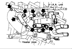
Remove I.A.A. unit and heater pipe.
Remove injector tube assembly.
Remove R.H. V.T.C. solenoid valve.
Remove intake manifold in reverse order of installation.
Remove drive belts.
Remove compressor and alternator.
Remove compressor & alternator bracket.
Remove idler pulley bracket.
Remove oil level gauge guide support.
Remove L.H. exhaust manifold in reverse order of installation.
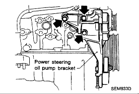
Remove power steering oil pump and its bracket.
Remove R.H. exhaust manifold in reverse order of installation.
Remove R.H. and L.H. rocker covers.
Remove R.H. and L.H. upper chain guides.
Remove R.H. and L.H. upper front covers.
Set No.1 piston at T.D.C. on the compression stroke by rotating crankshaft.
Rotate crankshaft until mating marks on camshaft sprockets are set in correct position.
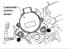
Remove crankshaft position sensor.
Remove R.H. and L.H. chain tensioners.
Remove camshaft sprockets and V.T.C. assemblies.
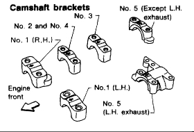
Remove R.H. exhaust camshaft, camshaft brackets and rocker arms.
Remove L.H. exhaust camshaft, camshaft brackets and rocker arms.
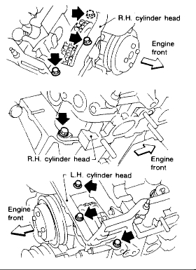
Remove cylinder head outside bolts.
Remove cylinder heads.
Cylinder head bolts should be loosened in two or three steps.
A warped or cracked cylinder head could result from removing in incorrect order.
Remove water pipe.
Remove water pump pulley and water pump.
Remove oil pan.
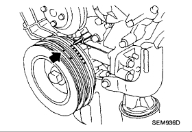
Remove crankshaft pulley.
Remove oil strainer.
Remove oil filter bracket.
Remove front cover, alternator adjusting bar and upper timing chains.
Remove chair tensioner
Remove chain guides.
Remove idler sprockets and lower timing chain.
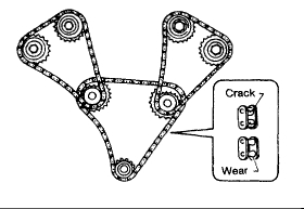
Note: Check for cracks and excessive wear at roller links. Replace chain if necessary.
____________________________________________________________________________
Here are the directions for replacement. The remaining pictures correlate with these directions.
1994 Nissan-Datsun Maxima V6-2960cc 3.0L DOHC (VE30DE)
Vehicle � Engine, Cooling and Exhaust � Engine � Timing Chain � Service and Repair � Installation
INSTALLATION
Install crankshaft sprocket on crankshaft.
Position crankshaft so that No.1 piston is set at T.D.C. on compression stroke.
Install R.H. idler sprocket and chain guides.
Position lower timing chain on R.H. idler sprocket by aligning the mating mark on the R.H. idler sprocket with the silver mating mark on the lower timing chain.
Install L.H. idler sprocket with lower timing chain.
Line up mating marks on lower timing chain with mating marks on L.H. idler sprocket and crankshaft sprocket.
Install chain guide and chain tensioner.
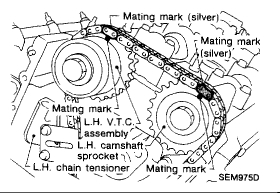
Position upper timing chains on idler sprockets by aligning the mating marks on the idler sprockets with the gold mating marks on the upper timing chains.
Install oil pump drive spacer, front cover and alternator adjusting bar.
Before installing front cover, remove all traces of liquid gasket from mating surface and grooves using a scraper and then completely clean any oil stains.
Also remove traces of liquid gasket from mating surface of cylinder block.
Apply a continuous bead of liquid gasket to mating surface of front cover.
Use Genuine Liquid Gasket or equivalent.
Wipe off excessive liquid gasket.
Install oil filter bracket.
Install oil strainer.
Install crankshaft pulley.
Set No.1 piston at T.D.C. on its compression stroke.
Install oil pan.
Install water pump.
Before installing water pump, remove all traces of liquid gasket from mating surface and groove using a scraper.
Also remove traces of liquid gasket from mating surface of front cover and water pipe.
Apply a continuous bead of liquid gasket to mating surface of water pump.
Use Genuine Liquid Gasket or equivalent.
Install water pump pulley.
Install water pipe.
Turn crankshaft until No.1 piston is set at approximately 120° before T.D.C. on compression stroke to prevent interference of valves and pistons.
Install cylinder heads with new gaskets.
Before installing cylinder head gaskets, apply a continuous bead of liquid gasket to mating surface of cylinder block.
Be sure to install washers between bolts and cylinder head.
Do not rotate crankshaft and camshaft separately, or valves will strike piston heads.
Tightening procedure:
Tighten all bolts to 39 Nm (4.0 kg-m, 29 ft-lb) .
Bolts of A type: Turn A bolts 65 to 70 degrees clockwise with Tool or suitable angle wrench.
Bolts of B type: Turn B bolts 70 to 75 degrees clockwise with Tool or suitable angle wrench. If angle wrench is not available, tighten all bolts to 123 Nm (12.5 kg-m, 90 ft-lb)
Loosen all bolts completely.
Tighten all bolts to 34 to 44 Nm (3.5 to 4.5 kg-m, 25 to 33 ft-lb) .
Bolts of A type: Turn A bolts 65 to 70 degrees clockwise with Tool or suitable angle wrench.
Bolts of B type: Turn B bolts 70 to 75 degrees clockwise with Tool or suitable angle wrench.
If angle wrench Is not available, tighten all bolts to 118 to 127 Nm (12.0 to 13.0 kg-m, 87 to 94 ft-lb).
Install cylinder head outside bolts.
Install exhaust camshafts, camshaft brackets and rocker arms.
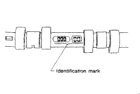
Install exhaust camshafts, noting their identification marks.
Position camshaft R.H. exhaust camshaft key at about 10 o'clock
L.H. exhaust camshaft key at about 12 o'clock
Install camshaft brackets in their original positions.
Before installing L.H. exhaust camshaft end bracket, remove all traces of liquid gasket from mating surface, and then completely clean any oil stains.
Also remove traces of liquid gasket from mating surface of cylinder head.
Apply a continuous bead of liquid gasket to mating surface of L.H. exhaust camshaft end bracket.
Use Genuine Liquid Gasket or equivalent.
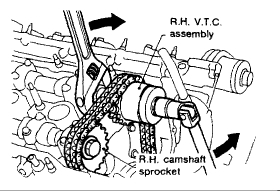
Install R.H. V.T.C. assembly.
Install R.H. camshaft sprocket.
Line up mating marks on R.H. upper timing chain with mating marks on R.H. V.T.C. assembly and R.H. camshaft sprocket.
Install R.H. chain tensioner.
Before installing chain tensioner, press-in sleeve until hook can be engaged on pin. Make sure that hook used to retain chain tensioner is released.
There are two types of chain tensioner. Be careful not to install L.H. chain tensioner onto R.H cylinder head.
Turn crankshaft clockwise to set No.1 piston at T.D.C. compression stroke.
Install L.H. V.T.C. assembly
Install: L.H. camshaft sprocket.
Line up mating marks on L.H. upper timing chain with mating marks on L.H. V.T.C. assembly and L.H. camshaft sprocket.
Install L.H. chain tensioner
Make sure that upper timing chains are in the correct position.
Install crankshaft position sensors.
Make sure that position of camshaft and rotor position of crank shaft position sensor are as shown.
Install R.H. and L.H. upper front covers.
Before installing R.H. and L.H. upper front covers, remove all traces of liquid gasket from mating surface and groove using a scraper, and completely clean any oil stains.
Also remove traces of liquid gasket from mating surface of cylinder head.
Apply a continuous bead of liquid gasket to mating surface of R.H. and L.H. upper front covers.
Use Genuine Liquid Gasket or equivalent.
Install R.H and L.H. upper chain guides.
Install R.H. and L.H. rocker covers.
Before installing rocker covers, remove all traces of liquid gasket from mating surface of rocker cover to cylinder head, and then completely clean any oil stains.
Apply a continuous bead of liquid gasket to mating surface of rocker cover gaskets and cylinder heads.
Use Genuine Liquid Gasket or equivalent.
Rocker cover tightening procedure.
1 Tighten nuts 1-2-12-11-9-14 in that order to 4 Nm (0.4 kg-m, 2.9 ft-lb)
2 Tighten nuts 1 to 14 as indicated in image to 8 to 10 Nm (0.8 to 1.0 kg-m, 5.8 to 7.2 ft-lb).
Reinstall any parts removed in reverse order of removal
When installing injector tube assembly refer to "Injector Removal and Installation.
When installing V.T.C. solenoid valve, always use new O-rings, and apply engine oil to new O-rings.
_________________________________________________________________
Please keep in mind, the directions also include replacing head gaskets which you will not be doing.
I hope this helps. I realize it is extensive, but if you find a chain has jumped, I figured I would give you the directions.
Take care and let me know if you have questions,
Joe
Images (Click to make bigger)
SPONSORED LINKS
Tuesday, June 12th, 2018 AT 8:21 PM