Welcome back:
That will do it. What to do is flush the cooling system. Take out the thermostat and radiator hoses. Flush it with pressure from a hose. If there is anything in there, it should come out.
https://www.2carpros.com/articles/coolant-flush-and-refill-all-cars
Here are the directions for pump replacement. I have to break it down by components. The timing belt needs removed, so this is a great time to replace the belt and tensioner. All pics will correlate with the directions. Removal and install of the timing belt is second. If you need anything as far as component removal, let me know.
__________________________________________
Change Vehicle Technician's Reference
water pump
1999 Lexus Truck RX 300 FWD V6-3.0L (1MZ-FE)
Procedures
Vehicle Engine, Cooling and Exhaust Engine Water Pump Service and Repair Procedures
PROCEDURES
pic 1
pic 2
pic 3
pic 4
REMOVAL
1. DRAIN ENGINE COOLANT
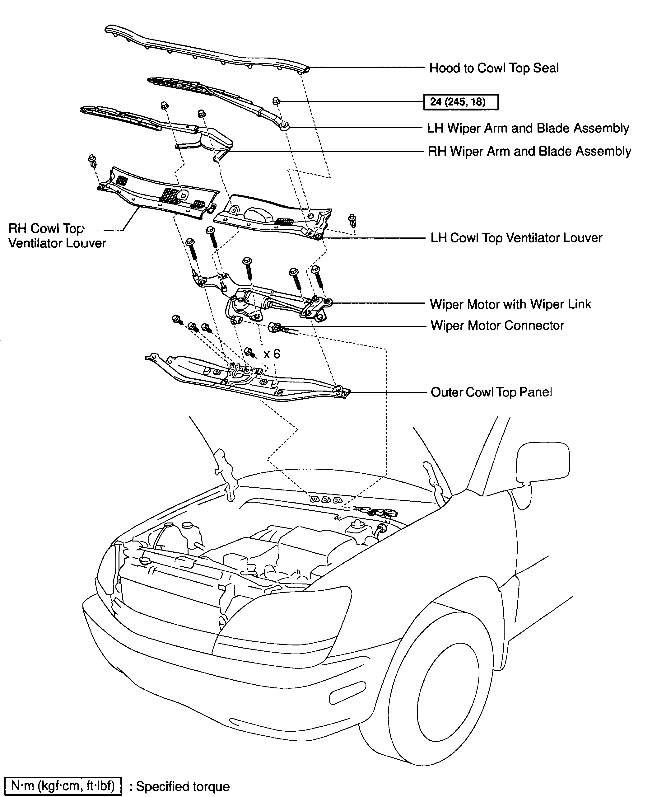
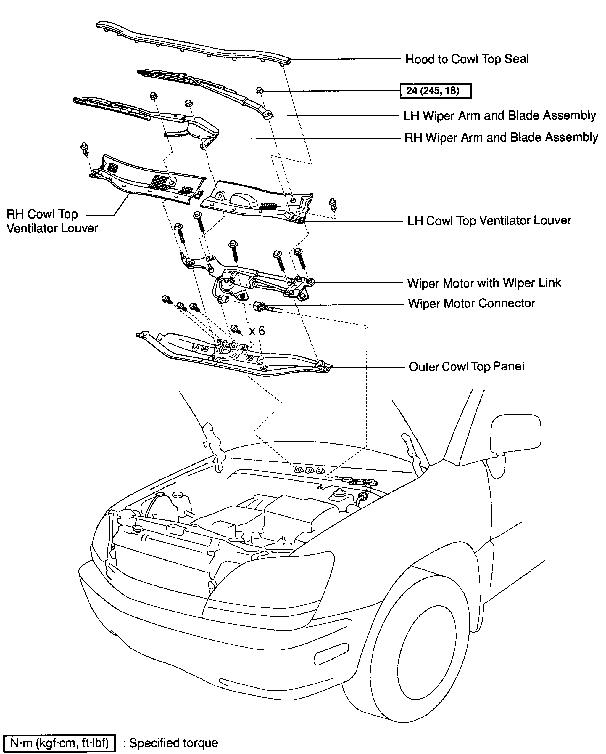
2. REMOVE OUTER COWL TOP PANEL
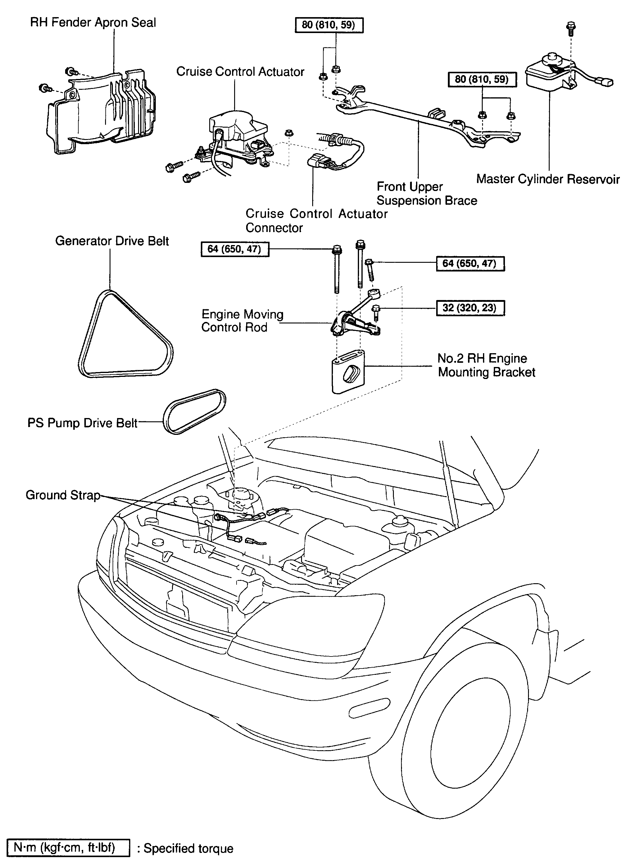
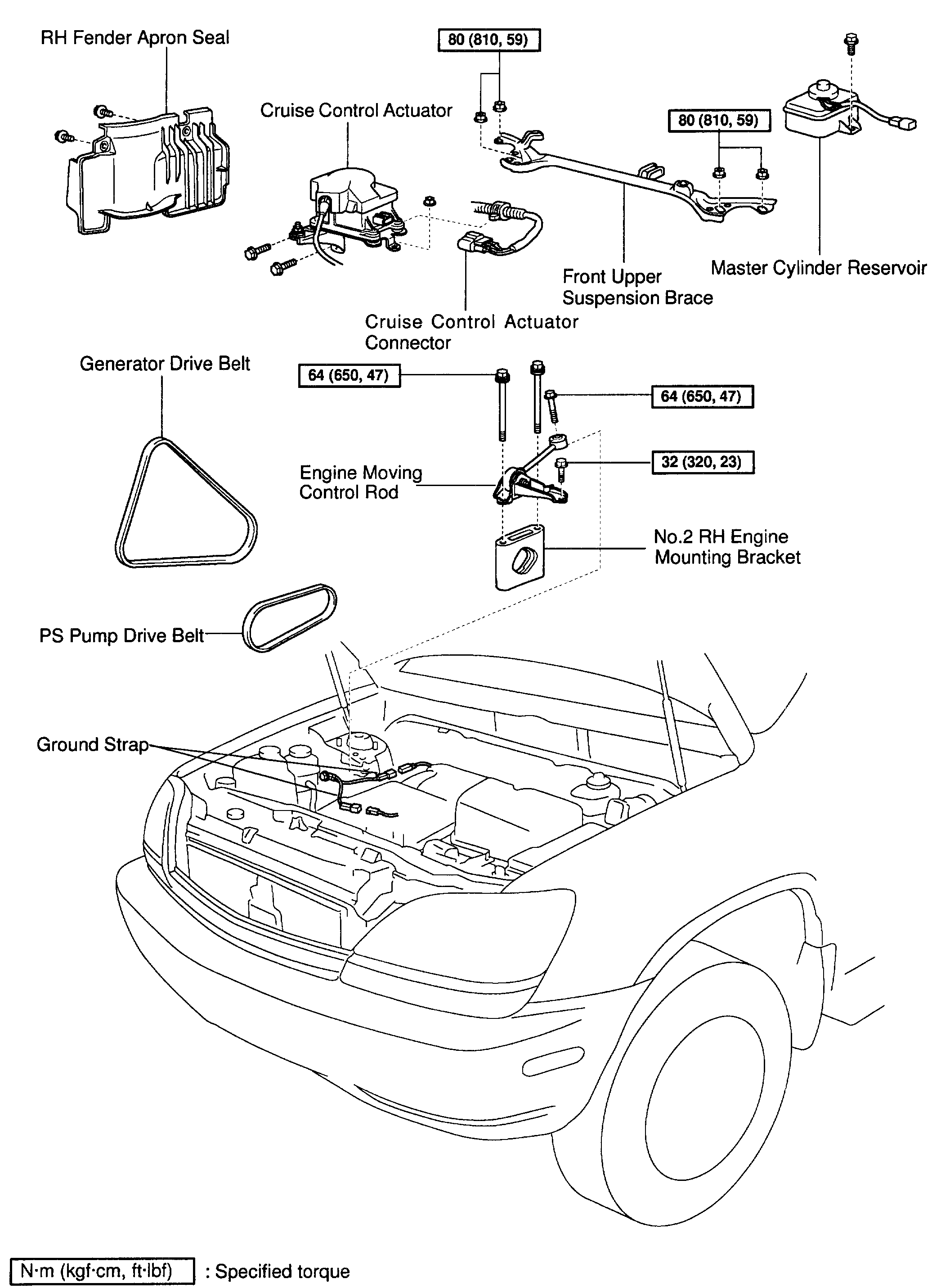
3. REMOVE FRONT UPPER SUSPENSION BRACE
4. REMOVE TIMING BELT
5. REMOVE CAMSHAFT TIMING PULLEYS
6. REMOVE NO.2 IDLER PULLEY
7. REMOVE NO.3 TIMING BELT COVER
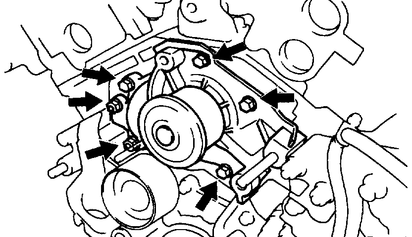
8. REMOVE WATER PUMP
pic 5
Remove the 4 bolts, 2 nuts, water pump and gasket.
INSPECTION
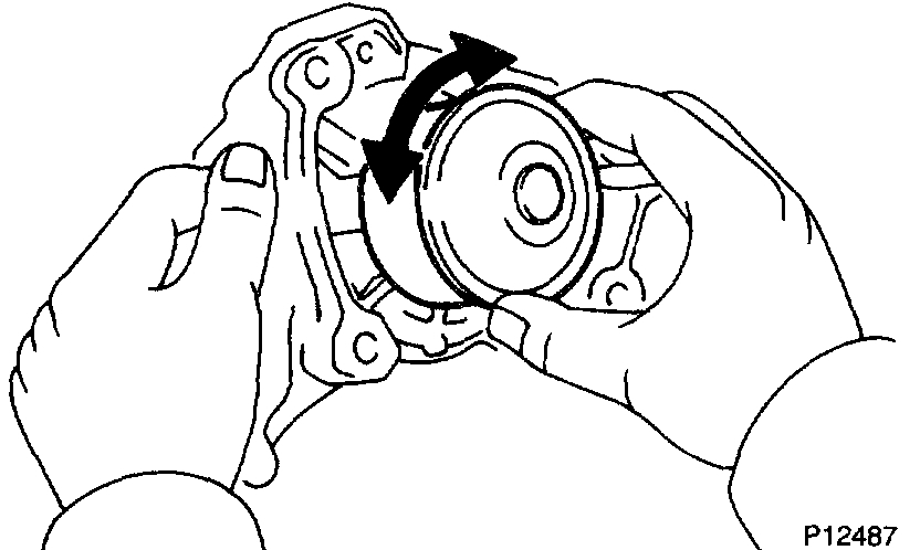
1. INSPECT WATER PUMP
a. Visually check the drain hole for coolant leakage.
If leakage is found, replace the water pump.
pic 6
b. Turn the pulley, and check that the water pump bearing moves smoothly and quietly.
If necessary, replace the water pump.
2. INSPECT TIMING BELT COMPONENTS
INSTALLATION
1. INSTALL WATER PUMP
pic 7
Install a new gasket and the water pump with the 4 bolts and 2 nuts.
Torque: 6 Nm (60 kgf-cm, 53 inch lbs.)
NOTICE: Do not get oil on the gasket.
2. INSTALL NO.3 TIMING BELT COVER
3. INSTALL NO.2 IDLER PULLEY
4. INSTALL CAMSHAFT TIMING PULLEYS
5. INSTALL TIMING BELT
6. INSTALL FRONT UPPER SUSPENSION BRACE
7. INSTALL OUTER COWL TOP PANEL
8. FILL WITH ENGINE COOLANT
9. START ENGINE AND CHECK FOR LEAKS
10. RECHECK ENGINE COOLANT LEVEL
_____________________________
1999 Lexus Truck RX 300 FWD V6-3.0L (1MZ-FE)
Removal and Replacement
Vehicle Engine, Cooling and Exhaust Engine Timing Components Timing Belt Service and
REMOVAL AND REPLACEMENT
pic 8
pic 9
pic 10
REMOVAL
1. REMOVE OUTER COWL TOP PANEL
2. REMOVE FRONT UPPER SUSPENSION BRACE
3. REMOVE RH FRONT WHEEL
4. REMOVE RH FENDER APRON SEAL
5. REMOVE GENERATOR DRIVE BELT
6. REMOVE PS PUMP DRIVE BELT
pic 11
Loosen the 2 bolts, and remove the drive belt.
7. REMOVE CRUISE CONTROL ACTUATOR
8. DISCONNECT GROUND STRAP CONNECTORS
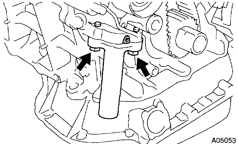
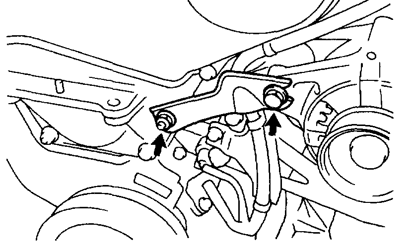
9. REMOVE ENGINE MOVING CONTROL ROD AND NO.2 RH ENGINE MOUNTING BRACKET
10. REMOVE NO.2 GENERATOR BRACKET
pic 12
a. Loosen the generator pivot bolt.
b. Remove the nut and bracket.
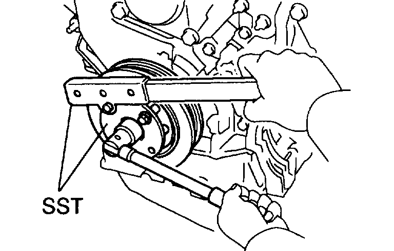
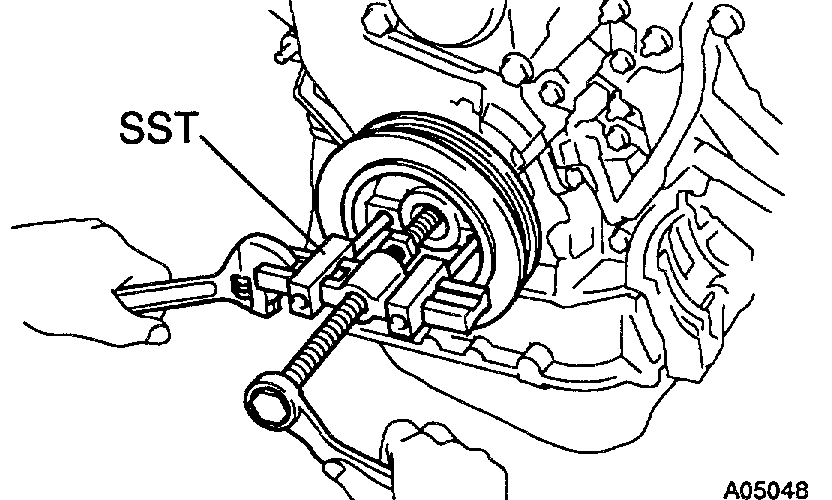
11. REMOVE CRANKSHAFT PULLEY
pic 13
a. Using Special Service Tool (SST), remove the pulley bolt.
SST 09213-54015 (91651-60855), 09330-00021
pic 14
b. Using SST, remove the pulley.
SST 09950-50010 (09951-05010, 09952-05010, 09953-05010, 09953-05020, 09954-05020)
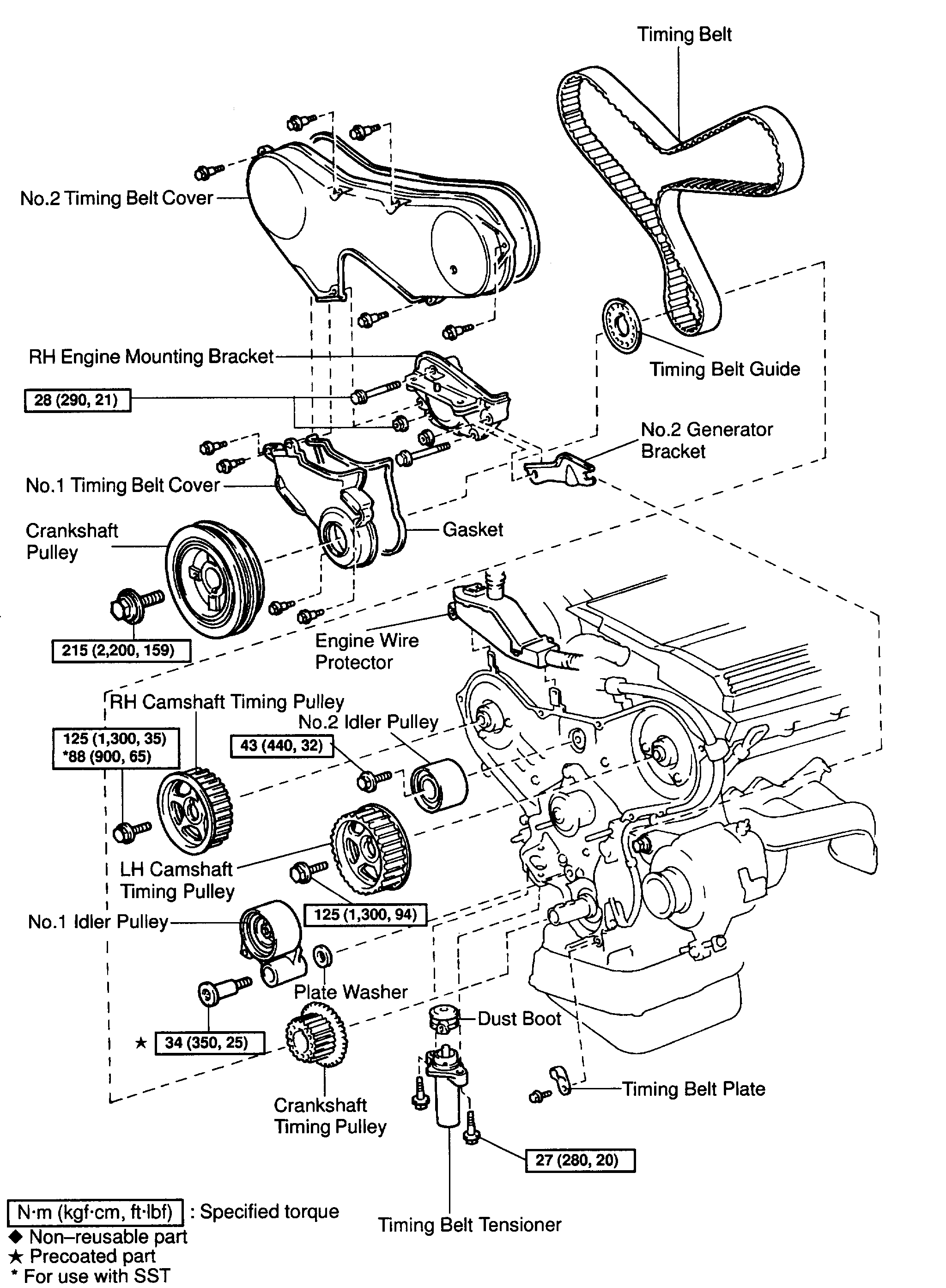
12. REMOVE NO.1 TIMING BELT COVER
pic 15
Remove the 4 bolts and timing belt cover.
13. REMOVE TIMING BELT GUIDE
14. REMOVE NO.2 TIMING BELT COVER
pic 16
a. Disconnect the engine wire protector clamps from the No.3 timing belt cover.
b. Remove the 5 bolts and timing belt cover.
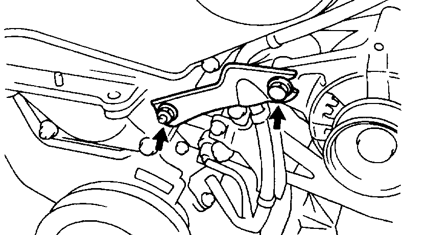
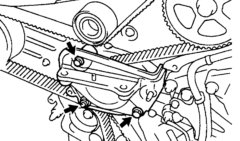
15. REMOVE RH ENGINE MOUNTING BRACKET
pic 17
Remove the 2 bolts, nut and mounting bracket.
16. SET NO.1 CYLINDER TO TDC/COMPRESSION
a. Temporarily install the crankshaft pulley bolt to the crankshaft.
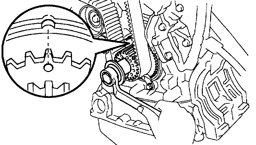
pic 18
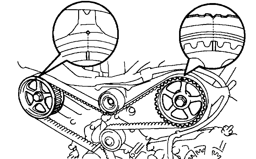
b. Turn the crankshaft, and align the timing marks of the crankshaft timing pulley and oil pump body.
NOTICE: Always turn the crankshaft clockwise.
pic 19
c. Check that timing marks of the camshaft timing pulleys and No.3 timing belt cover are aligned.
If not, turn the crankshaft 1 revolution (360°).
d. Remove the crankshaft pulley bolt.
17. IF REUSING TIMING BELT, CHECK INSTALLATION MARKS ON TIMING BELT
pic 20
Check that there are 3 installation marks and front mark on the timing belt. If the installation and front marks have disappeared, before removing the timing belt, place 3 new installation marks on the timing belt to match the timing marks of the timing pulleys, and place a new front mark on the timing belt.
18. REMOVE TIMING BELT TENSIONER
pic 21
Alternately loosen the 2 bolts, and remove them, the tensioner and dust boot.
19. REMOVE TIMING BELT
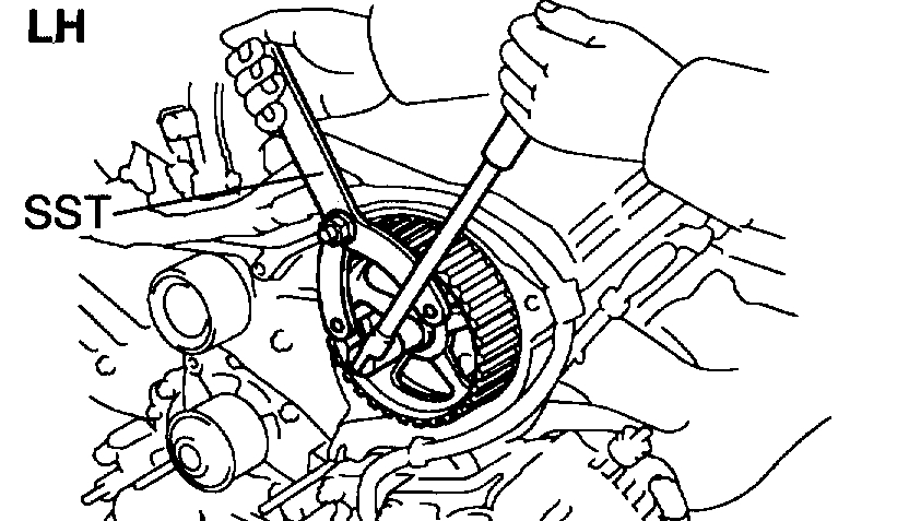
20. REMOVE CAMSHAFT TIMING PULLEYS
pic 22
a. Using SST, remove the bolt and RH timing pulley.
SST 09249-63010, 09960-10010 (09962-01000, 09963-01000)
pic 23
b. Using SST, remove the LH timing pulley.
SST 09960-10010 (09962-01000, 09963-01000)
HINT: Arrange the camshaft timing pulleys (RH and LH sides).
21. REMOVE NO.2 IDLER PULLEY
pic 24
Remove the bolt and idler pulley.
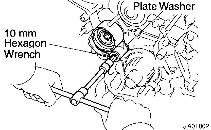
22. REMOVE NO.1 IDLER PULLEY
pic 25
Using a 10 mm hexagon wrench, remove the bolt, idler pulley and plate washer.
23. REMOVE CRANKSHAFT TIMING PULLEY
a. Remove the bolt and timing belt plate.
pic 26
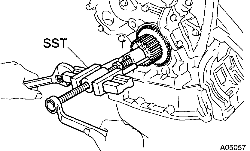
b. Using SST, remove the crankshaft timing pulley.
SST 09950-50010 (09951-05010, 09952-05010, 09953-05010, 09953-05020, 09954-05010)
NOTICE: Do not scratch the sensor part of the crankshaft timing pulley.
INSPECTION
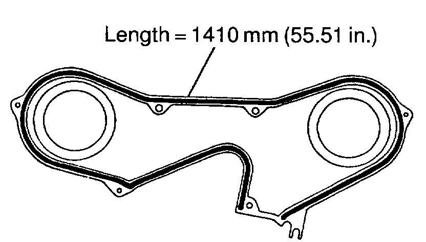
1. INSPECT TIMING BELT
pic 27
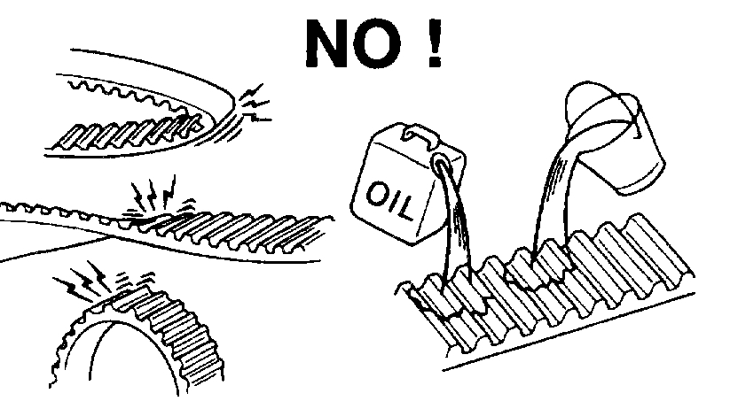
NOTICE:
- Do not bend, twist or turn the timing belt inside out.
- Do not allow the timing belt to come into contact with oil, water or steam.
- Do not utilize timing belt tension when installing or removing the mount bolt of the camshaft timing pulley.
If there are any defects, as shown in the illustrations, check these points:
a. Premature parting
- Check for proper installation.
- Check the timing cover gasket for damage and proper installation.
b. If the belt teeth are cracked or damaged, check to see if either camshaft is locked.
c. If there is noticeable wear or cracks on the belt face, check to see if there are nicks on the side of the idler pulley lock and water pump.
d. If there is wear or damage on only one side of the belt, check the belt guide and the alignment of each pulley.
e. If there is noticeable wear on the belt teeth, check timing cover for damage and check gasket has been installed correctly and check for foreign material on the pulley teeth.
If necessary, replace the timing belt.
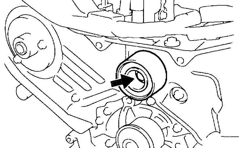
2. INSPECT IDLER PULLEYS
pic 28
a. Visually check the seal portion of the idler pulley for oil leakage.
If leakage is found, replace the idler pulley.
pic 29
b. Check that the idler pulley turns smoothly.
If necessary, replace the idler pulley.
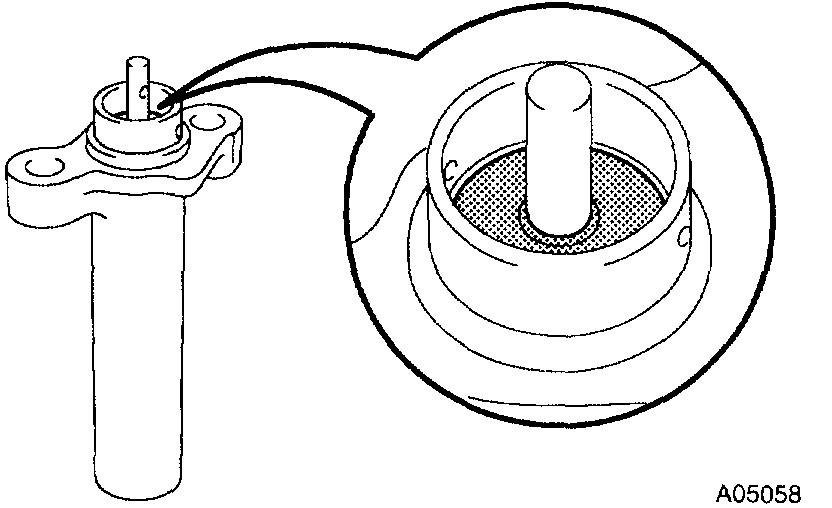
3. INSPECT TIMING BELT TENSIONER
pic 30
a. Visually check the seal portion of the tensioner for oil leakage.
HINT: If there is only the faintest trace of oil on the seal on the push rod side, the tensioner is all right.
If leakage is found, replace the tensioner.
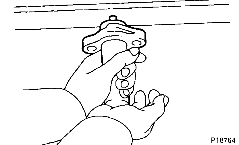
pic 31
b. Hold the tensioner with both hands and push the push rod strongly as shown to check that it doesn't move.
If the push rod moves, replace the tensioner.
NOTICE: Never hold the tensioner push rod facing downward.
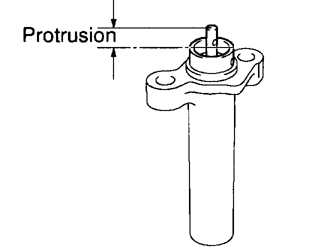
pic 32
c. Measure the protrusion of the push rod from the housing end.
Protrusion: 10.0 - 10.8 mm (0.394 - 0.425 inch)
If the protrusion is not as specified, replace the tensioner.
INSTALLATION
1. INSTALL CRANKSHAFT TIMING PULLEY
a. Align the pulley set key with the key groove of the timing pulley, and slide on the timing pulley.
pic 33
b. Install the timing pulley, facing the sensor side inward.
NOTICE: Do not scratch the sensor part of the crankshaft timing pulley.
c. Install the timing belt plate with the bolt.
Torque: 8 Nm (80 kgf-cm, 69 inch lbs.)
2. INSTALL NO.1 IDLER PULLEY
Adhesive: Part No. 08833-00080, THREE BOND 1344, LOCTITE 242 or equivalent
pic 34
a. Using a 10 mm hexagon wrench, install the plate washer and idler pulley with the pivot bolt.
Torque: 34 Nm (350 kgf-cm, 25 ft. lbs.)
b. Check that the pulley bracket moves smoothly.
3. INSTALL NO.2 IDLER PULLEY
pic 35
a. Install the idler pulley with the bolt.
Torque: 43 Nm (440 kgf-cm, 32 ft. lbs.)
b. Check that the idler pulley moves smoothly.
4. INSTALL RH CAMSHAFT TIMING PULLEY
a. Face the flange side of the timing pulley outward.
b. Align the knock pin on the camshaft with the knock pin groove of the timing pulley, and slide on the timing pulley.
pic 36
c. Using Special Service Tool (SST), install the pulley bolt.
SST 09249-63010, 09960-10010 (09962-01000, 09963-01000)
Torque: 88 Nm (900 kgf-cm, 65 ft. lbs.)
HINT: Use a torque wrench with a fulcrum length of 340 mm (13.39 inch).
5. INSTALL LH CAMSHAFT TIMING PULLEY
a. Face the flange side of the timing pulley inward.
b. Align the knock pin on the camshaft with the knock pin groove of the timing pulley, and slide on the timing pulley.
pic 37
c. Using SST, install the pulley bolt.
SST 09960-10010 (09962-01000, 09963-01000)
Torque: 125 Nm (1,300 kgf-cm, 94 ft. lbs.)
6. SET NO.1 CYLINDER TO TDC/COMPRESSION
pic 38
a. Crankshaft Timing Pulley Position:
Temporarily install the crankshaft pulley bolt to the crankshaft.
b. Crankshaft Timing Pulley Position:
Turn the crankshaft, and align the timing marks of the crankshaft timing pulley and oil pump body.
pic 39
c. Camshaft Timing Pulley Positions:
Using SST, turn the camshaft pulley, align the timing marks of the timing pulley and No.3 timing belt cover.
SST 09960-10010 (09962-01000, 09963-01000)
7. INSTALL TIMING BELT
NOTICE: The engine should be cold.
a. Remove any oil or water on the pulleys, and keep them clean.
NOTICE: Only wipe the pulleys; do not use any cleansing agent.
b. Face the front mark on the timing belt forward.
c. Align the installation mark on the timing belt with the timing mark of the crankshaft timing pulley.
d. Align the installation marks on the timing belt with the timing marks of the camshaft timing pulleys.
pic 40
e. Install the timing belt in this order:
1st: Crankshaft timing pulley
2nd: Water pump pulley
3rd: LH camshaft timing pulley
4th: No.2 idler pulley
5th: RH camshaft timing pulley
6th: No.1 idler pulley
8. SET TIMING BELT TENSIONER
a. Using a press, slowly press in the push rod using 981 - 9,807 N (100 - 1,000 kgf, 200 - 2,205 lbs.) of pressure.
pic 41
b. Align the holes of the push rod and housing, pass a 1.27 mm hexagon wrench through the holes to keep the setting position of the push rod.
c. Release the press.
pic 42
d. Install the dust boot to the tensioner.
9. INSTALL TIMING BELT TENSIONER
a. Temporarily install the tensioner with the 2 bolts.
b. Alternately tighten the 2 bolts.
Torque: 27 Nm (280 kgf-cm, 20 ft. lbs.)
pic 43
c. Remove the 1.27 mm hexagon wrench from the tensioner.
10. CHECK VALVE TIMING
pic 44
a. Slowly turn the crankshaft 2 revolutions, and align the timing marks of the crankshaft timing pulley and oil pump body.
NOTICE: Always turn the crankshaft clockwise.
pic 45
b. Check that the timing marks of the RH and LH timing pulleys with the timing marks of the No.3 timing belt cover as shown in the illustration.
If the marks do not align, remove the timing belt and reinstall it.
c. Remove the crankshaft pulley bolt.
11. INSTALL RH ENGINE MOUNTING BRACKET
Torque: 28 Nm (290 kgf-cm, 21 ft. lbs.)
12. INSTALL NO.2 TIMING BELT COVER
a. Check that the timing belt cover gasket has no cracks or peeling, etc.
If the gasket has cracks or peeling, etc., replace it using these steps:
- Using a screwdriver and gasket scraper, remove all the old gasket material.
- Thoroughly clean all components to remove all the loose material.
pic 46
- Remove the backing paper from a new gasket and install the gasket evenly to the part of the timing belt cover shaded black in the illustration.
- After installing the gasket, press down on it so that the adhesive firmly sticks to the timing belt cover.
b. Install the timing belt cover with the 5 bolts.
Torque: 8.5 Nm (85 kgf-cm, 74 inch lbs.)
c. Install the engine wire protector clamps to the No.3 timing belt cover.
13. INSTALL TIMING BELT GUIDE
pic 47
Install the timing belt guide, facing the cup side outward.
14. INSTALL NO.1 TIMING BELT COVER
a. Check that the timing belt cover gaskets have cracks or peeling, etc.
If the gasket has cracks or peeling, etc., replace it using these steps:
- Using a screwdriver and gasket scraper, remove all the old gasket material.
- Thoroughly clean all components to remove all the loose material.
Pic 48
- Remove the backing paper from a new gasket and install the gasket evenly to the part of the timing belt cover shaded black in the illustration.
NOTICE: When joining 2 gaskets, do not leave a gap between them. Cut off any excess gasket.
- After installing the gasket, press down on it so that the adhesive firmly sticks to the timing belt cover.
b. Install the timing belt cover with the 4 bolts.
Torque: 8.5 Nm (85 kgf-cm, 74 inch lbs.)
15. INSTALL CRANKSHAFT PULLEY
a. Align the pulley set key with the key groove of the pulley, and slide on the pulley.
Pic 49
b. Using SST, install the pulley bolt.
SST 09213-54015 (91651-60855), 09330-00021
Torque: 215 Nm (2,200 kgf-cm, 159 ft. lbs.)
16. INSTALL NO.2 GENERATOR BRACKET
pic 50
Install the generator bracket with the pivot bolt and nut. Do not tighten the bolt yet.
Torque: (Nut): 28 Nm (290 kgf-cm, 21 ft. lbs.)
17. INSTALL NO.2 RH ENGINE MOUNTING BRACKET AND ENGINE MOVING CONTROL ROD
18. CONNECT GROUND STRAP CONNECTORS
19. INSTALL CRUISE CONTROL ACTUATOR
20. INSTALL PS PUMP DRIVE BELT
21. INSTALL GENERATOR DRIVE BELT
22. INSTALL RH FENDER APRON SEAL
23. INSTALL RH FRONT WHEEL
24. INSTALL FRONT UPPER SUSPENSION BRACE
25. INSTALL OUTER COWL TOP PANEL
26. VEHICLE ROAD TEST
Check for abnormal noise, shock, slippage, correct shift points and smoothly operation.
_____________________________________________
I hope this helps. Please let me know if I can help.
Images (Click to make bigger)
Thursday, August 15th, 2019 AT 6:37 PM