Based on the code, it isn't related to the parts but rather the CAN bus. The modules are unable to communicate with each other. Take a look through this and let me know if it helps. Also, the attached pic correlates with the directions.
________________________________
2006 Nissan-Datsun Truck Murano FWD V6-3.5L (VQ35DE)
CAN Communication
Vehicle ALL Diagnostic Trouble Codes ( DTC ) Testing and Inspection U Code Charts U1001 CAN Communication
CAN COMMUNICATION
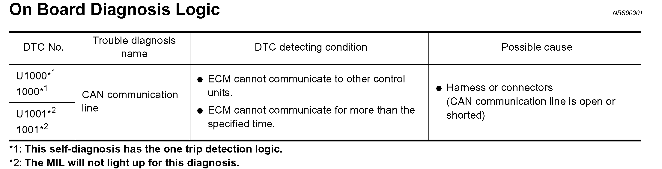
DTC U1000, U1001 CAN COMMUNICATION LINE
Description
CAN (Controller Area Network) is a serial communication line for real time application. It is an on-vehicle multiplex communication line with high data communication speed and excellent error detection ability. Many electronic control units are equipped onto a vehicle, and each control unit shares information and links with other control units during operation (not independent). In CAN communication, control units are connected with 2 communication lines (CAN H line, CAN L line) allowing a high rate of information transmission with less wiring. Each control unit transmits/receives data but selectively reads required data only.
Pic 1
On Board Diagnosis Logic
DTC Confirmation Procedure
1. Turn ignition switch ON and wait at least 3 seconds.
2. Select "DATA MONITOR" mode with CONSULT-II.
3. If 1st trip DTC is detected, go to "Diagnostic Procedure" below.
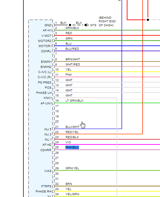
EC-CAN-01
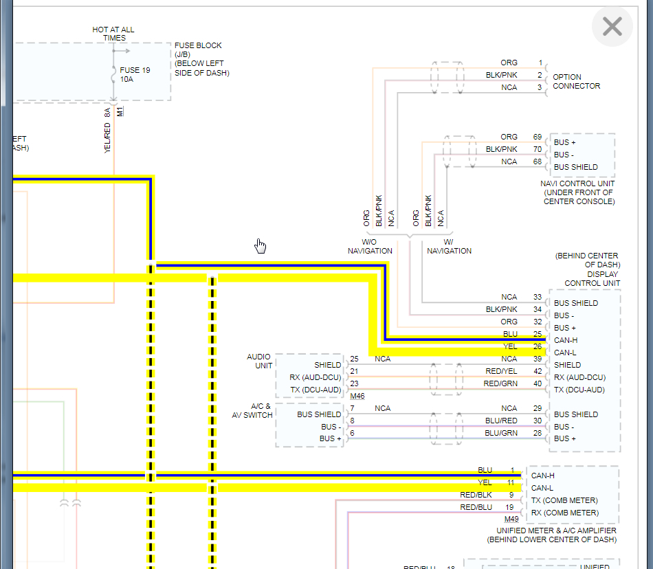
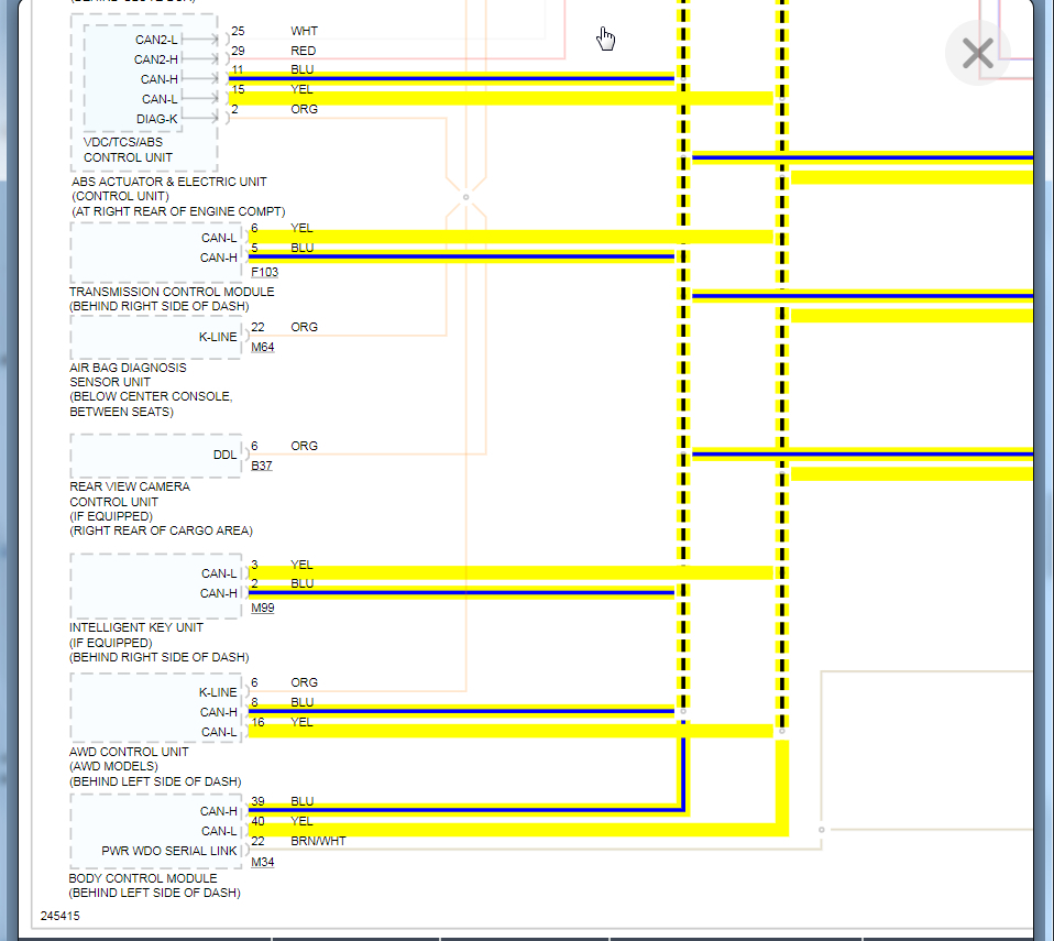
pic 2
Wiring Diagram
Diagnostic Procedure
Go to LAN-3, "Precautions When Using CONSULT-II". See: Information Bus > Vehicle Damage Warnings > Precautions When Using CONSULT-II
Let me know if this helps.
Joe
Images (Click to make bigger)
SPONSORED LINKS
Wednesday, January 20th, 2021 AT 5:34 PM