Zero point calibration

Tiny
CGOETZ1984
  • MEMBER
  • 2004 TOYOTA 4RUNNER
  • 4.7L
  • V8
  • 4WD
  • AUTOMATIC
  • 248,000 MILES
I'm trying to figure out which terminals I need to connect a wire to to do a zero point calibration are my vehicle listed above. Any help would be greatly appreciated. Thanks in advance.
Thursday, November 5th, 2020 AT 5:57 AM

12 Replies

Tiny
ASEMASTER6371
  • MECHANIC
  • 52,797 POSTS
Good morning,

Please explain 0 point calibration.

Roy
Was this
answer
helpful?
Yes
No
Thursday, November 5th, 2020 AT 6:05 AM
Tiny
CGOETZ1984
  • MEMBER
  • 16 POSTS
I was reading online that you can use the OBD2 sensor port to perform it.
Was this
answer
helpful?
Yes
No
Thursday, November 5th, 2020 AT 6:22 AM
Tiny
CGOETZ1984
  • MEMBER
  • 16 POSTS
My traction lights are on.
Was this
answer
helpful?
Yes
No
-1
Thursday, November 5th, 2020 AT 6:22 AM
Tiny
ASEMASTER6371
  • MECHANIC
  • 52,797 POSTS
Okay, thank you.

There is a fault code set in the ABS system. I need that code to determine the possible failures.

The traction control light is part of the ABS system and works through the ABS module.

https://www.2carpros.com/articles/abs-warning-light-on-easy-repair-guide

I posted the calibration procedure for you below. You will need an advanced scan tool for this. Why do you think you need to do this calibration?

Roy

ZERO POINT CALIBRATION OF YAW RATE AND DECELERATION SENSORS

NOTE:
While obtaining the zero point, do not give any vibration to the vehicle by tilting, moving or shaking it and keep it in a stationary condition. (Do not start the engine.)
Be sure to do this on a level surface (within an inclination of 1 %).

a. Clear the zero points of the yaw rate and deceleration sensors.
1. Shift the shift lever to P range.
2. Turn the ignition switch ON in stationary condition.

imageOpen In New TabZoom/Print

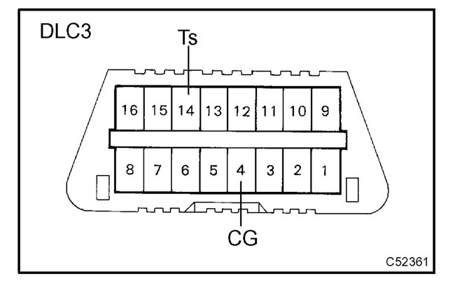
3. Using SST, repeat a cycle of short and open between terminals Ts and CG of DLC3 4 times or more within 8 sec. Check that the VSC indicator light is lit indicating the recorded zero point is erased.
SST 09843-18040

4. Turn the ignition switch OFF.

b. Obtain zero point of the yaw rate sensor.
1. Make the terminals Ts and CG of DLC3 disconnected.
2. Turn the ignition switch ON.

HINT: The vehicle should be in a stationary condition with the shift lever in P range.

3. Check that the VSC warning light goes off about 15 sec. after the ignition switch is turned ON.

HINT: Even if the ignition is not turned OFF in step (a) -(4) and remains ON, the yaw rate sensor zero point calibration can be completed. In this case, the VSC warning light is lit for about 15 sec. and then starts blinking. (Normal code)

4. After ensuring that the VSC warning light remains OFF for 2 sec., turn the ignition switch OFF.

HINT: If the ignition switch is not turned OFF in step (a) - (4), make sure that the VSC warning light blinks for 2 sec. Then turn the ignition switch OFF.

c. Perform deceleration sensor zero point calibration.

NOTE: After step (b) (the yaw rate sensor zero point calibration), the VSC warning light goes off. At this time, if the vehicle is driven without performing step (c) (deceleration sensor zero point calibration), deceleration sensor zero point calibration malfunction will be detected and the VSC warning light will light up. Therefore, perform step (c) right after step (b).

imageOpen In New TabZoom/Print

1. Using SST, connect the terminal Ts and CG of DLC3.
SST 09843-18040
2. Turn the ignition switch ON.

HINT: Place the vehicle in a stationary condition with the shift lever in P range.

imageOpen In New TabZoom/Print

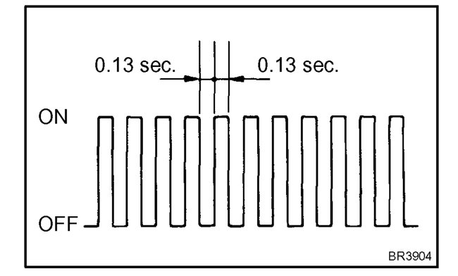
3. After turning the ignition switch ON, check that the VSC warning light is lit for about 4 sec. and then starts quick blinking at 0.13 sec. intervals.
4. After ensuring the blinking of the VSC warning light for 2 sec., turn the ignition switch OFF.
5. Remove the SST and make the terminals Ts and CG of DLC3 disconnected.
SST 09843-18040
Was this
answer
helpful?
Yes
No
+1
Thursday, November 5th, 2020 AT 6:33 AM
Tiny
CGOETZ1984
  • MEMBER
  • 16 POSTS
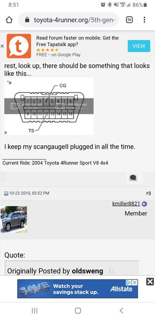
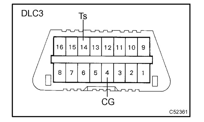
I just want to make sure I'm putting the wires in the right terminal because I keep getting different information one says 4 + 12. Your images are showing me 14 + 4.
Was this
answer
helpful?
Yes
No
Thursday, November 5th, 2020 AT 6:52 AM
Tiny
ASEMASTER6371
  • MECHANIC
  • 52,797 POSTS
That is correct. 4 and 14 are the ones.

Roy
Was this
answer
helpful?
Yes
No
Thursday, November 5th, 2020 AT 7:19 AM
Tiny
CGOETZ1984
  • MEMBER
  • 16 POSTS
So I performed the zero point calibration as you described. The lights did everything they were supposed to do I turn the engine off turned it back on but as soon as I put it in drive it came right back on. Am I doing something wrong?
Was this
answer
helpful?
Yes
No
Friday, November 6th, 2020 AT 5:56 AM
Tiny
ASEMASTER6371
  • MECHANIC
  • 52,797 POSTS
Okay, let us back up a little.

Why are you performing this?

Do you have a code stored in the system? If you do, what diagnostics and repairs have you done?

Roy
Was this
answer
helpful?
Yes
No
Friday, November 6th, 2020 AT 6:11 AM
Tiny
CGOETZ1984
  • MEMBER
  • 16 POSTS
No code, they just stayed on after I change the O2 sensors Bank 1 and bank 2.
Was this
answer
helpful?
Yes
No
Friday, November 6th, 2020 AT 6:40 AM
Tiny
ASEMASTER6371
  • MECHANIC
  • 52,797 POSTS
Okay, what are they? What lights?

Roy
Was this
answer
helpful?
Yes
No
Friday, November 6th, 2020 AT 7:00 AM
Tiny
CGOETZ1984
  • MEMBER
  • 16 POSTS
VSC trac and VSC trac off.
Was this
answer
helpful?
Yes
No
Friday, November 6th, 2020 AT 7:09 AM
Tiny
ASEMASTER6371
  • MECHANIC
  • 52,797 POSTS
Okay, thanks. There is a fault code stored for the system.

Standard code readers will not read those codes. You need an advanced scan tool to pull the code.

Once you get the code, post it for me so I can track it down for you.

Roy

System Outline

1. Normal Operation

The VSC system helps prevent the vehicle from slipping sideways as a result of strong front wheel skid or strong rear wheel skid during cornering.

The followings are two examples that can be considered as circumstances in which the tires exceed their lateral grip limit. The VSC system is designed to help control the vehicle behavior by controlling the engine's output and the brakes at each wheel when the vehicle is under one of the conditions indicated below.
When the front wheels lose grip in relation to the rear wheels (Strong front wheel skid tendency).
When the rear wheels lose grip in relation to the front wheels (Strong rear wheel skid tendency).

2. Downhill Assist Control Operation
The downhill assist control operation controls braking action of each wheel to help prevent out of balance vehicle posture when descending a steep hill or traveling at a speed exceeding the threshold of wheel gripping capability. When the downhill assist control is in operation, the brake system controls vehicle speed within the range of 5 to 7 km/h.

For the downhill assist control to be operative all of the following conditions have to be met:
Downhill assist control switch = ON
Transfer L4 selected
Vehicle speed is 5 km/h or more, but less than 25 km/h.
Accelerator pedal OFF
Brake pedal OFF

3. Hill Start Support Control Operation
When starting on a steep hill for ascending, the hill start support control automatically puts the brake on momentarily from the moment when the driver releases his foot from the brake pedal until he steps on the accelerator pedal to help the driver start the vehicle safely and smoothly. Please bear in mind, however, that it activates the brake system for only 3 seconds.

For the hill start support control to be operative all of the following conditions have to be met:
Shift position = D, 2, or L
Vehicle not moving forward with some wheel(s) slipping
Vehicle speed > 0 km/h.
Was this
answer
helpful?
Yes
No
Friday, November 6th, 2020 AT 7:23 AM

Please login or register to post a reply.

Related General Content

Sponsored links