Hi and thanks for using 2CarPros.com.
First, here is a link that discusses hard starts. Take a look through it.
https://www.2carpros.com/articles/engine-cranks-excessively-before-starting
Next, I suggest checking fuel pressure and the regulator. Here is a link that describes how it is done:
https://www.2carpros.com/articles/how-to-check-fuel-system-pressure-and-regulator
If you determine the regulator is bad, here are the directions for replacement. All attached pictures correlate with the following sets of directions.
______________________________
FUEL PRESSURE REGULATOR: REMOVAL
1. DISCHARGE FUEL SYSTEM PRESSURE See: Fuel Injector > Removal and Replacement > Removal
2. REMOVE V-BANK COVER See: Intake Manifold > Removal and Replacement > Removal
3. REMOVE AIR CLEANER HOSE ASSEMBLY See: Intake Manifold > Removal and Replacement > Removal
4. REMOVE NO. 2 FUEL TUBE SUB-ASSEMBLY See: Fuel Injector > Removal and Replacement > Removal
5. REMOVE FUEL PRESSURE REGULATOR ASSEMBLY
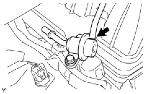
(a)Disconnect the vacuum sensing hose from the fuel pressure regulator.
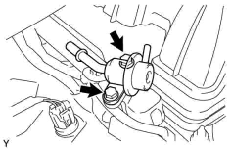
(b)Remove the 2 bolts, and pull out the fuel pressure regulator.
(c)Remove the O-ring from the pressure regulator.
__________________________________
If you determine the pump is bad, here are the directions for replacement.
REMOVAL
3UR-FE FUEL: FUEL PUMP: REMOVAL
1. REMOVE FUEL TANK ASSEMBLY
(a)Remove the fuel tank assembly See: Fuel Tank > Removal and Replacement > Removal.
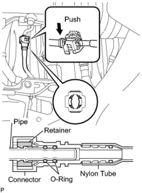
2. REMOVE FUEL SUCTION WITH PUMP AND GAUGE TUBE ASSEMBLY
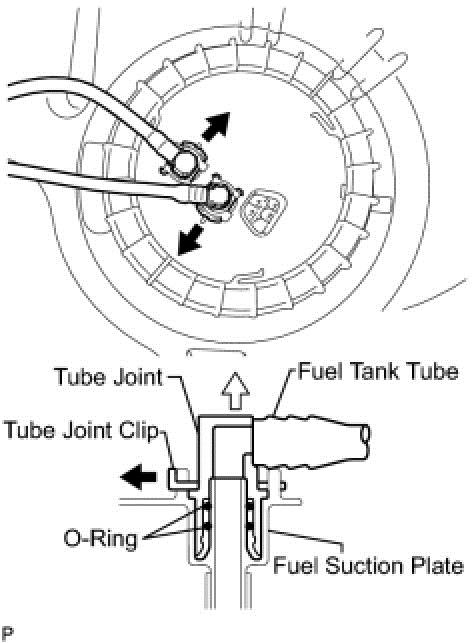
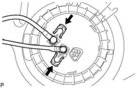
(a)Remove the 2 tube joint clips and pull out the 2 fuel tank tubes.
NOTICE:
* Remove any dirt and foreign matter on the fuel tube joint before performing this work.
* Do not allow any scratches or foreign matter on the parts when disconnecting them, as the fuel tube joint contains the O-rings that seal the plug.
* Perform this work by hand. Do not use any tools.
* Do not forcibly bend, twist or turn the nylon tube.
* Protect the disconnected part by covering it with a plastic bag and tape after disconnecting the fuel tubes.
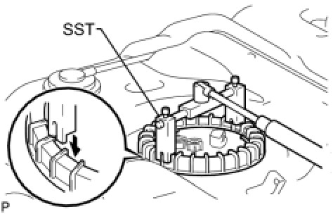
(b)Using SST, loosen the retainer.
SST : 09808-14020
HINT
Fit the tips of SST onto the ribs of the retainer.
NOTICE:
* When the retainer is loosened, be careful as the fuel suction with pump and gauge tube assembly will spring upward from the force of the spring.
* Clean the fuel suction with pump and gauge tube assembly before this operation.
(c)Remove the retainer.
(d)Remove the fuel suction with pump and gauge tube assembly from the fuel tank.
NOTICE:
Be careful not to bend the arm of the fuel sender gauge.
(e)Remove the gasket from the fuel tank.
_________________________________
INSTALLATION
3UR-FE FUEL: FUEL PUMP: INSTALLATION
1. INSTALL FUEL SUCTION WITH PUMP AND GAUGE TUBE ASSEMBLY
(a)Apply a light coat of gasoline or grease to a new gasket, and install it to the fuel tank.
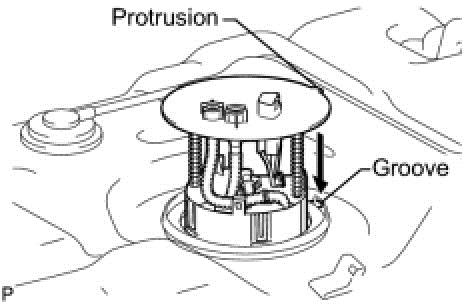
(b)Align the protrusion of the fuel suction with pump and gauge tube assembly with the groove of the fuel tank.
(c)Install the fuel suction with pump and gauge tube assembly into the fuel tank.
NOTICE:
Be careful not to bend the arm of the fuel suction with pump and gauge tube assembly.
(d)Put the retainer on the fuel tank. While holding the fuel suction with pump and gauge tube assembly, tighten the retainer one complete turn by hand.
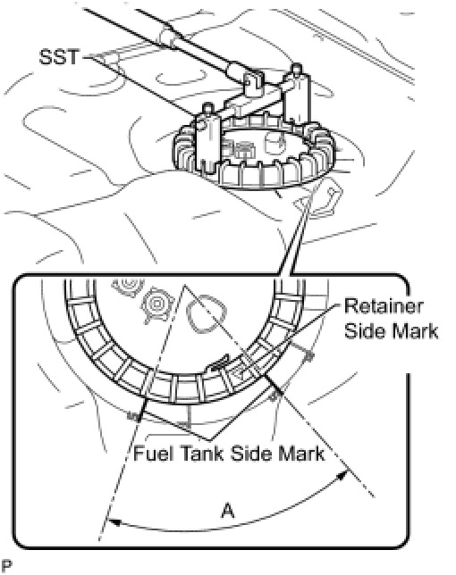
(e)Using SST, tighten the retainer until the mark on the retainer is within range A on the fuel tank, as shown in the illustration.
SST : 09808-14020
HINT
Fit the tips of SST onto the ribs of the retainer.
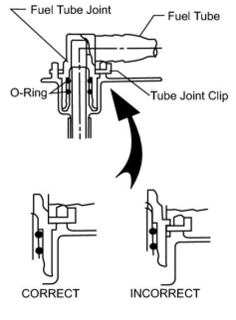
(f)Install the 2 fuel tank tubes with the 2 tube joint clips.
NOTICE:
* Check that there are no scratches or foreign objects on the connecting parts.
* Check that the fuel tube joints are inserted securely.
* Check that the tube joint clips are on the collars of the fuel tube joints.
* After installing the tube joint clips, check that the fuel tube joints have not been pulled off.
2. INSTALL FUEL TANK ASSEMBLY
(a)Install the fuel tank assembly See: Fuel Tank > Removal and Replacement > Installation.
___________________________________
Here are the directions for removing the fuel tank:
__________________________________
REMOVAL
3UR-FE FUEL: FUEL TANK: REMOVAL
1. DISCHARGE FUEL SYSTEM PRESSURE
See: Fuel Delivery and Air Induction > Technician Safety Information
2. REMOVE FUEL TANK CAP
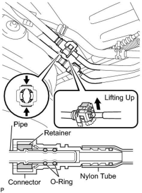
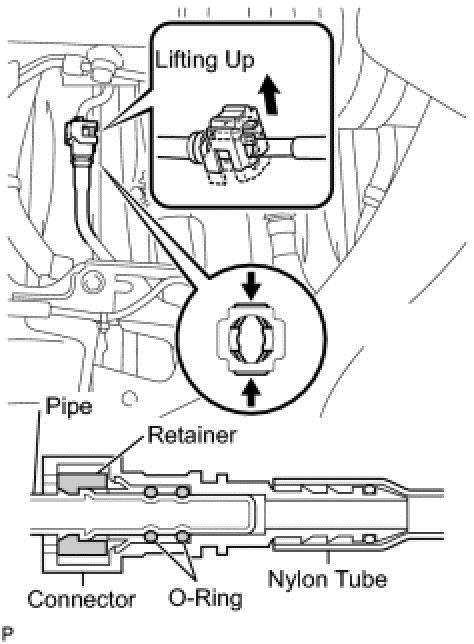
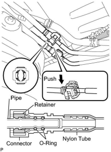
3. DISCONNECT FUEL TANK MAIN TUBE SUB-ASSEMBLY
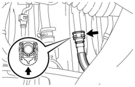
(a)Detach the lock claw by lifting up the cover, as shown in the illustration.
(b)Pinch and pull the main tube connector to disconnect the fuel tank main tube sub-assembly connector from the pipe.
NOTICE:
* Check for foreign matter in the pipe and around the connector. Clean if necessary. Foreign matter may damage the O-ring or cause leaks in the seal between the pipe and connector.
* Do not use any tools to separate the pipe and connector.
* Do not forcefully bend or twist the nylon tube.
* Check for foreign matter on the pipe seal surface. Clean if necessary.
* Put the pipe and connector ends in plastic bags to prevent damage and foreign matter contamination.
* If the pipe and connector are stuck together, pinch the connector between your fingers and turn it carefully to disconnect it.
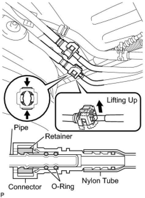
4. DISCONNECT FUEL TANK RETURN TUBE
(a)Detach the lock claw by lifting up the cover, as shown in the illustration.
(b)Pinch and pull the return tube connector to disconnect the fuel tank return tube connector from the pipe.
NOTICE:
* Check for foreign matter in the pipe and around the connector. Clean if necessary. Foreign matter may damage the O-ring or cause leaks in the seal between the pipe and connector.
* Do not use any tools to separate the pipe and connector.
* Do not forcefully bend or twist the nylon tube.
* Check for foreign matter on the pipe seal surface. Clean if necessary.
* Put the pipe and connector ends in plastic bags to prevent damage and foreign matter contamination.
* If the pipe and connector are stuck together, pinch the connector between your fingers and turn it carefully to disconnect it.
5. REMOVE FUEL TANK ASSEMBLY
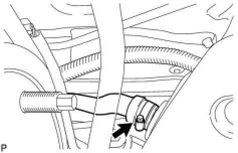
(a)Disconnect the fuel tank to filler pipe hose from the fuel tank assembly.
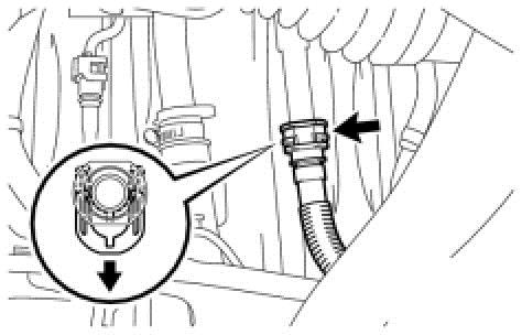
(b)Pull up the retainer and disconnect the vent line hose.
(c)Detach the lock claw by lifting up the cover, as shown in the illustration.
(d)Disconnect the fuel tank breather tube from the fuel tank inlet pipe sub-assembly.
(e)Set a mission jack underneath the fuel tank assembly.
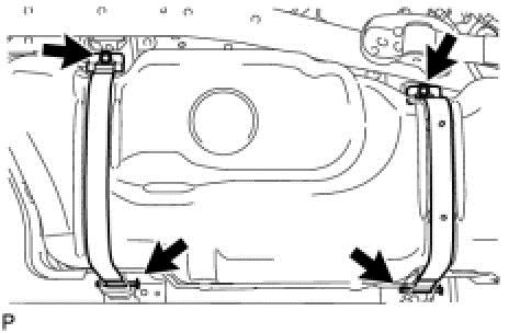
(f)Remove the 2 bolts, 2 clips, 2 pins and 2 fuel tank bands.
(g)Slowly lower the mission jack slightly.
NOTICE:
Be careful not to cut the wirings.
(h)Disconnect the wire harness clamp from the fuel tank assembly.
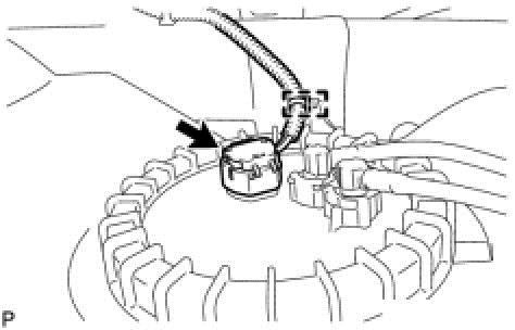
(i)Disconnect the fuel pump connector and lower the mission jack.
NOTICE:
* Before this procedure, check the connector for dirt, mud or other contamination.
* Do not use any tools in this procedure.
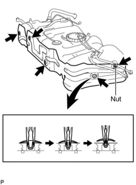
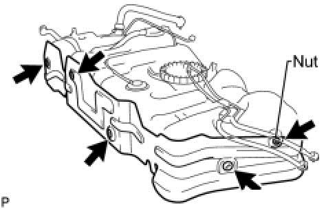
6. REMOVE NO. 1 FUEL TANK HEAT INSULATOR
(a)Remove the nut from the heat insulator.
(b)Using needle-nose pliers, remove the 4 clips shown in the illustration and then remove the No. 1 fuel tank heat insulator.
7. REMOVE FUEL SUCTION WITH PUMP AND GAUGE TUBE ASSEMBLY
_________________________________
FUEL TANK: INSTALLATION
1. INSTALL FUEL SUCTION WITH PUMP AND GAUGE TUBE ASSEMBLY See: Fuel Pump > Removal and Replacement > Installation
2. INSTALL NO. 1 FUEL TANK HEAT INSULATOR
(a)Install the No. 1 fuel tank heat insulator with the 4 clips and nut.
Torque : 6.0 Nm (61 kgf-cm, 53 in-lbf)
3. INSTALL FUEL TANK ASSEMBLY
(a)Set the fuel tank on a transmission jack and raise the fuel tank assembly.
(b)Connect the wire harness clamp and fuel pump connector to the fuel tank assembly.
NOTICE:
Be careful not to cut the wirings.
(c)Raise the transmission jack.
(d)Install the 2 fuel tank bands with the 2 pins and 2 clips.
(e)Connect the 2 fuel tank bands with the 2 bolts.
Torque : 40 Nm (408 kgf-cm, 30 ft-lbf)
(f)Connect the fuel tank breather tube to the fuel tank inlet pipe sub-assembly.
HINT
Push the parts together firmly until a "click" sound is heard.
NOTICE:
* Before installing the tube connectors to the pipes, check if there is any damage or foreign matter in the connectors.
* After the connection, check if the connectors and pipes are securely connected by trying to pull them apart.
(g)Connect the vent line hose and install the retainer.
NOTICE:
* Before installing the hose, make sure that it is not damaged. Make sure that there is no foreign matter present on the connecting surfaces.
* After connecting, check if the hose and the connector are securely connected by pulling on them.
(h)Connect the fuel tank to filler pipe hose to the fuel tank assembly.
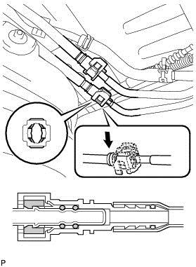
4. CONNECT FUEL TANK RETURN TUBE
(a)Connect the fuel tank return tube.
HINT
Push the parts together firmly until a "click" sound is heard.
NOTICE:
* Before installing the tube connectors to the pipes, check if there is any damage or foreign matter in the connectors.
* After the connection, check if the connectors and pipes are securely connected by trying to pull them apart.
(b)Attach the lock claws to the connector by pushing down on the cover, as shown in the illustration.
5. CONNECT FUEL TANK MAIN TUBE SUB-ASSEMBLY
(a)Connect the fuel tank main tube.
HINT
Push the parts together firmly until a "click" sound is heard.
NOTICE:
* Before installing the tube connectors to the pipes, check if there is any damage or foreign matter in the connectors.
* After the connection, check if the connectors and pipes are securely connected by trying to pull them apart.
(b)Attach the lock claws to the connector by pushing down on the cover, as shown in the illustration.
6. INSTALL FUEL TANK CAP
7. INSPECT FOR FUEL LEAK
____________________________________
I hope this helps. Let me know if you have other questions.
Take care,
Joe
Images (Click to enlarge)
Oct 19, 2018 at 9:35 PM