What is the light blinking on the left? I can't see it from the video, is it a security light? I have seen this problem before and it ended up being the smart junction box on the left kick panel, sometimes they get water in the box or the wiring connectors which will cause the issue as well, but to be sure we can run a CAN scan which is easy to do. Please watch this video and read the guide to show you how. I have also included how to change the SJB out in case it is the problem after the scan so you know what you might be in for.
https://www.2carpros.com/articles/can-scan-controller-area-network-easy
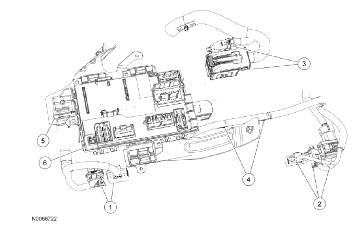
Check the diagrams below
Removal
NOTICE: If the Smart Junction Box (SJB) is dropped, damage to the internal components may occur. A new SJB must be installed.
NOTICE: Electronic modules are sensitive to static electrical charges. If exposed to these charges, damage may result.
NOTE: Prior to the replacement of the module, it is necessary to upload the module configuration information to the scan tool. This information must be downloaded into the new module after installation. For additional information, refer to Module Configuration See: Information Bus > Testing and Inspection. In the event that As-Built data is required (the SJB does not communicate), all Remote Keyless Entry (RKE) devices must be programmed to the new SJB. A minimum of 2 devices are necessary to complete the configuration and turn off the flashing interior lights.
NOTE: The Tire Pressure Monitoring System (TPMS) functionality is integral to the SJB.
NOTE: The steps included in the SJB removal and installation procedure are critical to restoring the vehicle security and the TPMS to normal operation. A new SJB is delivered in a manufacturing mode with 8 pre-set DTCs related to the TPMS. To clear the DTCs, successful configuration of the SJB must occur, followed by successful TPMS sensor training, and a successful self-test, including clearing of the DTCs. The DTCs are as follows:
- B106D (Tire Pressure Monitor System [ TPMS] Initiators Not Configured)
- B2477 (Module Configuration Failure)
- B2868 (Left Front Tire Pressure Sensor Fault)
- B2869 (Right Front Tire Pressure Sensor Fault)
- B2870 (Right Rear Tire Pressure Sensor Fault)
- B2871 (Left Rear Tire Pressure Sensor Fault)
- B2A21 (One or More Configuration Files Missing or Corrupt)
- C2780 ( ECU in Manufacturer Sub-State)
1. NOTE: This step is necessary only if the SJB is being replaced.
Upload the module configuration information from the SJB. For additional information, refer to Module Configuration See: Information Bus > Testing and Inspection.
2. Remove the steering column opening trim panel. For additional information, refer to Instrument Panel and Console See: Dashboard / Instrument Panel > Removal and Replacement > Instrument Panel - Exploded View.
3. Disconnect the SJB electrical connectors.
4. Remove the 2 harness pushpins from the SJB.
5. Using a suitable tool, lift the SJB release tab (away from the SJB bracket), slide the SJB (wiggling it to the left) and remove.
6. Disconnect the SJB B+ (battery lead, part of the 14290 harness) connector.
7. If necessary, remove the 3 nuts and the SJB bracket.
Installation
1. NOTE: Align the SJB bracket to the upper 2 mounting studs, then rotate the bracket onto the lower mounting stud.
If necessary, install the 3 nuts and the SJB bracket.
2. Install the SJB.
- Connect the SJB B+ (battery lead, part of the 14290 harness) connector.
- Locate the SJB into the 3 tabs and slide the SJB (to the right) to engage the SJB release tab into the SJB bracket.
- Connect the electrical connectors.
- Install the 2 harness pushpins into the SJB.
3. NOTE: If the SJB was not replaced, this is the last step that is necessary.
Install the steering column opening trim panel.
4. NOTE: The RKE transmitter portion of the Integrated Keyhead Transmitter (IKT) key is automatically transferred during Programmable Module Installation (PMI). Passive Anti-Theft System (PATS) programming is not necessary. If As-Built data is required during PMI, all (IKT or fob) remote transmitters must be programmed to the new SJB. Cycling the ignition to run for 6 seconds with each IKT programs the RKE function of the IKT key. For additional information, refer to Handles, Locks, Latches and Entry Systems for the remote transmitter programming instructions.
NOTE: DTC B2276 may be set, indicating there are less than 2 transmitters programmed to the SJB. For additional information, refer to Handles, Locks, Latches and Entry Systems .
Download the SJB configuration information from the scan tool. For additional information, refer to Module Configuration See: Information Bus > Testing and Inspection.
5. Train the tire pressure sensors. For additional information, refer to Wheels and Tires See: Tire Monitoring System > Programming and Relearning.
6. NOTE: DTC C2780 does not clear if any of the pre-set DTCs are still present in the SJB. When successful, this step clears the DTC C2780.
Carry out the SJB self-test (must include an on-demand self-test) and then repeat the self-test to confirm all DTCs have been cleared.
7. Rotate the instrument panel dimmer switch from the full dim position to the dome ON position to calibrate the switch. This makes sure that all displays are visible under all lighting conditions.
Check out the diagrams (below). Please let us know what you find. We are interested to see what it is.
May 17, 2022 at 9:37 AM