Wiring harness issues for replacement door?

Tiny
COLLIN WILLIAMS
  • MEMBER
  • 2011 TOYOTA CAMRY
  • 2WD
  • AUTOMATIC
  • 80,000 MILES
2CarPros,

To start off a friend turned me onto your site. He said you guys were really good at helping with all kinds of issues.

In any event I'm not sure if you can help me with this but I'm going to ask.

My next-door neighbor, she's a senior and hit a concrete pylon with her left rear door of her car listed above and put a huge scrape and dent in it. Body shop was going to charge her $3,000.00 to fix it, but I was able to find the same door, same paint color on eBay for $500.00. It was off of a 2007 Camry, but the 2007-2011 Camry doors are all the same, so the fit was good. What wasn't the same was the electrical harness to the electric window and door lock. Anyway, since the body of the door is the same, I could just simply pull the window, motor, and switch from the damaged door and put it on the replacement door. The only issue is that I can't take the motor or switch out because the window is in the up position and since the harness is different, I can't get the window down. Actually, both windows on both doors are in the up position and I need to get them down in order to remove the window, motor, and lock switch. You guys have any ideas as to how I can get these windows down since the original door is already off and the replacement door already on? Thank you for any hints
Sunday, April 23rd, 2023 AT 6:09 PM

12 Replies

Tiny
CARADIODOC
  • MECHANIC
  • 33,737 POSTS
To get you started, these first seven diagrams are for the entire power window system. The next four show the connector views. I found the two you might need in the second and the fourth drawings. Next two pages are the description of how the system works, but they left out one important detail.

The last diagram is a copy of the seventh, for the left rear window. I added notes to the wires you'll need, but if you can reach the two wires to the motor, that will be easier, but only if that assembly is not plugged into the car.

The two ground wires are obvious. Hook both of them to the negative post of a battery. The red wire is also easy to see that it must go to the battery's positive post. The wire in question is the pink wire. That one comes from the Body Computer after it gets a command from the driver's master switch, but they don't say what kind of signal that is. It could be as simple as 12 volts, in which case you'd also connect that wire to the battery's positive post. It might also be some type of digital signal. Those commonly switch between 0.0 and 5.0 volts. Putting 12 volts on it could damage the computer module on that window motor. If it comes to that, I would suggest first going to the right rear door, and measuring the voltage there. Digital voltmeters can't measure a digital signal, but if the display bounces around, I would not want to try putting 12 volts on that pink wire. The better alternative would be to place the old door close enough to the car so you can connect those plugs with small jumper wires if you have to.

If you can reach the two wires on the motor, that would be the easier way to run the motor, but that must be done with the connector not plugged into the car. The reason is if you follow the orange and green wires down from the module, you'll see they both go through a switch, then to ground. In effect, that motor is shorted out. You'll melt your jumper wires.

I have to stop here and point out the engineers decided this circuit was too easy to diagnose so they had to add some complexity to it. In all older power window systems, both motor terminals are grounded when that circuit is at rest. You can read the continuity to ground from each wire, but to be accurate, you have to unplug at least one of them, otherwise a circuit with a break in it would falsely read okay by reading through the motor, then to ground through the other wire.

When you activate a switch, one part of it stays at rest and stays connected to ground as before. It's the other switch that moves away from ground, then makes a connection to the 12-volt terminal. The motor runs one way. When you press the window switch the other way, the rolls reverse. Now it's that second switch that stays at rest, (grounded), while the first one moves away from the ground wire and gets connected to the 12-volt wire. The polarity is reversed and the motor runs the other way.

The important point here is if you were to connect 12 volts and ground directly to the motor while it is in the vehicle and connected to the original wires, both of them are connected to ground, so you'd have a direct short across the test battery. You have to unplug the wire from at least one motor terminal first.

In this Toyota circuit, that polarity switching is done inside the module. I'm pretty sure you will have that same short if you put 12 volts and ground directly to the motor. If you can get to just one of the motor's wires to unplug it or unsolder it, you can use the battery directly with two jumper wires. If the motor's terminals are buried or not accessible, you'll have to let the module do its thing. This is where the red and two black wires must be connected to the battery, but I don't know what to tell you for the pink wire. Try it first with the pink wire connected to nothing. If it doesn't work, we'll need to figure out what that voltage or signal looks like on the right rear door.

If you're willing to run some longer wires, connect them to the car's connector. That will ensure whatever the Body Computer is sending down the pink wire will be correct and nothing will be damaged.

If you need me to enlarge the connector views, let me know, otherwise tell me how far this gets you.
Was this
answer
helpful?
Yes
No
Sunday, April 23rd, 2023 AT 7:39 PM
Tiny
COLLIN WILLIAMS
  • MEMBER
  • 10 POSTS
Thanks so much for the very detailed information. Unfortunately, my electrical schematic reading skills aren't the best. The 2011 harness is the first picture, the seven-wire connection, and the 2007 window regulator is one of the last two picture (I couldn't remember which connection was which for the 2007 so I apologize) Can you make any sense out of the harnesses and the specific wires? I was not able to find any type of automotive electronic wiring descriptions based on the coloring for the wire. Thanks again in advance.
Was this
answer
helpful?
Yes
No
Monday, April 24th, 2023 AT 5:33 PM
Tiny
CARADIODOC
  • MECHANIC
  • 33,737 POSTS
I'm sorry that I totally overlooked the 2007 model. These first five diagrams are for that year. The last one is a repeat of the fourth diagram with an arrow pointing to the left rear window. There's no module tacked onto the passenger window motors, so getting this motor to run will be easier.

When I described the older systems yesterday, this is a version of that. When all switches are released, both left rear motor wires will have continuity to ground, but that's by reading through the wires and the driver's switch, then to ground. All you have to do is unplug that connector, then connect the battery to the purple and orange wires at the motor, or at the switch. You could also use the yellow and light blue wires. That would put the 12 volts and the polarity to the motor just as the driver's switch does.

Remember, this connector has to be unplugged when applying the 12 volts, otherwise there will be a direct short back through the driver's switch.
Was this
answer
helpful?
Yes
No
+1
Monday, April 24th, 2023 AT 6:13 PM
Tiny
COLLIN WILLIAMS
  • MEMBER
  • 10 POSTS
Good evening. Back from vacation and back to the grind. I used some basic common sense, and I think you actually mentioned this earlier, but I took the old door, although detached, and hooked it back up to the car connection and simply used the car window button to roll down the window lol. Amazing what some basic common logic will do. I'm now taxed with getting the 2007 Camry window down. I'll re read your previous replies and see if I can figure out what terminals to supply power to to get that window down. Fortunately the 2007 Camry only has 5 wires where as the 2011 Camry had about 12 wires, both large and small. I really appreciate your help with this. Thank you
Was this
answer
helpful?
Yes
No
Tuesday, May 9th, 2023 AT 6:03 PM
Tiny
CARADIODOC
  • MECHANIC
  • 33,737 POSTS
So far, so good. Keep me posted.
Was this
answer
helpful?
Yes
No
+1
Tuesday, May 9th, 2023 AT 6:55 PM
Tiny
COLLIN WILLIAMS
  • MEMBER
  • 10 POSTS
Good evening. I've tried my best to follow the electrical schematics you provided but I'm just not good at reading automotive electrical schematics. I tried to look up the color codes for the electrical wiring for a 2007 Toyota Camry, but what I found doesn't match what I have lol. I'm hoping you might be able to elaborate a little more on the wiring.
This is what I have.
The main connection on this harness has five wires on it. A black wire, a blue wire, a yellow wire, a green wire, and a red wire. The window motor connection also has five wires on it. Two red wires, a purple wire, a green wire, and a yellow wire (as shown in the picture)
From the main connection one of the red wires, the yellow wire, and the green wire all have continuity to the window motor connection.
The window up and down switch connection has two wires to it, a purple wire and the other red wire red wire (re: the above two red wires). Those two wires have continuity from the window motor connection to the window up and down switch. The exterior door handle switch has a black and a blue wire running to it, so, as best I can tell, the black and blue wires off of the main connection are irrelevant since they are both specific to the exterior door handle switch.
Here are my thoughts on the wiring: The red wire on the main connection and the "first" red wire on the window motor connection must be the positive connection (from the battery). The green wire on the main connection and the green wire on the window motor connection must be the ground. The yellow wire from the main connection and the window motor connection is what I'm not sure of. Maybe the neutral wire?
Since the purple wire and the "second" red wire have continuity from the window motor switch to the window up and down switch my thoughts are that those two wires (purple wire and the "second" red wire) are responsible for the direction of the window.
After this I'm trying to figure out how to jump the contacts, I would think I would jump the two red wires on the window motor connection to supply power to the window motor connection (since one of the red wires has continuity from the main harness to the window motor)
After that I'm lost since there is only one connection with continuity from the window motor switch to the window up and down switch.
Any advice? Thanks so much!
FYI the picture included is a picture of the harness, with the main connection being on the right, with the window motor connection next to it (middle) with the window up and down switch being next to that (last connection on left).
Was this
answer
helpful?
Yes
No
Wednesday, May 10th, 2023 AT 7:07 PM
Tiny
CARADIODOC
  • MECHANIC
  • 33,737 POSTS
I thought the 2007 would be the easy one. I'll have to ignore you for a little while so I can piece these diagrams together. They're too hard for anyone to follow when they're in so many pieces. I'll be back as soon as I have a better answer. Look back at my reply where I posted the 2007 diagrams. I'm going to double-check the colors you listed so I'm sure I'm telling you the right thing.
Was this
answer
helpful?
Yes
No
+1
Wednesday, May 10th, 2023 AT 9:00 PM
Tiny
COLLIN WILLIAMS
  • MEMBER
  • 10 POSTS
Take your time. I appreciate any advice you can offer.
I'm going to try and rationalize my way through this and if I'm able to figure it out before I hear back, I'll let you know. Thanks again.
Was this
answer
helpful?
Yes
No
Thursday, May 11th, 2023 AT 5:41 AM
Tiny
CARADIODOC
  • MECHANIC
  • 33,737 POSTS
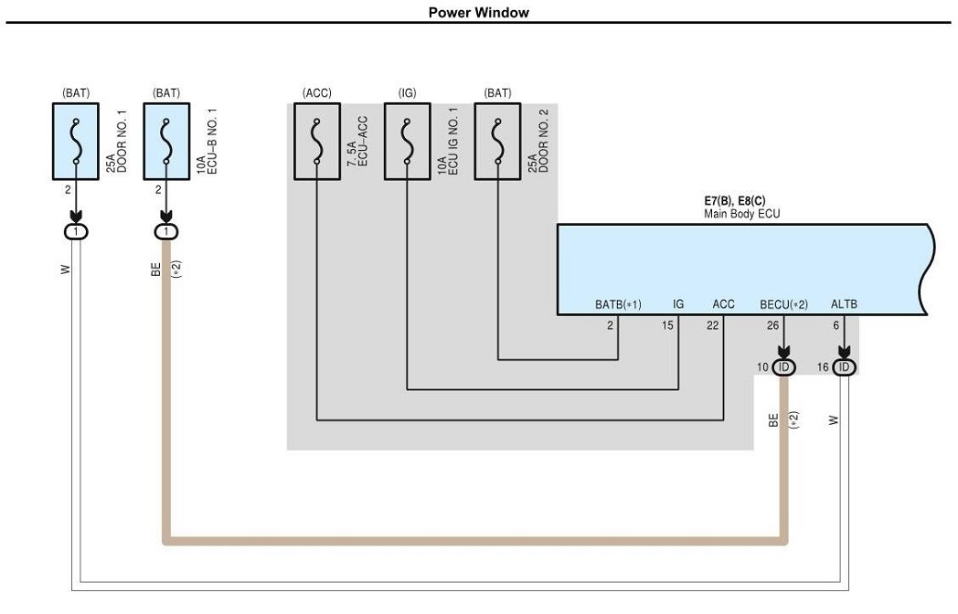
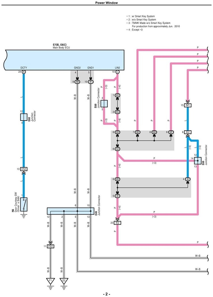
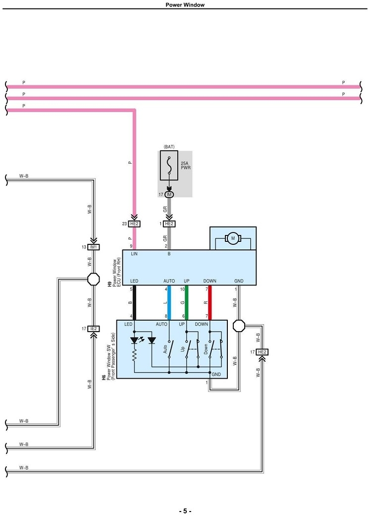
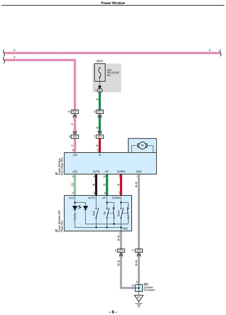
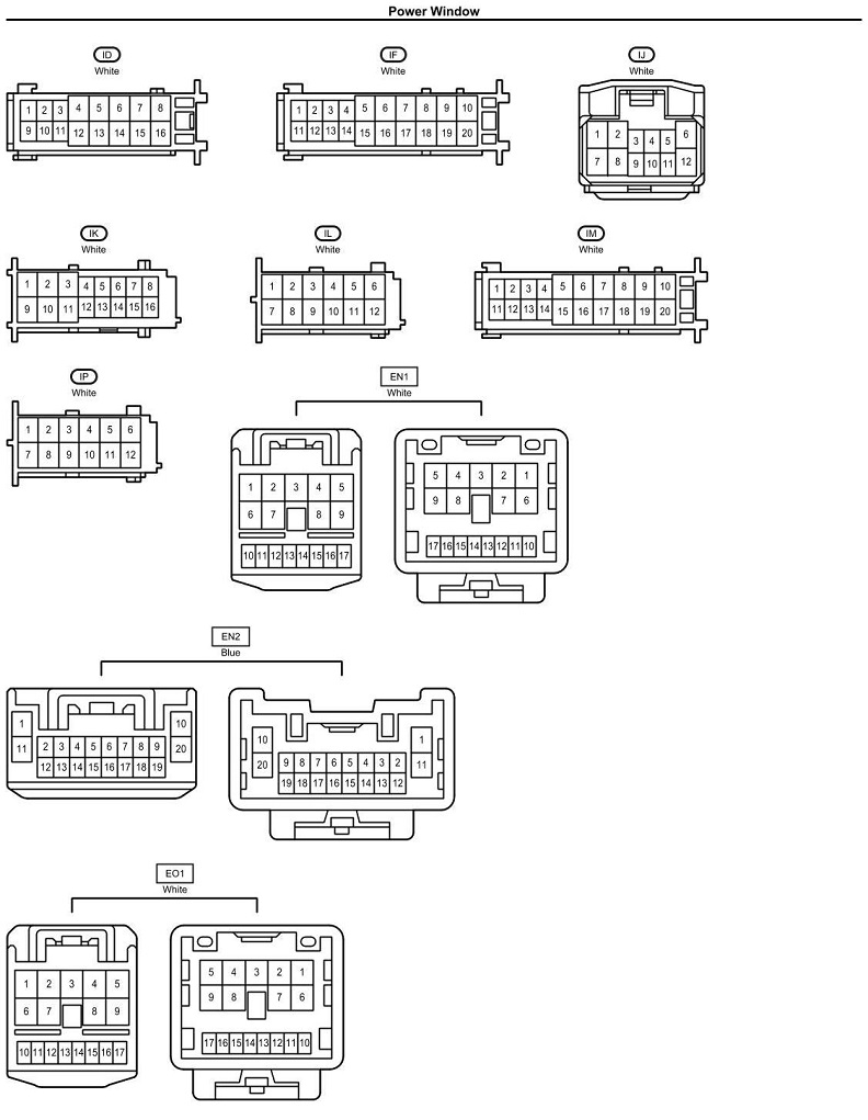
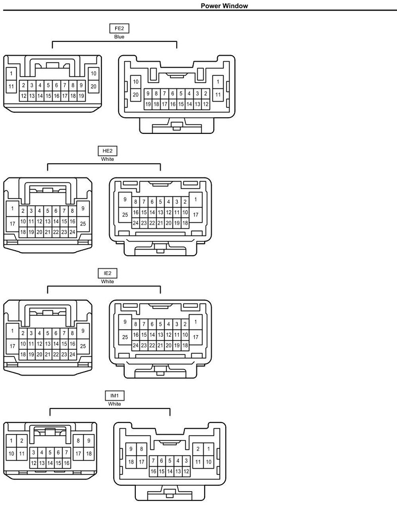
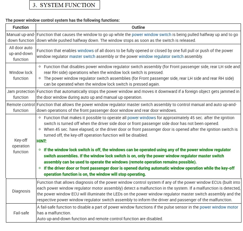
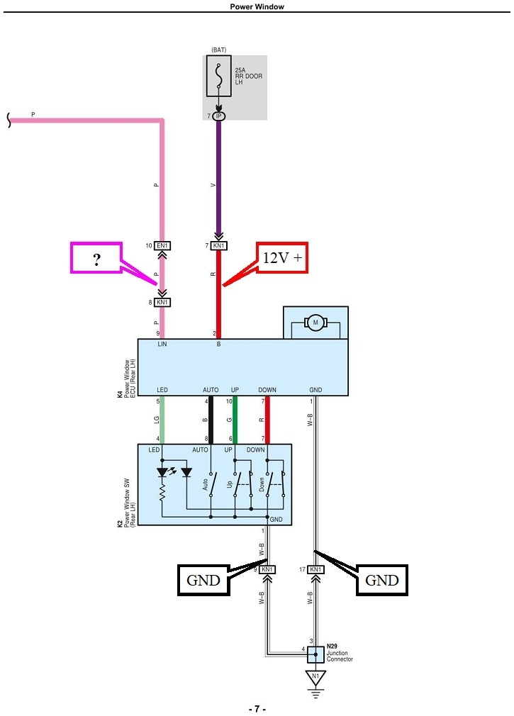
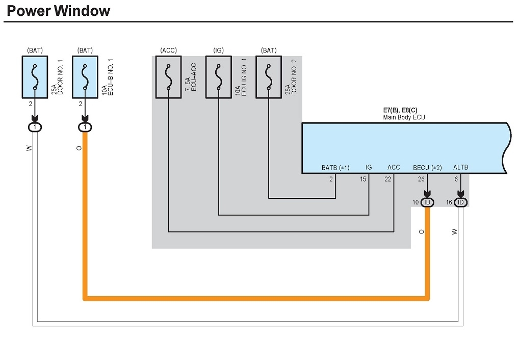
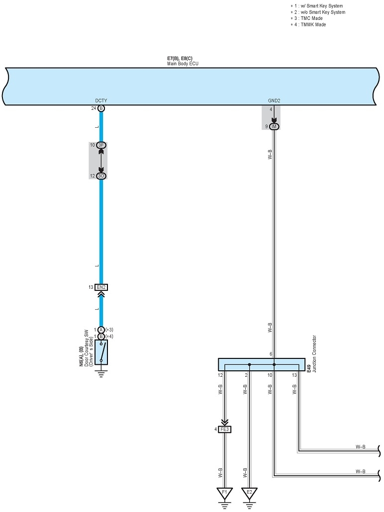
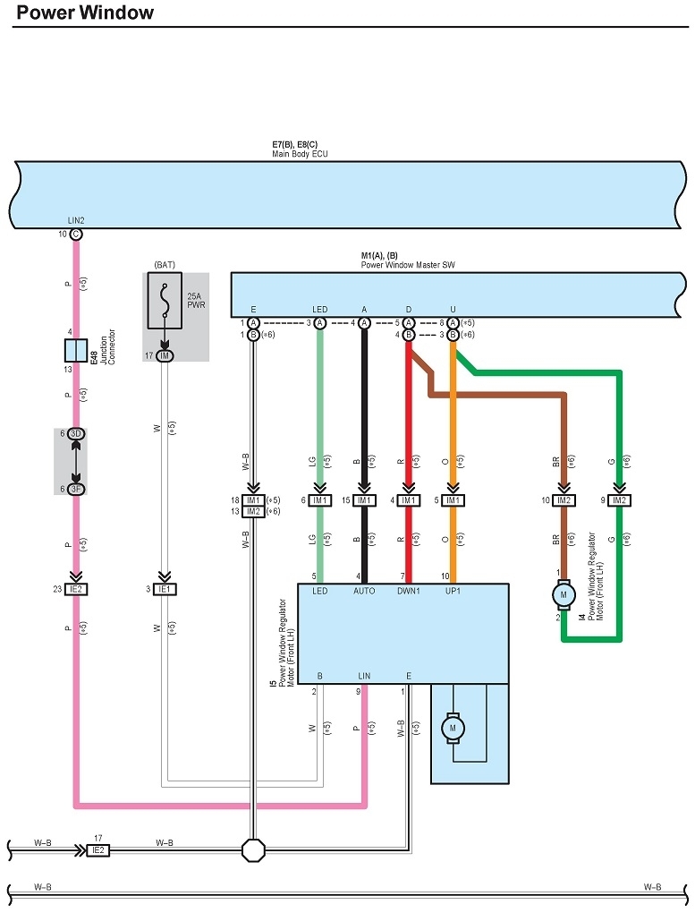
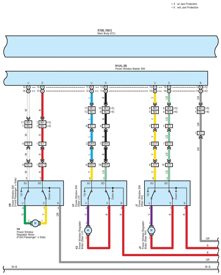
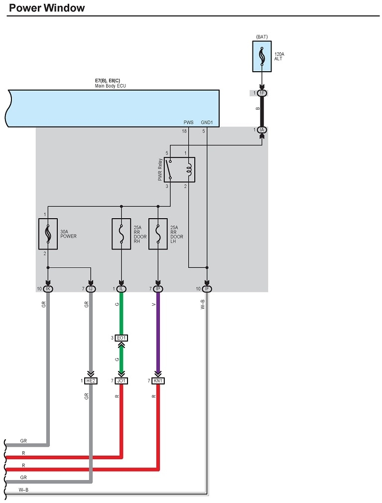
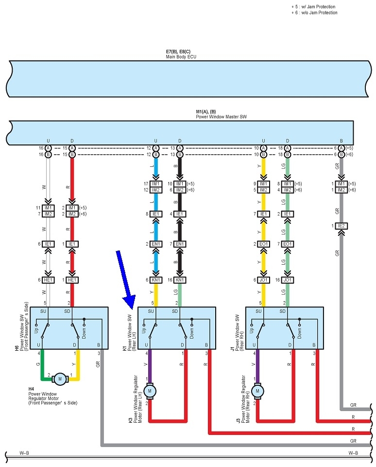
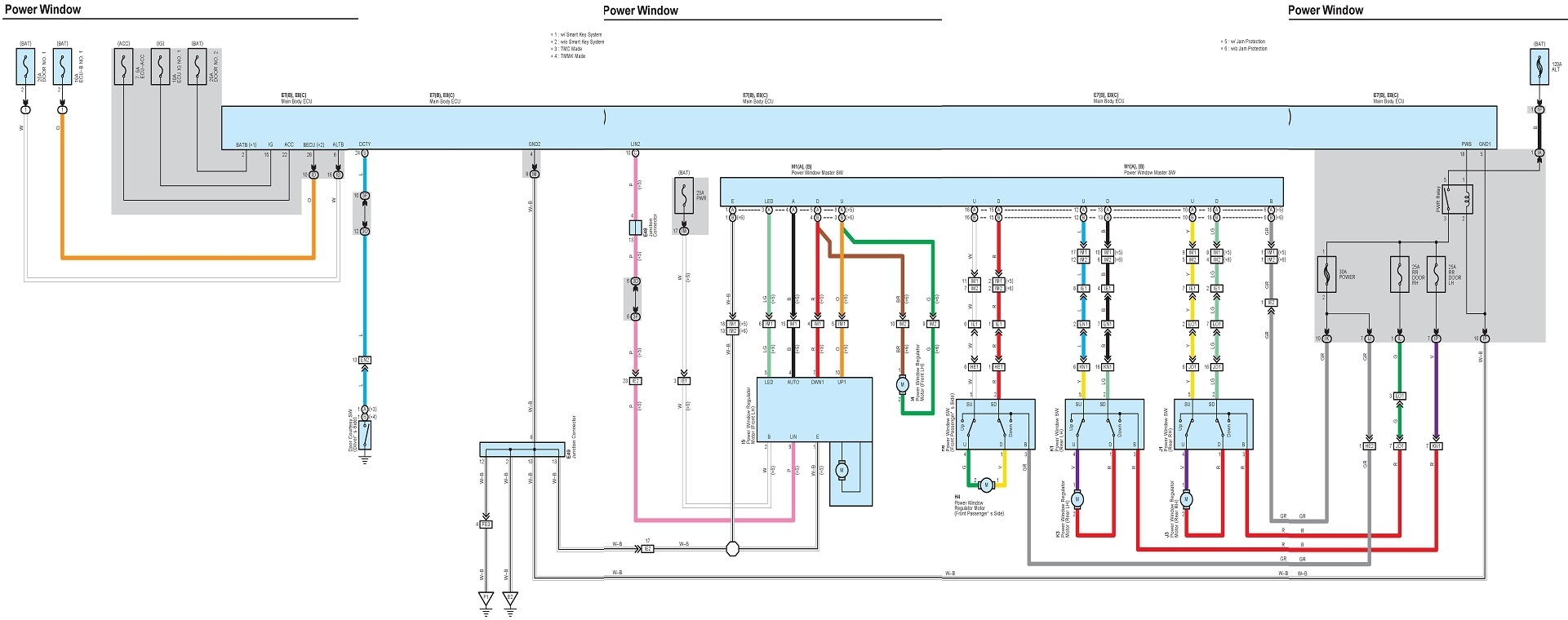
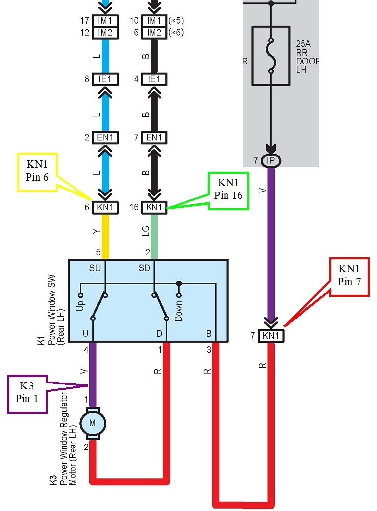
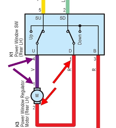
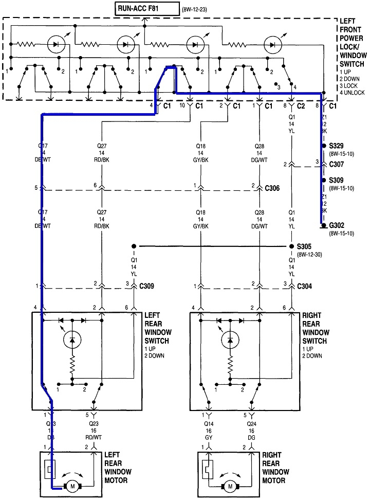
Okay, here's what I put together. The first diagram, (suitable for framing), is the entire window system. The second diagram is just the left rear circuit. Everything else is chopped off to reduce confusion.

You have this mostly correct.

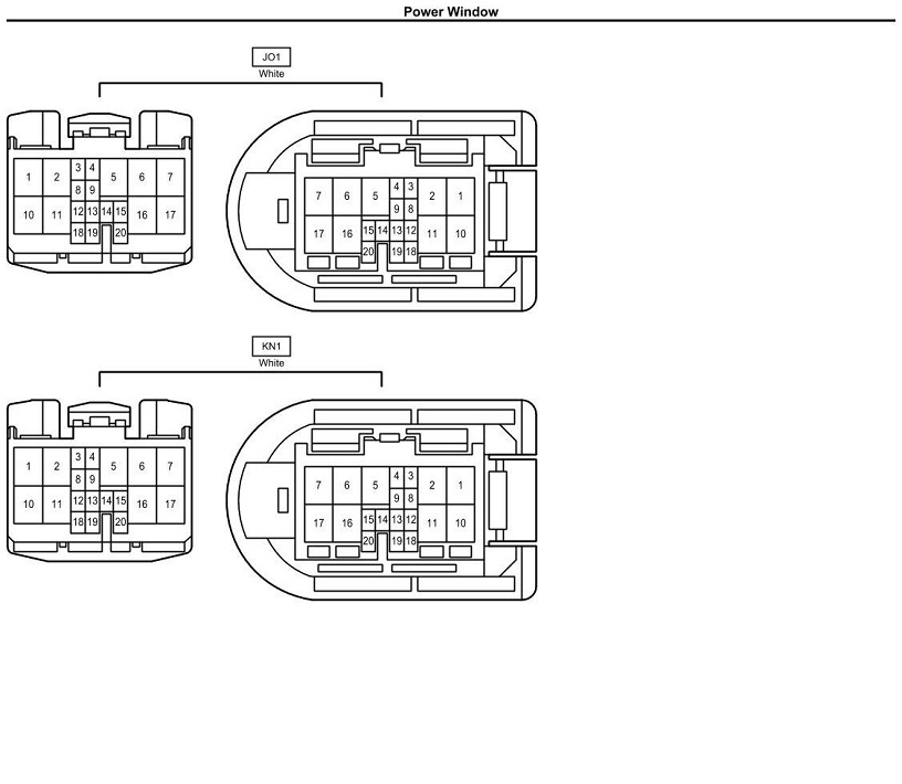
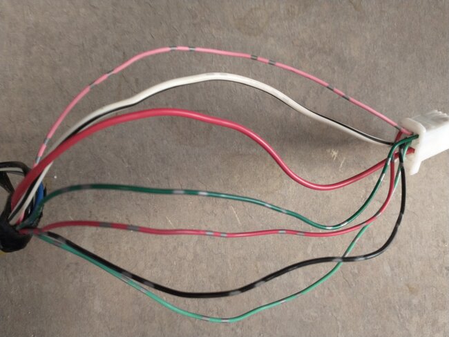
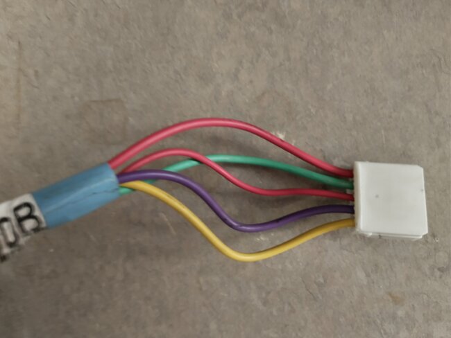
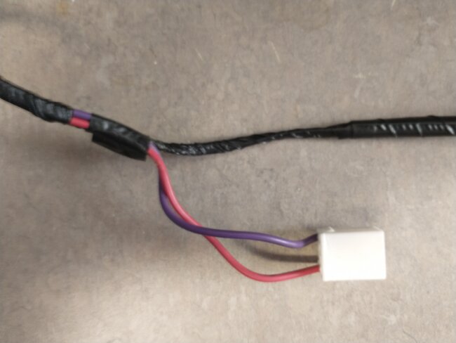
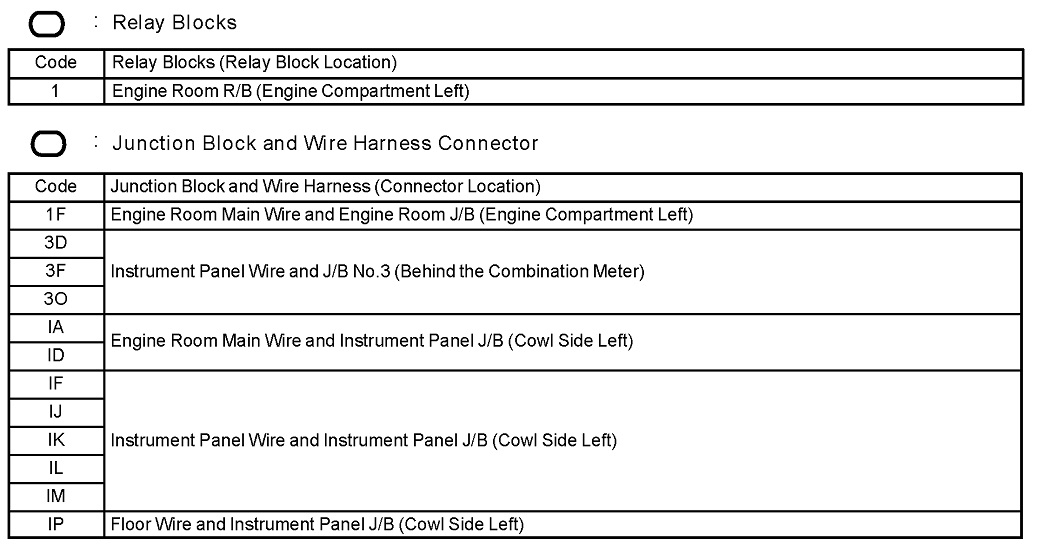
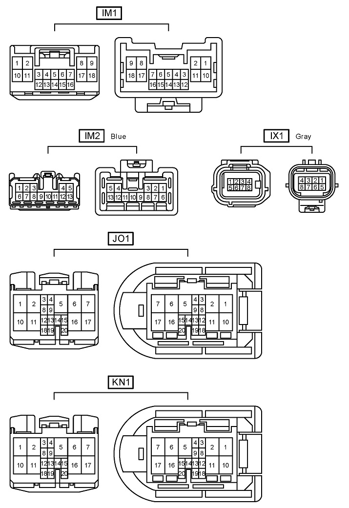
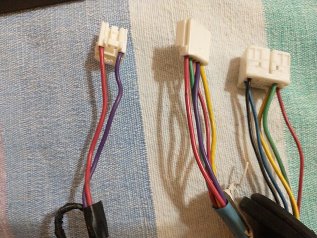
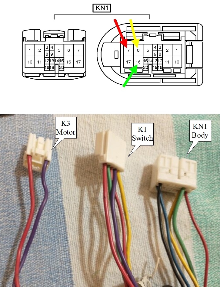
" The main connection on this harness has five wires on it. A black wire, a blue wire, a yellow wire, a green wire, and a red wire".

That's connector "KN1".

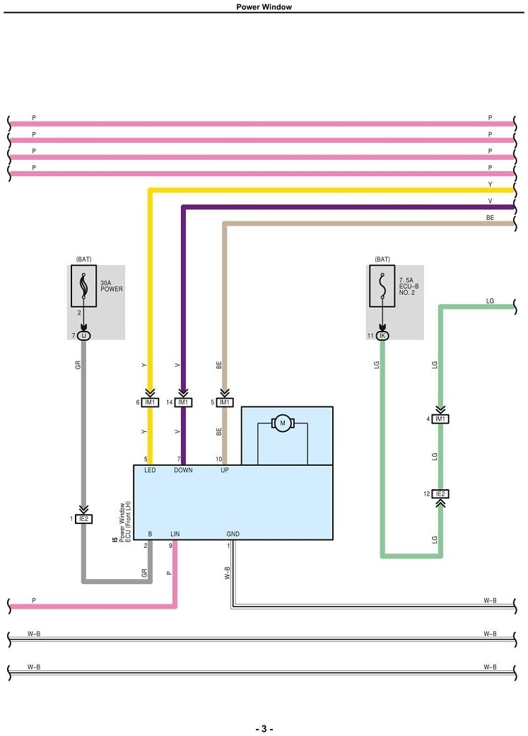
"The window up and down switch connection has two wires to it, a purple wire and the OTHER red wire red wire (re: the above two red wires). Those two wires have continuity from the window motor connection to the window up and down switch"

The third diagram shows what you just measured. The red arrows are pointing to the red wire at the motor and at the switch. Same with the purple arrows for the purple wire.

A lot of confusion is from that red wire to the motor. It would have been nice if they had used any other color. This is where you went off the rails.

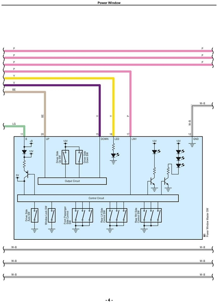
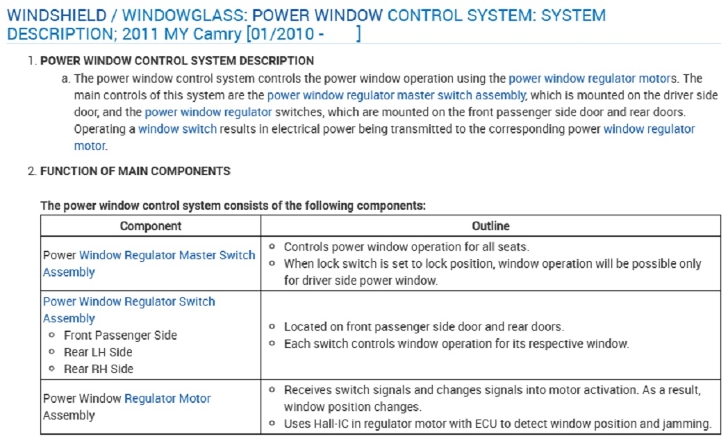
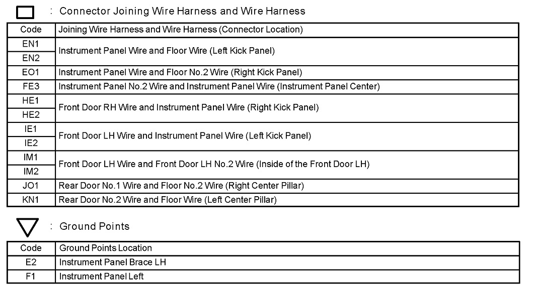
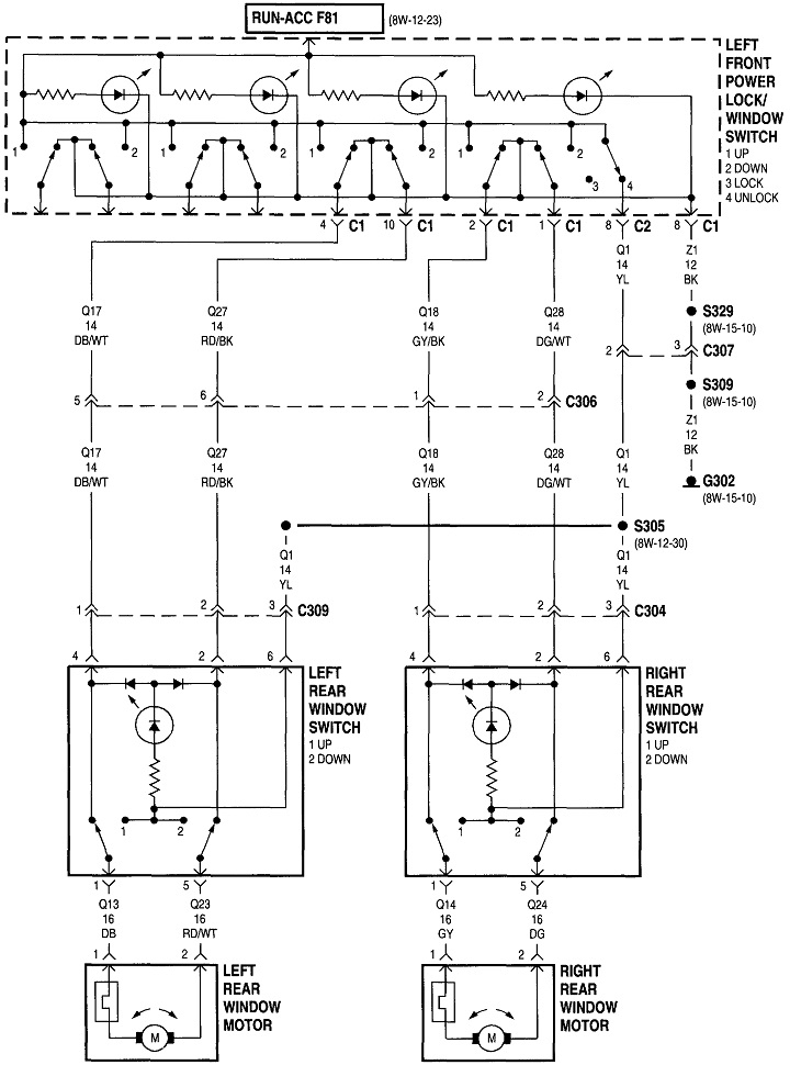
Rather than comment on each test you did, it might make more sense with the fourth diagram. They didn't show the driver's switch for your model, so these are for a '98 Jeep. Other than the little lights in the switches, this is a very basic and common circuit.

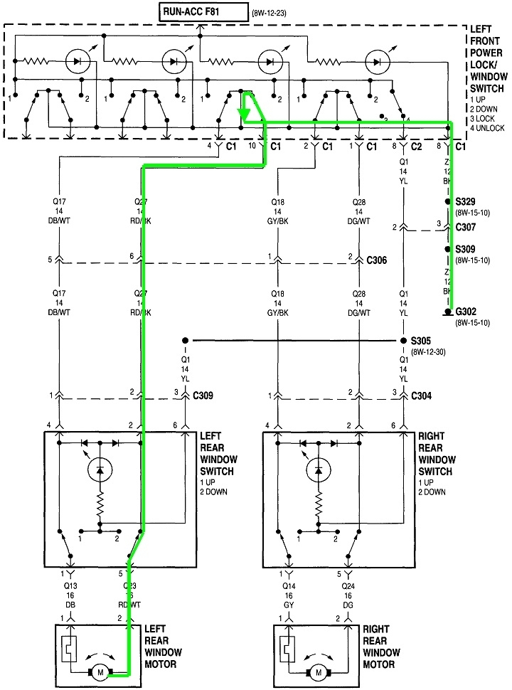
In the fifth diagram, I added the green circuit that matches the red motor wire of your circuit. The important point in these diagrams is all of the switches are released.

Starting at the motor, follow the wire through the left rear "down" switch, through two connectors to the driver's door and switch, through the driver's "LR down" switch, back through the hinges and another connector, then to ground on the body.

In the sixth diagram, the blue circuit follows a similar path through the left rear "up" switch, through two connectors, to the driver's door and switch, through the driver's "LR up" switch, then to ground just like the red circuit.

Everywhere you measure in these two circuits will have continuity to ground, but only when everything is plugged in. This is why this circuit confuses so many people. Everything seems to be shorted.

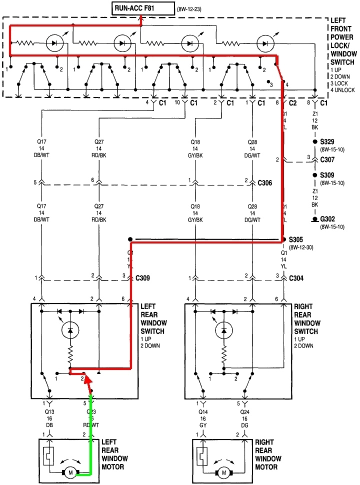
The magic starts when one switch is pressed in diagram seven. The red line shows the 12 volt supply circuit. Follow this through the lockout switch at the far right of the driver's switch, then out to the three passenger switches. In the left rear switch, the "down" switch is pressed. Note that the "up" switch is still released and is still grounded. The "down" switch has moved away from the ground contact, and is touching the 12 volt contact. That 12 volts appears on one motor terminal. The other motor terminal is still grounded. Current always must have a complete path from and back to the battery to flow. The green line shows the positive half of the circuit, and the blue line in the sixth diagram shows the ground side. The window rolls down.

Moving the switch the other way leaves the "down" switch released and grounded, but puts the 12 volts on the left side of the motor. The motor runs the other way. This same switching can be done at the driver's switch.

Another important point is regardless which switch is pressed, there are four sets of contacts current must flow through for the motor to run. That's the one pressed switch and the three released switches. Also, the part of the switch with the ground contact can be arced or pitted causing the circuit to not work. That means either one can cause the problem when either one is pressed.

To say that a less confusing way, the window could work both ways from the driver's switch, but the "down" function is dead from the left rear switch, but it's the driver's switch that is at fault. The working switch can be the bad one.

When trying to run the window down, if you connect the battery with everything connected, remember both wires go to ground through the four released switches. That puts a dead short across the battery, and lots of sparks and excitement. You have to break the circuit someplace so that short isn't there.

Getting back to your circuit, you already have everything disconnected, so those wires aren't grounded, shorted, or connected. You're free to connect the battery. Since you were able to get to the "K3" motor connector, you can connect the battery's positive and negative wires to those two terminals on the motor if you can get to them. Change the polarity if the motor tries to run the wrong way.

Another way is to plug the "K3" connector back into the motor, then connect the battery wires to the green and yellow wires in the "KN1" connector. You'll be mimicking what the driver's switch does when a switch is pressed. You can also use the red and purple wires. The switch doesn't have to be plugged in to use the red and purple wires. It does when using the green and yellow wires.

There's no actual ground wire with the "KN1" body connector unplugged. The red 12 volt wire coming from the fuse can be used, but doing so is overly-complicated because you would have to press a switch and move the other wire around. If the goal is just to get the window down so you can work on the door, it's far easier to use the green and yellow or the red and purple wires.
Was this
answer
helpful?
Yes
No
+1
Thursday, May 11th, 2023 AT 2:02 PM
Tiny
COLLIN WILLIAMS
  • MEMBER
  • 10 POSTS
I wanted to touch base again to thank you for your help with the harness. I was able to get the old door close enough to the car connection in the door to connect it and get that window down with the window switch. The replacement door. Although the window was stuck in the up position I was actually able to remove the motor with it up. The issue would have been had I needed to replace the window. For that I would have had to get the motor in the fully down position. Since I switched everything out in the doors the motor I needed to be down was the one I was fortunate enough to get down.
I wanted to thank you for all of your help with this situation. You were more detailed and thorough that one would ever have expected. Thank you again!
CW
Was this
answer
helpful?
Yes
No
Thursday, May 25th, 2023 AT 5:30 PM
Tiny
CARADIODOC
  • MECHANIC
  • 33,737 POSTS
Very happy to hear you solved this. Please come back to see us when you need more of my wondrous wisdom!
Was this
answer
helpful?
Yes
No
+1
Thursday, May 25th, 2023 AT 5:59 PM

Please login or register to post a reply.

Sponsored links