Wiring break in brake/turn signal lines to rear, wiring diagram needed?

Tiny
KGBS
  • MEMBER
  • 2008 CADILLAC ESCALADE
  • 6.2L
  • V8
  • 2WD
  • AUTOMATIC
  • 174,000 MILES
Hi, I'm looking to find a wiring chart for the brake/turn signal lines for the vehicle listed above. Lights in the back went out one side at a time and I've tested the diodes and they work so it's a bust in the wiring. I just need to know where they come out of and the color of each wire - left and right. Thank you.
Monday, January 23rd, 2023 AT 3:25 PM

9 Replies

Tiny
JACOBANDNICKOLAS
  • MECHANIC
  • 108,192 POSTS
Hi,

If you look below, I attached the entire wiring schematic for the exterior lighting circuit. Take a look through them and let me know if they help.

Also, the schematic was two pages. I had to cut each page in half to make it readable for you. I did overlap them so you can follow from one to the next.

Here is a link you may find helpful as well:

https://www.2carpros.com/articles/how-to-check-wiring

Let me know if this helps and if you have questions.

Take care,

Joe

See pics below.

Was this
answer
helpful?
Yes
No
Monday, January 23rd, 2023 AT 6:35 PM
Tiny
KRASSIMIR STOICHEV
  • MEMBER
  • 6 POSTS
Joe,

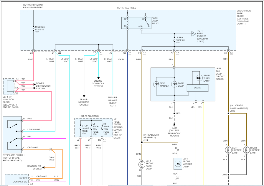
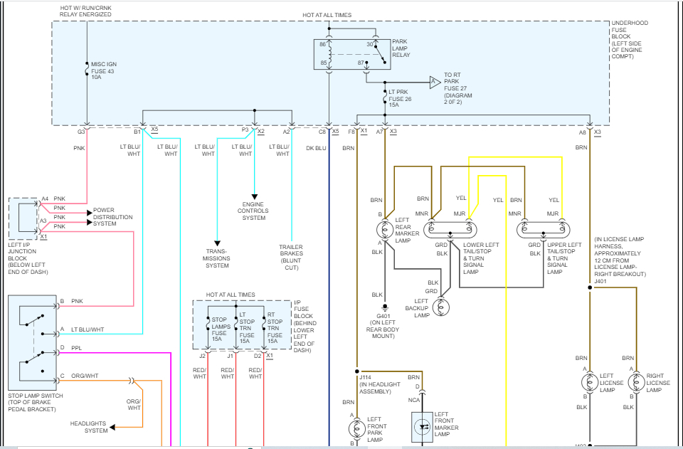
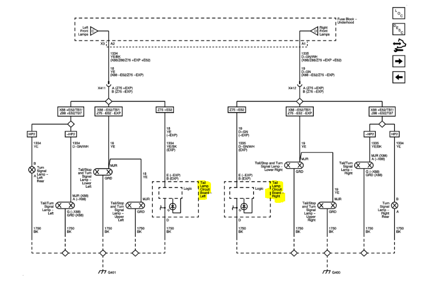
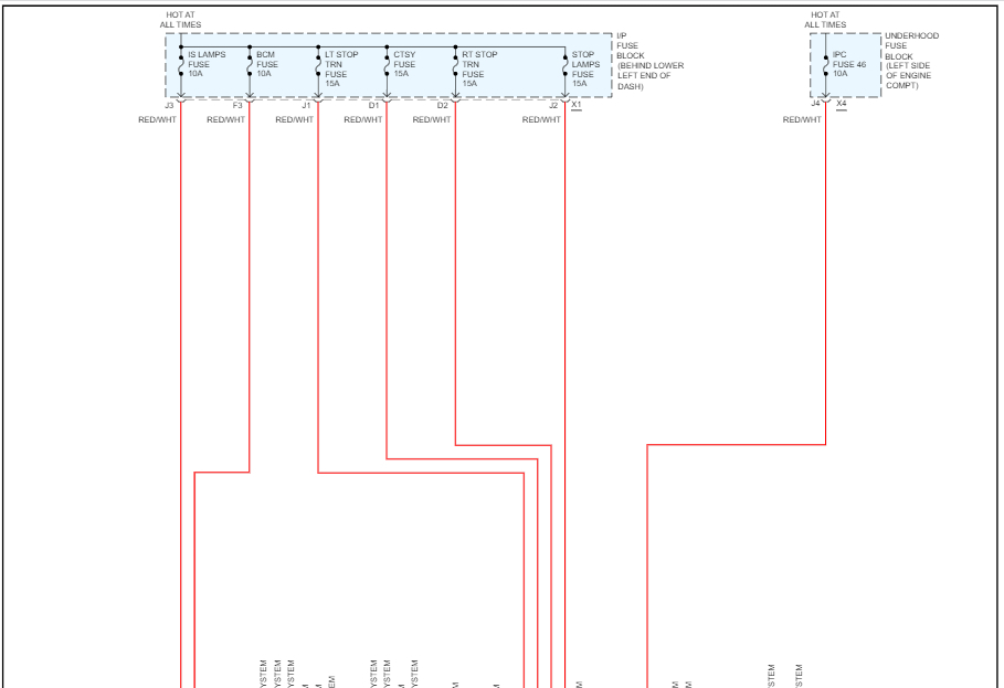
Thank you so much, that was exactly what I needed. I never thought those circuits would be fused but they are - apparently, for the electronics inside the taillights - and I went to check the fuses first. Unfortunately, they are good so it's something else. From your diagram I see that each taillight has a built-in circuit board - that one I could have easily guessed alright - but:

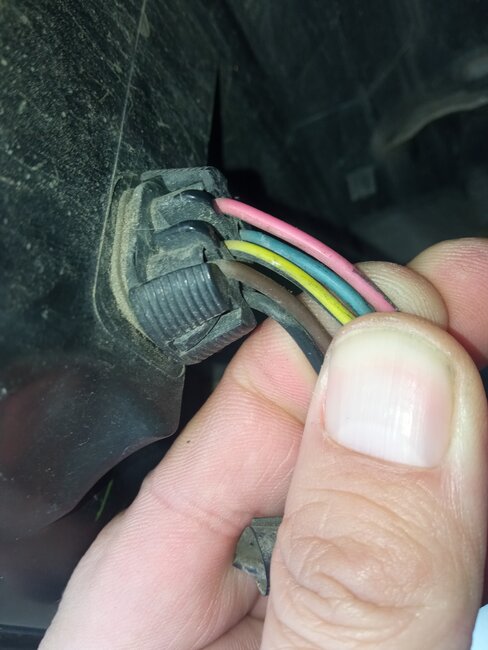
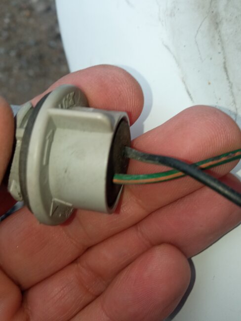
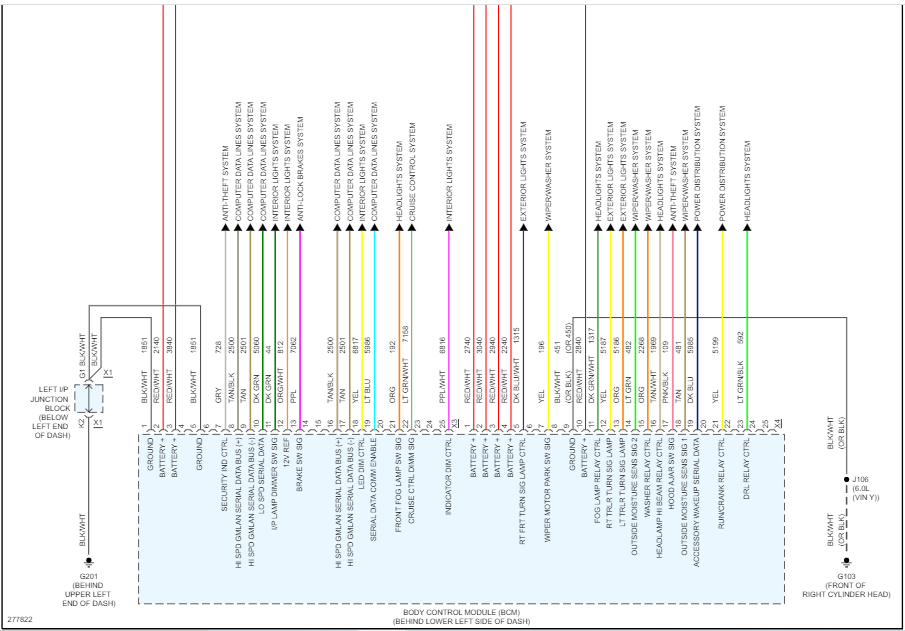
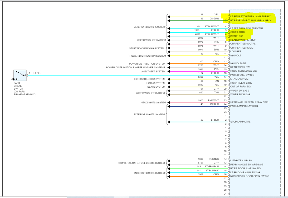
I can't really recognize the wiring that goes in and out of the taillights. On both sides of the car, I have the same set of 5 colors and if I do a voltmeter test, I can see which wire is for the brake (stop light) and which is for the turn signal. This is not what I see on your diagram.

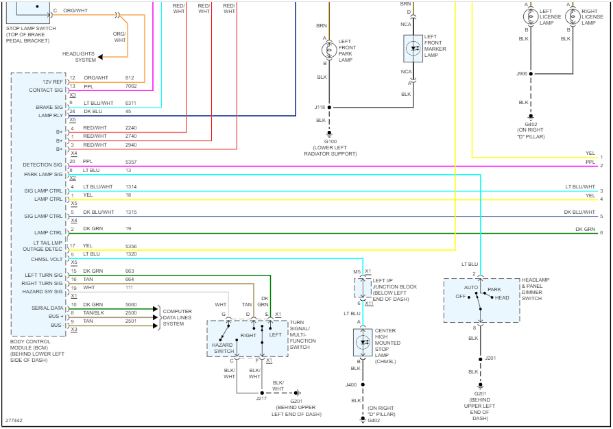
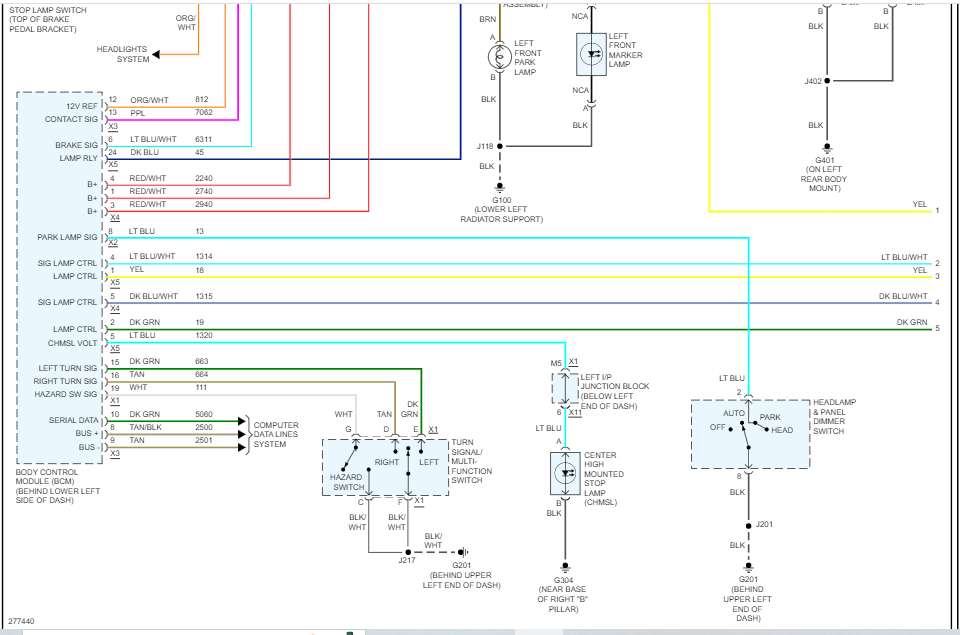
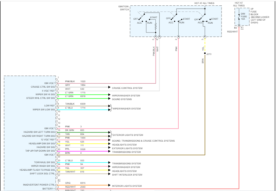
So, if there's a common signal that gets distributed inside the taillight circuit board to different functions, I have the taillights working, only the stop lights/turn signals are not. This brings me to the theory that the issue could be in the fuses wiring because those fuses are the only element in the whole chain that matches the problem exactly. Again, fuses are good so I'm thinking of measuring voltage at them as well as the corresponding pins on the BCM.

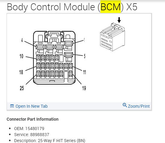
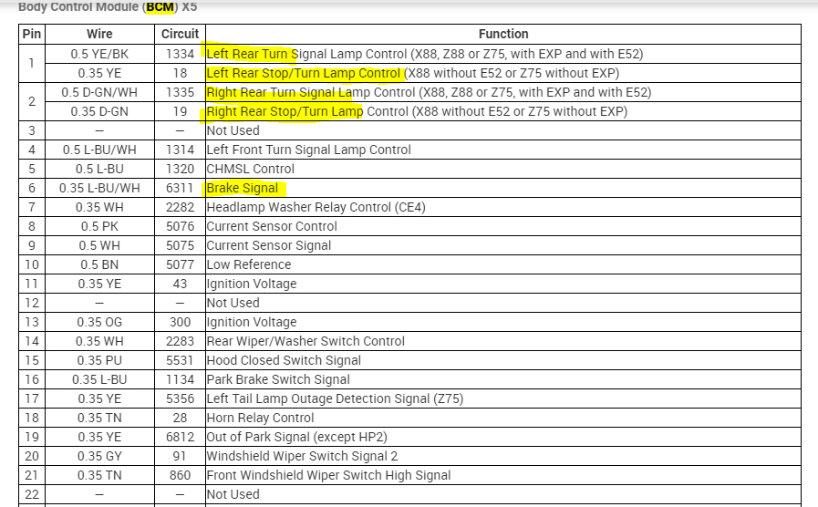
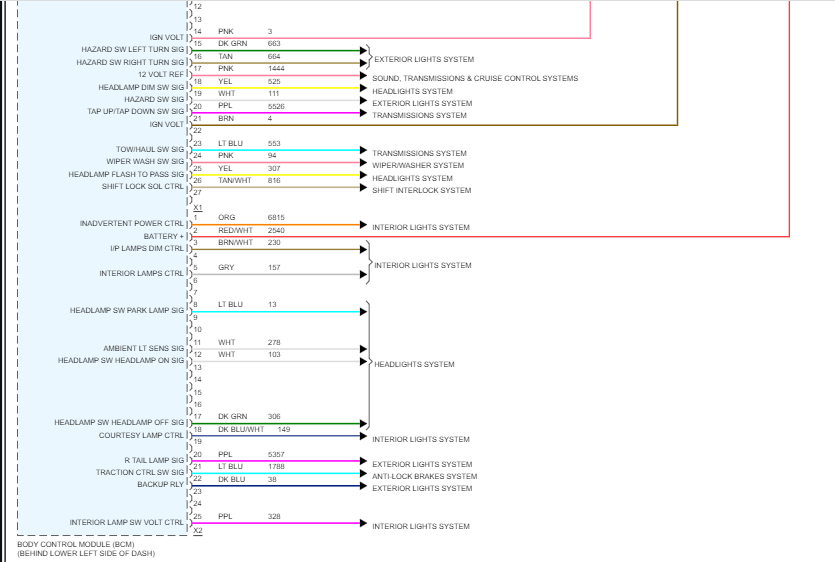
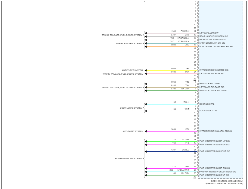
So, my question to you is this: I see the pins are #1 and #3; would you happen to have the pinout or even just the numbering on the BCM? I don't even know where it's located yet but I'll find it, I just need to know which pins to measure at.

If you have any other thoughts; please feel free to share them.

Thank you.
Was this
answer
helpful?
Yes
No
Tuesday, January 24th, 2023 AT 6:59 AM
Tiny
JACOBANDNICKOLAS
  • MECHANIC
  • 108,192 POSTS
Hi,

I have a question. The wiring schematic shows an option related to the schematics. It indicates two different schematics for a one-piece liftgate and one without a one-piece liftgate.

What I attached above is for a one-piece liftgate. Is that what you have? That could be why the wiring is off.

Below, I attached the schematics for one without a one-piece liftgate. Check to see if that makes a difference. I need to know because this will change the BCM wiring.

Let me know.

Joe
Was this
answer
helpful?
Yes
No
Tuesday, January 24th, 2023 AT 1:17 PM
Tiny
KGBS
  • MEMBER
  • 24 POSTS
Joe,

Thank you for the update but no, it's a one-piece liftgate and the second set of schemes is even further from the truth. Please find attached the following photos:

* First two pics are of the actual taillight
* Next three pics are stock photos of the harness, one is captioned

Here's an eBay listing of the real thing with large pics for clarity:

https://www.ebay.com/itm/275196420129?hash=item4012fc2021:g:sg0AAOSwX3hiI CS&amdata=enc%3AAQAHAAAAwO7T%2BmGwJqplOCz59SX%2BdGkRDWQ9Lw%2BZxX%2BWqhzyx7%2BPicZF2P5xiEQ3ULJP7AmdNHxWYYNC68OkZ3cIDLU3YPA85h%2FBbv1%2BC7bZM%2FiVrZM%2BUiTjvH%2B%2F63uvKzNwmWwP99tdi3QodCNL4LrE%2B%2Fm0oa9Ow2%2Fbh2D8T4xEDInm7m7nkReJr28hl2kh3zaMAen86LXTVRw0F%2BmMAIW2F8MsS%2FpVNLrajUqv6598CD%2FrosXxlSnmI9n0RtfjBUEkDUYY0A%3D%3D%7Ctkp%3ABk9SR6rD25K9YQ

Please copy the whole string because in the hyperlink it gets cut.

So, I really need to match the 6-lead connector's colors to a wiring diagram. So far, I've been unable to do that in what you've sent me. Let me once again say that we're talking about a 2008 Cadillac Escalade Base (model doesn't matter anyway, they're all the same in the taillights.)

Thank you for your assistance.
Was this
answer
helpful?
Yes
No
Wednesday, January 25th, 2023 AT 9:16 AM
Tiny
JACOBANDNICKOLAS
  • MECHANIC
  • 108,192 POSTS
Hi,

I dug up a factory wiring schematic. It appears the same as what I originally sent. Take a look through it and let me know your thoughts. Also, are you getting power to any of the rear lamps if you have the brakes on or the turn signals?

If you are getting power, then I have a feeling it may be the internal circuit board/logic module.

Let me know if this schematic is closer to what you have.

Take care,

joe

See pic below.
Was this
answer
helpful?
Yes
No
Wednesday, January 25th, 2023 AT 7:58 PM
Tiny
KRASSIMIR STOICHEV
  • MEMBER
  • 6 POSTS
Hi again,

No, I'm not getting power in the brake/turn lead on any side, left or right. This is the reason to ask for diagrams, so I know how to follow those leads back to the BCM.

The new scheme is again not the answer because I don't have upper right and lower right - or left. It's a one-piece taillight so we're basically not looking at the correct diagrams.

Don't worry about it, I'll figure it out somehow. Thank you for your time.
Was this
answer
helpful?
Yes
No
Thursday, January 26th, 2023 AT 1:43 AM
Tiny
JACOBANDNICKOLAS
  • MECHANIC
  • 108,192 POSTS
Hi,

I'm not sure why everything I have is different. I actually checked the different packages, and they were the same as well.

If you have a chance, let me know what you find. I am really interested in knowing what is going on. LOL

Take care of yourself and again, let me know if there is anything I can do to help.

Joe
Was this
answer
helpful?
Yes
No
Thursday, January 26th, 2023 AT 1:31 PM
Tiny
KGBS
  • MEMBER
  • 24 POSTS
Joe, could you please send me the Body Control Module diagram so I can try to make some sense of it? I'm browsing the forums and it's now pretty clear that 2 out of the 5 leads going into the LED block are not used - the yellow and pink ones. That leaves us with Blue (stop/turn), Brown (side marker) and Black (ground) to be located on the diagram. Let me see what I can figure out if I start at the other end.

Also, a pic of the BCM connector for the pinout and pin numbering would help a lot. If you don't have it, I'll try to guess it by the wire colors. Let's start with the BCM diagram anyway.

Thank you.
Was this
answer
helpful?
Yes
No
Monday, January 30th, 2023 AT 9:28 AM
Tiny
JACOBANDNICKOLAS
  • MECHANIC
  • 108,192 POSTS
Hi,

I attached the pinout from the BCM below for you. Please take a look at it and let me know if I got what you were looking for. (Pics 1-3)

The remaining pics are the schematic to the BCM. If you look at pic 8, I feel that it will be of most interest to you.

Let me know if this helps or if you have questions.

Take care,

joe

See pics below.
Was this
answer
helpful?
Yes
No
Monday, January 30th, 2023 AT 7:01 PM

Please login or register to post a reply.

Sponsored links