Thank you.
Below is the description and I attached the flow chart with a wiring diagram. Most of the time, it is due to carbon build up in the head.
Roy
CIRCUIT DESCRIPTION
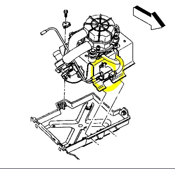
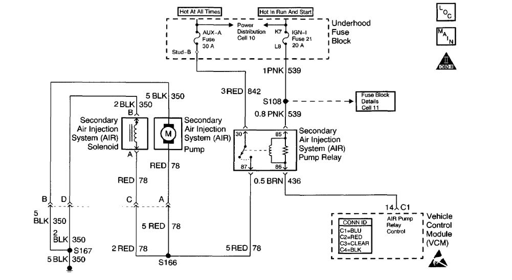
An AIR Pump is used on this vehicle to lower tail pipe emissions at start-up. The VCM supplies a ground to the AIR Pump Relay, which energizes the AIR Pump and the AIR Solenoid.
When the AIR Pump is enabled, the VCM monitors the HO2S voltage. If the HO2S voltages go below a calibrated threshold value, the VCM interprets this as an indication that the AIR System is operational.
When the AIR Pump is disabled, the VCM monitors the HO2S voltages. The HO2S voltages should increase above a calibrated threshold value and switch normally.
If the VCM did not sense more than a predetermined amount of HO2S rich switches, a malfunction will be reported.
The VCM will activate the AIR Pump during closed loop operation. When the AIR System is activated, the VCM will monitor the HO2S voltages and short term fuel trim values for both banks of the engine. If the AIR System is operating properly, the HO2S voltages should go low and the short term fuel trim should go high.
The VCM checks that the HO2S voltages return to above a rich threshold when the AIR Pump is disabled.
If the VCM determines that the HO2S voltages for both banks did not respond as expected during the tests, DTC P0410 will set. If only one sensor responded, the VCM will set either a DTC P1415 or P1416 to indicate on which bank the AIR System is inoperative.
CONDITIONS FOR RUNNING THE DTC
^ No MAF DTCs
^ No MAP DTCs
^ No IAT DTCs
^ No ECT DTCs
^ No TP Sensor DTCs
^ No HO2S DTCs
^ No VSS DTCs
^ No system voltage DTCs
^ No Fuel Trim DTCs
^ No Misfire DTCs
^ No CCP DTCs
^ MAF is less than 25 grams per second Engine load is less than 34 percent
^ Power Enrichment Mode is not active
^ DFCO (Decel Fuel Cutoff Mode) is not active
^ Convertor Over Temperature not active
^ Engine run time after Closed Loop is more than 20 seconds
^ Air/Fuel Ratio is 14.7:1
^ Fuel Trim counts between 124-132
^ Engine speed above 550 RPM
^ ECT is between 80-107°C (176-225°F)
^ System voltage is more than 11.7 volts
^ IAT is more than 2°C (36°F)
CONDITIONS FOR SETTING THE DTC
HO2S voltage is more than 0.222 volt (222 mV) for more than 1 second when AIR pump is enabled
ACTION TAKEN WHEN THE DTC SETS
^ The control module illuminates the Malfunction Indicator Lamp (MIL) if a failure is detected during 2 consecutive key cycles.
^ The control module sets the DTC and records the operating conditions at the time the diagnostic failed. The failure information is stored in the scan tools Freeze Frame and Failure Records.
CONDITIONS FOR CLEARING THE MIL/DTC
^ The control module turns OFF the MIL after 3 consecutive drive trips when the test has Run and Passed
^ A history DTC will clear if no fault conditions have been detected for 40 warm-up cycles. A warm up cycle occurs when the coolant temperature has risen 22°C (40°F) from the startup coolant temperature and the engine coolant reaches a temperature that is more than 70°C (158°F) during the same ignition cycle.
^ A scan tool can clear the DTCs.
DIAGNOSTIC AIDS
Low AIR System volume may cause a DTC P1415, P1416 or an intermittent complaint. Also check for the following conditions:
^ Pinched, kinked or restricted AIR pipes, hoses or fittings
^ Leaks, holes, loose fittings or hoses
^ Restricted or obstructed AIR pump inlet
^ Leaks or restrictions in the vacuum hoses for the AIR Shut Off Valve.
An AIR supply hose that is melted before the check valve could indicate exhaust gas back-flow past the check valve.
An intermittent may be caused by any of the following conditions:
^ A poor connection
^ Rubbed through wire insulation
^ A broken wire inside the insulation
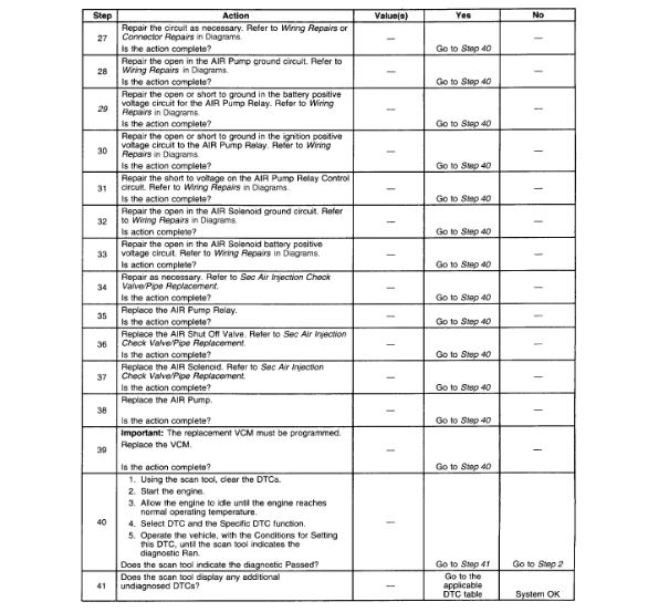
Thoroughly check any circuitry that is suspected of causing the intermittent complaint. Refer to Testing for Intermittent and Poor Connections in Diagrams. If a repair is necessary, then refer to Wiring Repairs or Connector Repairs in Diagrams.
TEST DESCRIPTION
Number(s) below refer to the step number(s) on the Diagnostic Table.
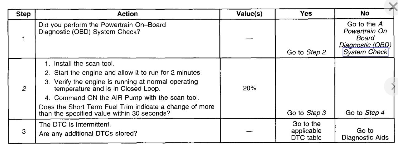
2. This step will determine if the AIR System is functioning correctly.
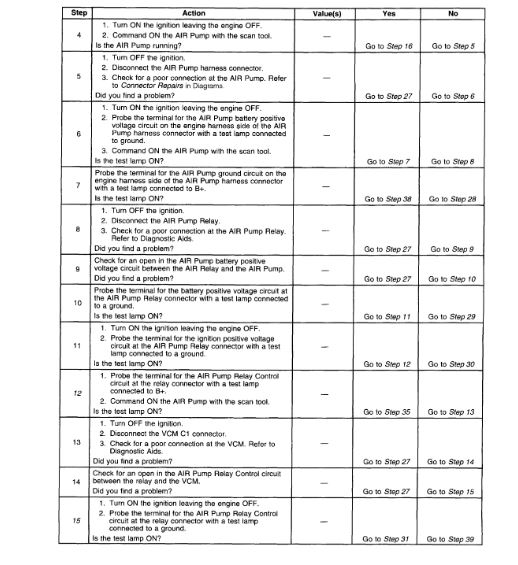
12. This step will determine if the VCM is capable of controlling the AIR Pump Relay.
15. This step is to check for a short to voltage on the control circuit.
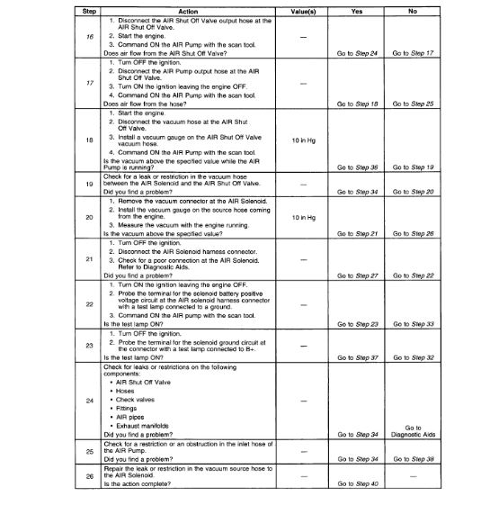
16. The engine must be running for this test to ensure a vacuum supply to the system.
17. This step will determine if the AIR Pump is capable of producing airflow.
29. An open fuse for the battery feed circuit could be caused by a short to ground in the components operated by the relay. Also check the wiring in the circuits on the switched side of the relay. Refer to Diagnostic Aids.
Images (Click to enlarge)
Jul 5, 2019 at 3:15 PM