Where a connector should be connected

Tiny
MINOURA
  • MEMBER
  • 1994 GEO PRIZM
  • 1.6L
  • 4 CYL
  • 2WD
  • 160,000 MILES
When a air filter container was removed, one connector was accidentally removed.
This is not the air temperature sensor or the backup sensor connector.

The connector is connected to the red-black and white-black wire pair that branches from the wire bundle whose four wires are connected to the throttle position sensor (TPS) located at the entry point of the intake air manifold.

Where should this connector be connected?
Wednesday, June 12th, 2019 AT 6:25 PM

4 Replies

Tiny
SCGRANTURISMO
  • MECHANIC
  • 4,897 POSTS
Hello,

This sounds like it could possibly be the connector to your vehicle's Idle Air Control valve (IAC). In the diagrams down below I have included a engine wiring diagram, component connector diagram with callout, and the location of the component on your vehicle. Please go through the information and get back to us with what you are able to find out.

Thanks,
Alex
2CarPros
Was this
answer
helpful?
Yes
No
Wednesday, June 12th, 2019 AT 11:41 PM
Tiny
MINOURA
  • MEMBER
  • 6 POSTS
Thank you for your quick reply.I will look at the location you mentioned.

However. The connector is for two pins. As your overview picture matches our car, I will look at the parts 10 through 17.

BTW, the cable of the connector has a fastener that can be attached to a small hole on a metal sheet.
Was this
answer
helpful?
Yes
No
Thursday, June 13th, 2019 AT 1:28 AM
Tiny
MINOURA
  • MEMBER
  • 6 POSTS
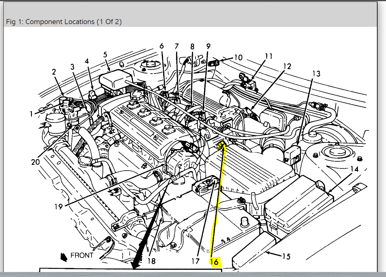
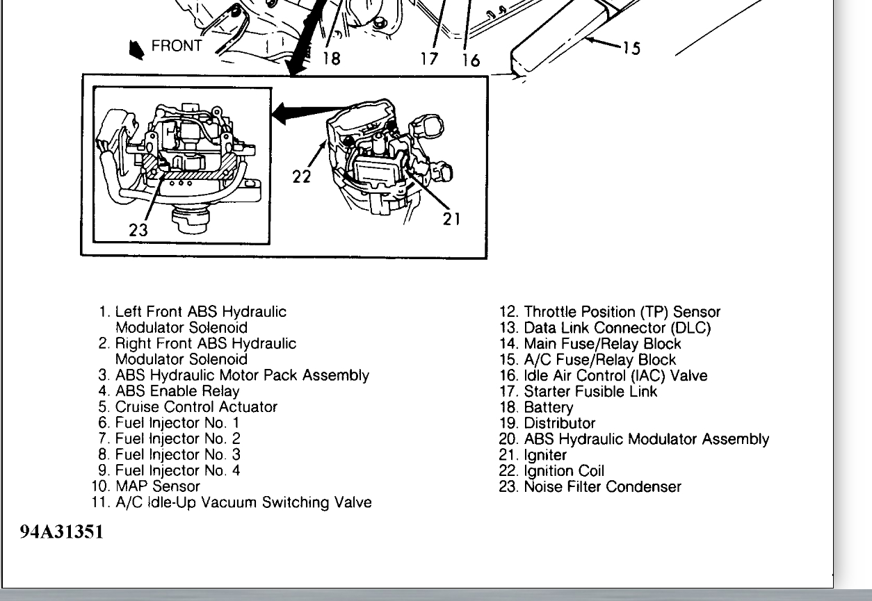
I carefully looked at the parts 10 through 17.

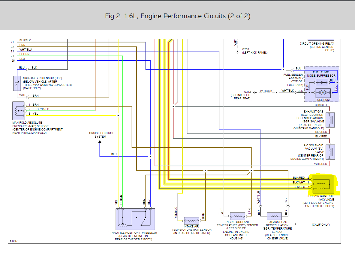
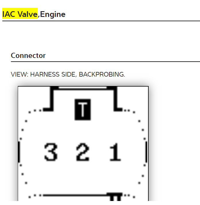
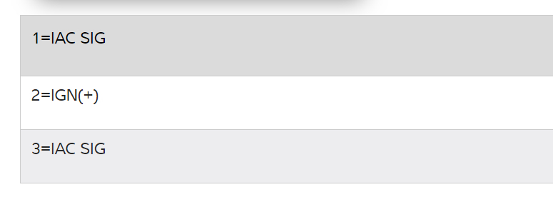
The 3-pin connector for the Idle Air Control valve (IAC) is correctly installed.

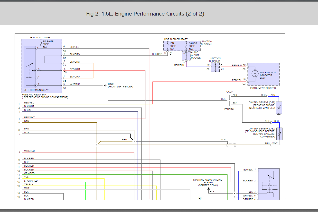
Although our car does not have A/C, the (15) A/C Fuse/Relay Block is provided. However, the (11) A/C Idle-Up Vacuum Switching Valve is not.

I looked at information posted for this part by AutoZone.

https://www.autozone.com/repairguides/Toyota-Celica-1994-1998-Repair-Guide/ELECTRONIC-ENGINE-CONTROLS/AC-Idle-Up-System/_/P-0900c15280074e63

The connector for this part is for 2-pins, and the method of wire installation shown in Fig.9 matches the fact that the tube covering the wires can be fastened to the firewall.

My conclusion is that the connector is not used.

The manual by Hayes I have includes a wiring diagram for A/C, but it does not show the A/C Idle-Up Vacuum Switching Valve.

The picture showing the part layout helped me greatly. Thank you very much.
Was this
answer
helpful?
Yes
No
Thursday, June 13th, 2019 AT 9:19 AM
Tiny
KEN L
  • MASTER CERTIFIED MECHANIC
  • 42,883 POSTS
SCWICKEDSTANG is one of our best! Nice work, we are here to help, please use 2CarPros anytime.
Was this
answer
helpful?
Yes
No
Monday, June 17th, 2019 AT 12:58 PM

Please login or register to post a reply.

Sponsored links