Sure, here is how to change out the bearing hub with torque specs. Please check out the images below as well. Instead of using a special tool to help undo the CV axle nut just leave the car on the ground and then loosen the nut and raise the car after that.
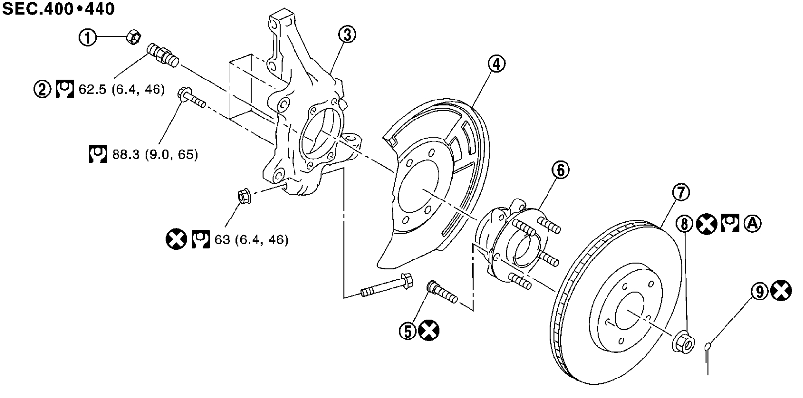
FRONT WHEEL HUB AND KNUCKLE
Removal and Installation
REMOVAL
1.Remove tires with power tool. See: Wheels and Tires > Removal and Replacement > Exploded View.
2.Remove wheel sensor. See: Wheel Speed Sensor > Removal and Replacement > Removal And Installation.
3.Remove lock plate from strut assembly. See: Brake Hose/Line > Removal and Replacement > Exploded View.
4.Remove caliper assembly. Hang caliper assembly not to interfere with work. See: Brake Caliper > Removal and Replacement > Removal And Installation.
CAUTION:
Never depress brake pedal while brake caliper is removed.
5.Remove disc rotor.
- Put matching marks (A) on the wheel hub assembly and the disc rotor before removing the disc rotor.
- Never drop disc rotor.
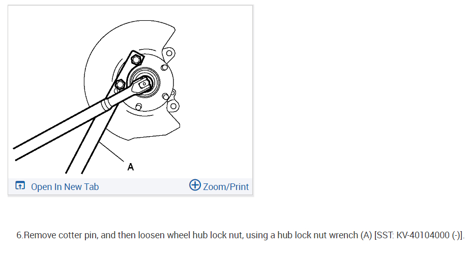
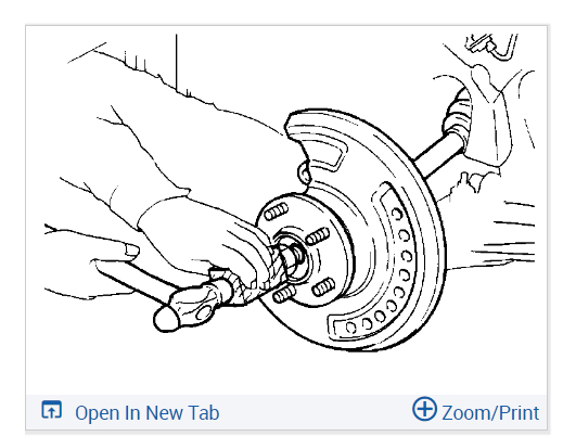
6.Remove cotter pin, and then loosen wheel hub lock nut, using a hub lock nut wrench (A) [SST: KV-40104000 (-)].
7.Patch wheel hub lock nut with a piece of wood. Hammer the wood to disengage wheel hub assembly from drive shaft.
NOTE:
Use suitable puller, if wheel hub assembly and drive shaft cannot be separated even after performing the above procedure.
8.Remove wheel hub lock nut.
9.Remove strut assembly from steering knuckle. See: Suspension Strut / Shock Absorber > Removal and Replacement > Removal And Installation.
10.Remove drive shaft from wheel hub assembly. Hang drive shaft not to interfere with work.
CAUTION:
- Never place drive shaft joint at an extreme angle. Also be careful not to overextend slide joint.
- Never allow drive shaft to hang down without support for joint sub-assembly, shaft and the other parts.
11.Remove wheel hub assembly and splash guard from steering knuckle.
12.Separate steering outer socket from steering knuckle. See: Steering Gear > Removal and Replacement > Removal And Installation.
13.Separate steering knuckle from transverse link.
14.Remove stopper cap and stopper bolt from steering knuckle.
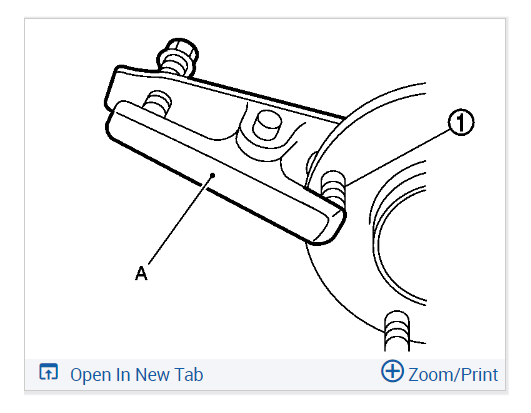
15.Remove hub bolts (1) from wheel hub assembly, using the ball joint remover (A) (commercial service tool).
CAUTION:
- Remove hub bolt only when necessary.
- Never hammer the hub bolt to avoid impact to the wheel hub assembly.
- Pull out the hub bolt in a direction perpendicular to the wheel hub assembly.
16.Perform inspection after removal. See: Wheel Hub > Removal and Replacement > Inspection.
INSTALLATION
Note the following, and install in the reverse order of the removal.
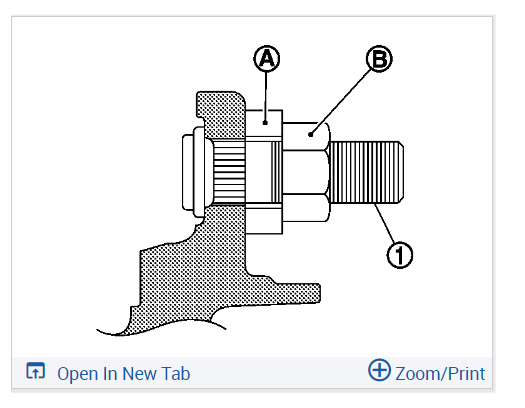
- Place a washer (A) as shown in the figure to install the hub bolts (1) by using the tightening force of the nut (B).
CAUTION:
- Check that there is no clearance between wheel hub assembly, and hub bolt.
- Never reuse hub bolt.
- Never reuse steering knuckle and transverse link fixing nut.
- Clean the matching surface of wheel hub lock nut and wheel hub assembly.
CAUTION:
Never apply lubricating oil to these matching surface.
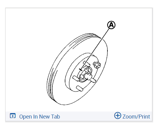
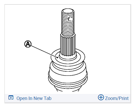
- Clean the matching surface of drive shaft, wheel hub assembly.
And then apply paste [service parts (440037S000)] to surface (A)
of joint sub-assembly of drive shaft.
CAUTION:
Apply paste to cover entire flat surface of joint sub-assembly of drive shaft.
Amount paste: 1.0 - 3.0 g (0.04 - 0.10 oz)
- Use the following torque range for tightening the wheel hub lock nut.
CAUTION:
- Since the drive shaft is assembled by press-fitting, use the tightening torque range for the wheel hub lock nut.
- Be sure to use torque wrench to tighten the wheel hub lock nut. Never use a power tool.
- Never reuse wheel hub lock nut.
NOTE:
Wheel hub lock nut tightening torque does not over torque for avoiding axle noise, and does not less than torque for avoiding looseness.
- Align the matching marks that have been made during removal when reusing the disc rotor.
- When installing a cotter pin, securely bend the basal portion to prevent rattles.
CAUTION:
- Never reuse cotter pin.
- Bend cotter pin at the root sufficiently to prevent any looseness.
- Perform the final tightening of each of parts under unladen conditions, which were removed when removing suspension component.
- Perform inspection after installation. See: Wheel Hub > Removal and Replacement > Inspection.
Check out the images (below). Let us know if you need anything else.
Images (Click to enlarge)
Mar 31, 2024 at 7:06 PM