Hi,
Here is what I believe is happening:
First, the idea that you need to press the throttle for it to start indicates to me that the vehicle is flooded. When you press the pedal on this vehicle, it shuts down the injectors to clear a flooded engine.
Next, the idea that you saw smoke indicates a rich fuel mixture. Was the smoke black? If it was, that supports what I said about a flooded engine.
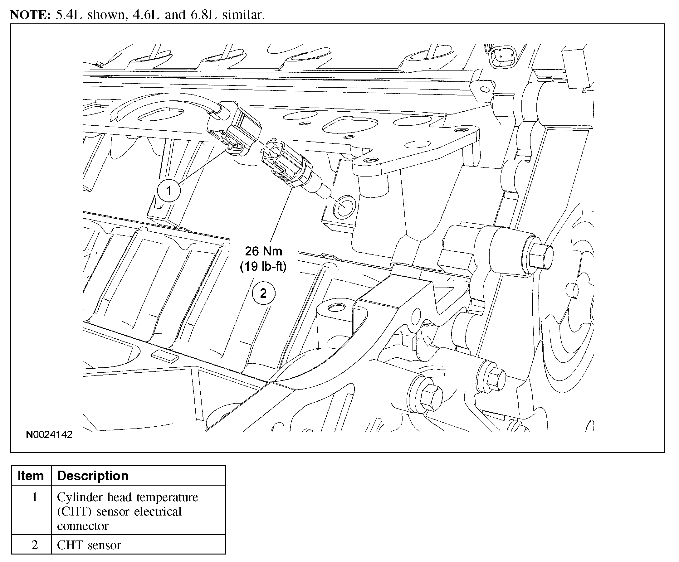
The idea that the temp gauge isn't working is the final part. The cylinder head temp sensor is used by the computer to determine the air fuel mixture delivered to the engine. If it is stuck on cold, it could be telling the computer it's -40°F which would demand a very rich fuel mixture to run the engine. I suspect you are not in those conditions.
_______________
Here is what I suggest: The easiest thing to do is to get a live data scan tool and see what the temp sensor is indicating. The temp should be close to the ambient temp outside. If it stays cold, replace the sensor.
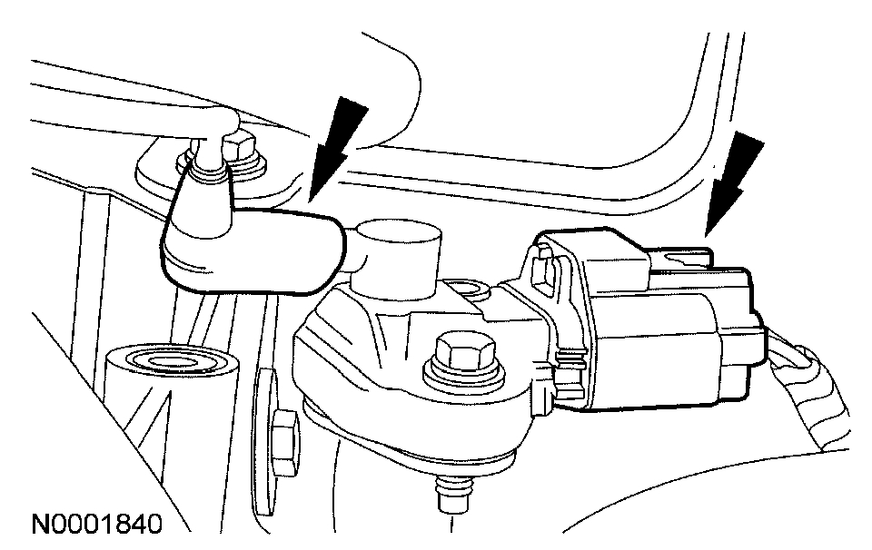
I attached a pic of it's location (pic 1). It may require the removal of the intake manifold to access. You will need to check if it is accessible on a van.
If you need to remove the intake, here are the directions. The remaining pics correlate with the directions. I don't recommend going to this much trouble unless you confirm the sensor is bad.
____________________________________________
2007 Ford Truck E 150 V8-5.4L
Removal and Installation
Vehicle Engine, Cooling and Exhaust Engine Intake Manifold Service and Repair Procedures Removal and Installation
REMOVAL AND INSTALLATION
Intake Manifold - 5.4L
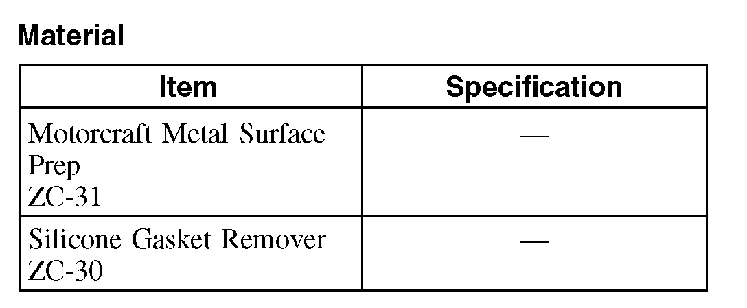
Material
pic 2
pic 3
pic 4
Removal
WARNING: Do not smoke or carry lighted tobacco or open flame of any type when working on or near any fuel-related component. Highly flammable mixtures are always present and may be ignited. Failure to follow these instructions may result in personal injury.
WARNING: Fuel in the fuel system remains under high pressure even when the engine is not running. Before servicing or disconnecting any of the fuel lines or fuel system components, the fuel system pressure must be relieved to prevent accidental spraying of fuel, causing personal injury or a fire hazard. Failure to follow these instructions may result in personal injury.
1. Remove the engine cover.
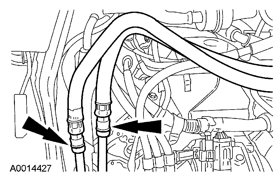
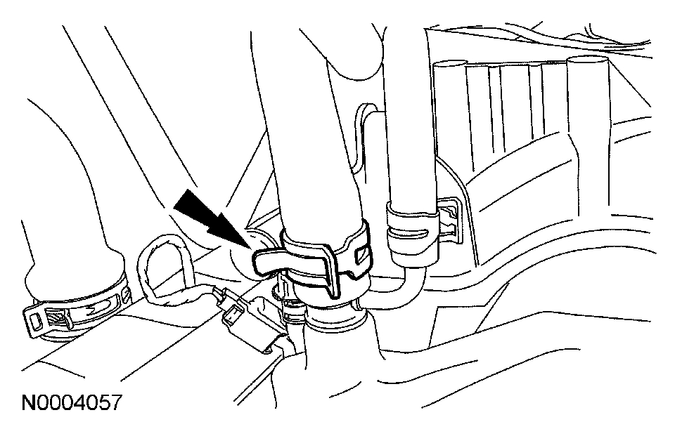
2. Disconnect the fuel supply tube spring lock coupling. For additional information, refer to Fuel Delivery and Air Induction.
3. Disconnect the battery ground cable. For additional information, refer to Battery.
4. Drain the cooling system. For additional information, refer to Cooling System.
5. Remove the throttle body (TB) spacer. For additional information, refer to Fuel Delivery and Air Induction.
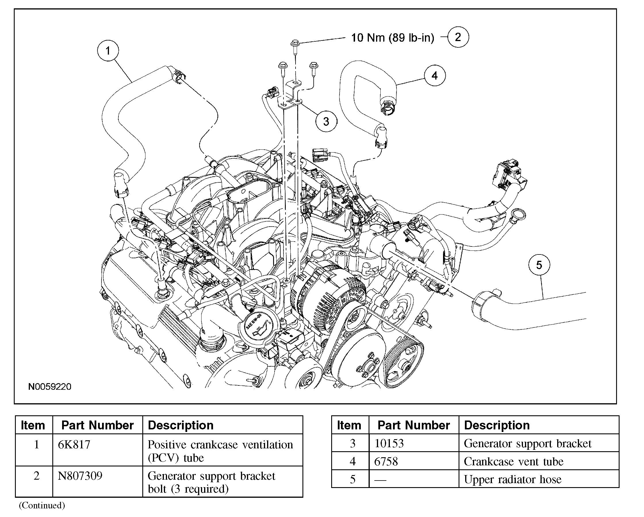
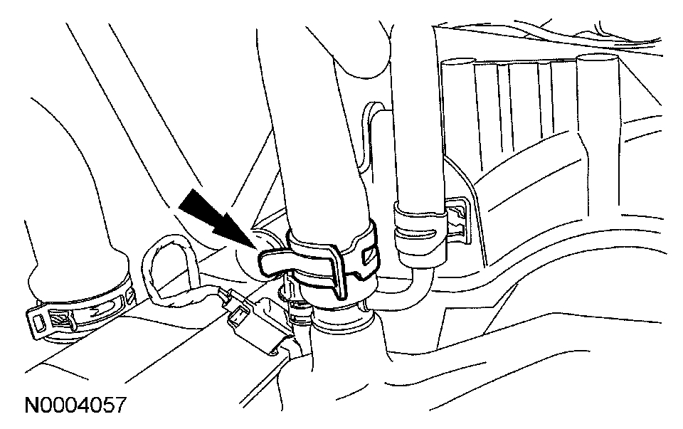
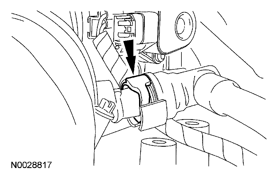
6. Compress and slide the hose clamp and disconnect the upper radiator hose.
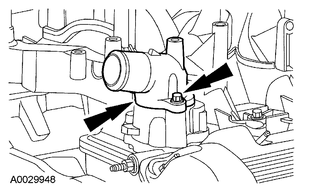
7. Disconnect the coolant hose.
pic 5
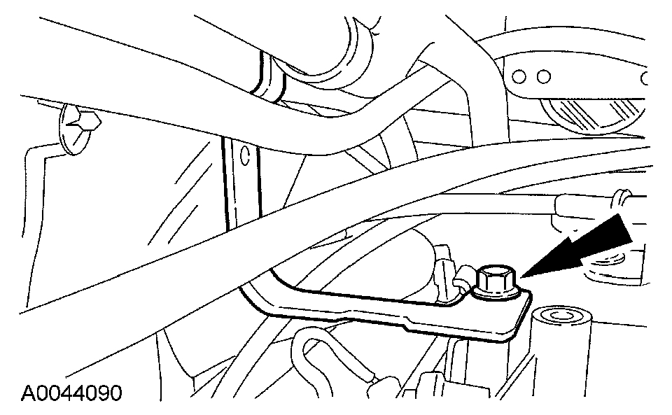
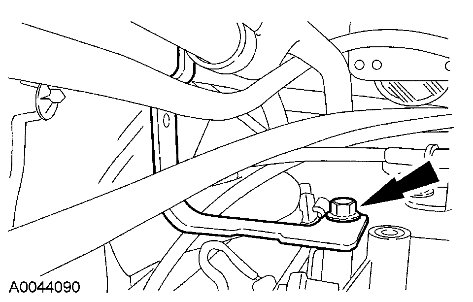
8. Remove the 3 bolts and the generator upper support bracket.
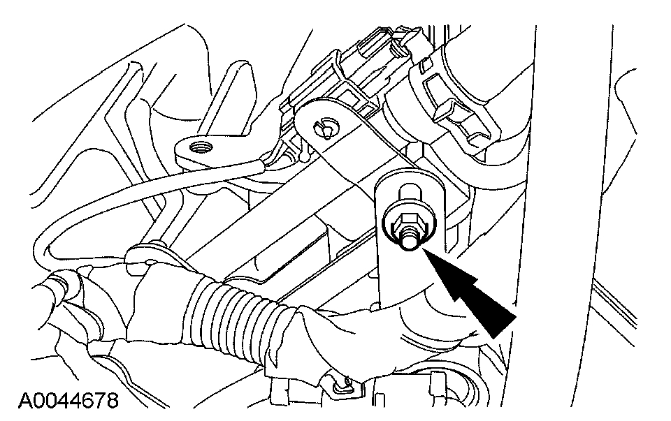
9. Remove the transmission fluid indicator and tube support bracket bolt.
pic 6
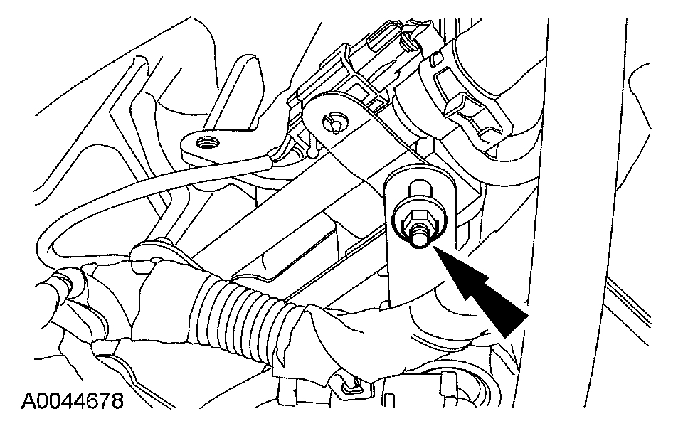
10. Remove the nut and position the transmission fluid indicator and tube aside.
pic 7
11. Disconnect the evaporative emissions (EVAP) tube quick connect coupling from the LH valve cover. For additional information, refer to Fuel Delivery and Air Induction.
12. If equipped, disconnect the auxiliary heater hoses and position aside. For additional information, refer to Heating and Air Conditioning.
pic 8
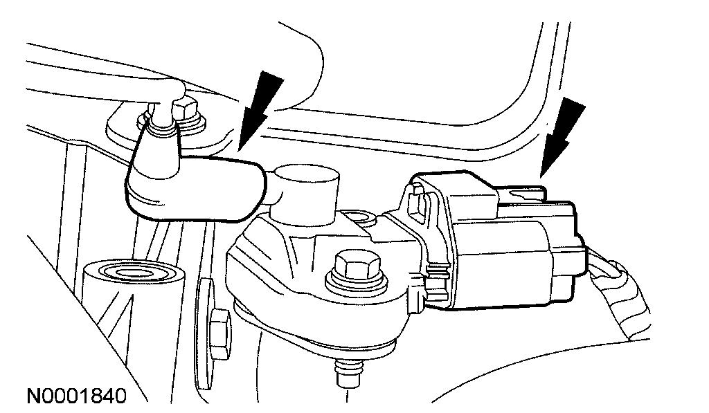
13. Disconnect the quick connect couplings and remove the positive crankcase ventilation (PCV) tube. For additional information, refer to Fuel Delivery and Air Induction.
14. Disconnect the fuel rail pressure and temperature sensor vacuum hose and the electrical connector.
pic 9
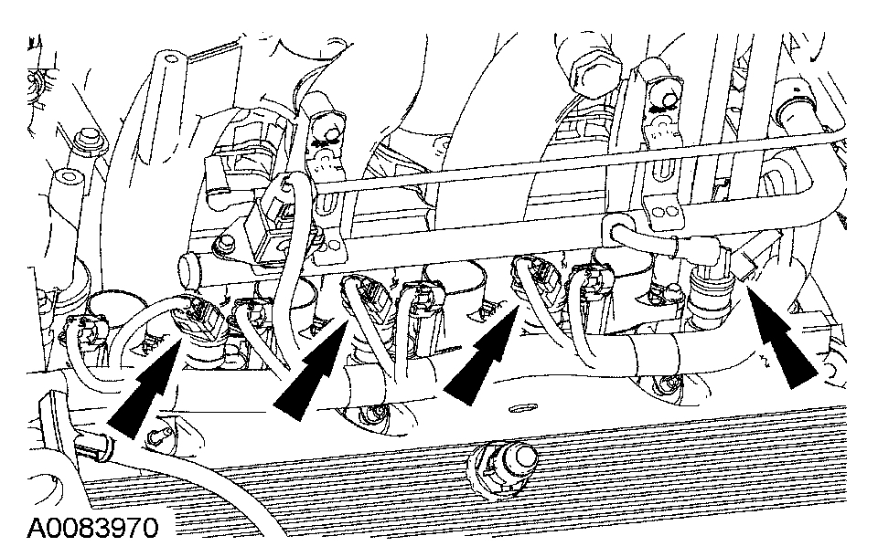
15. NOTE: LH shown, RH similar.
Disconnect the 8 ignition coil electrical connectors.
pic 10
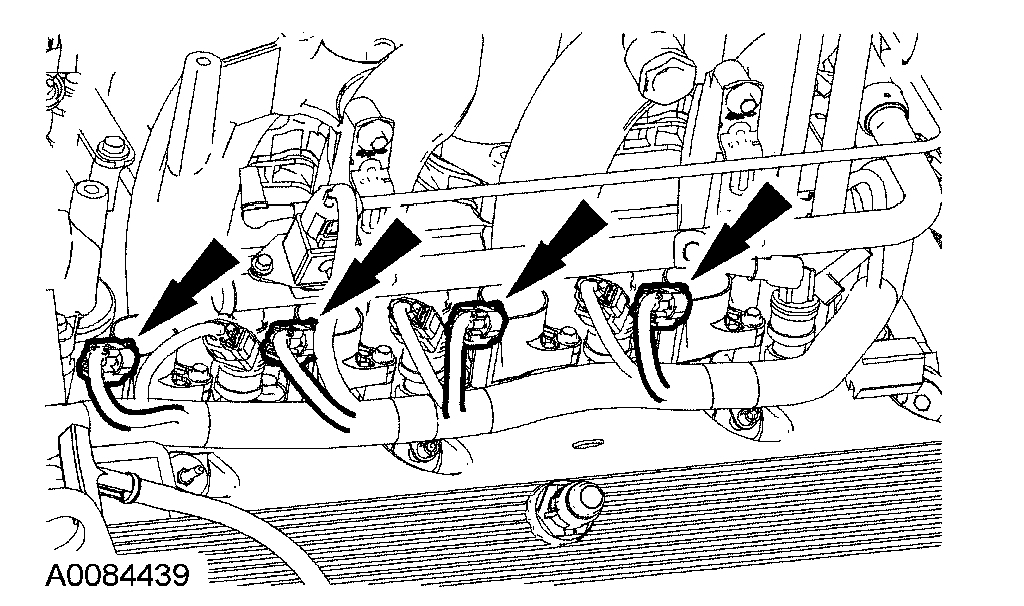
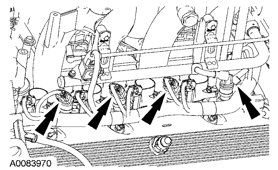
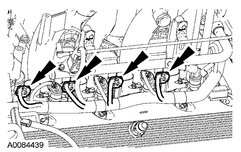
16. NOTE: LH shown, RH similar.
Disconnect the 8 fuel injector electrical connectors.
pic 11
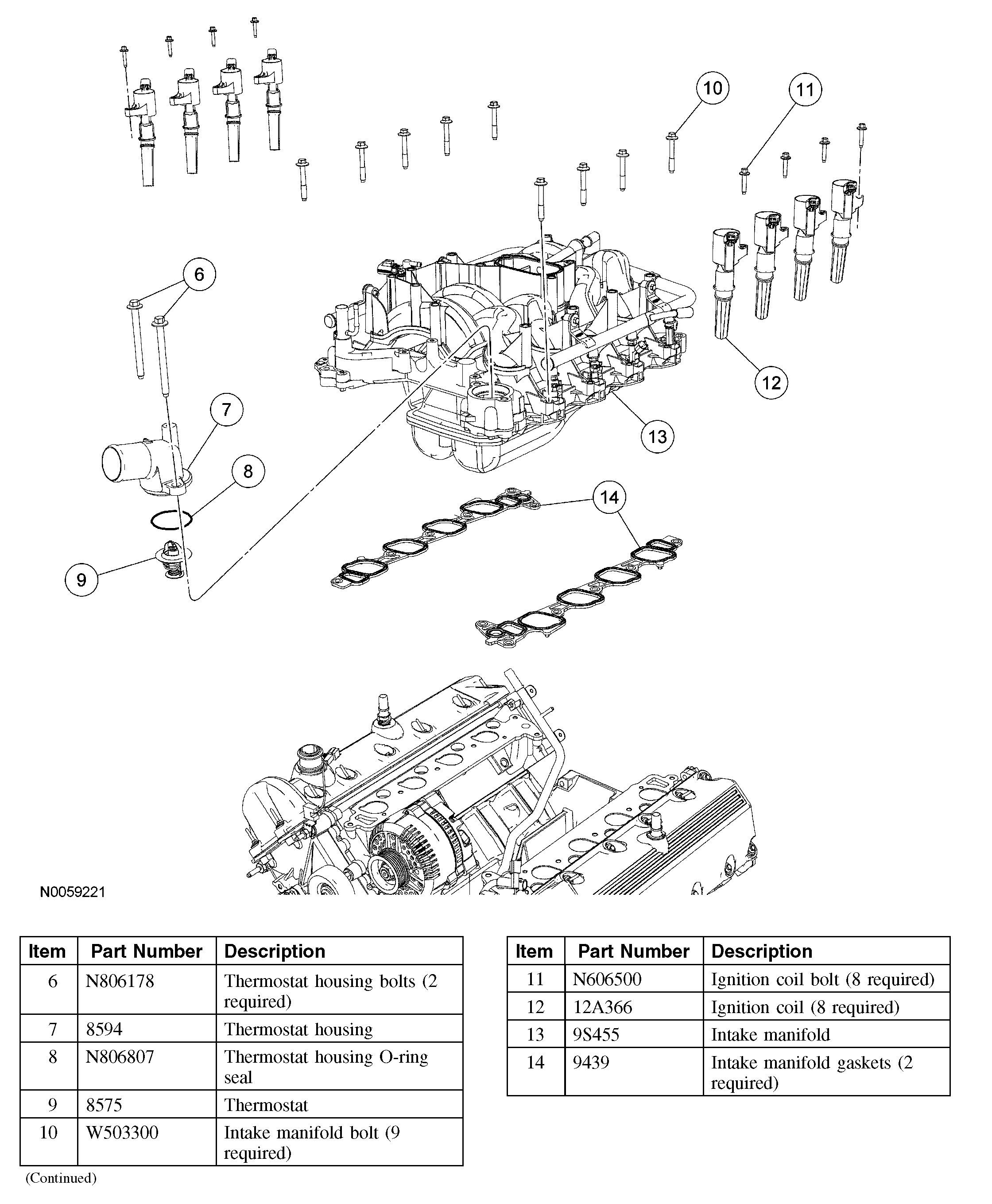
17. Remove the 8 bolts and the 8 ignition coils.
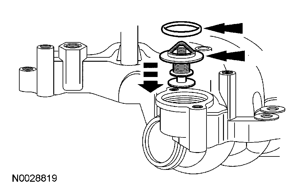
18. Remove the 2 bolts, the thermostat housing and the thermostat.
^ Discard the O-ring seal.
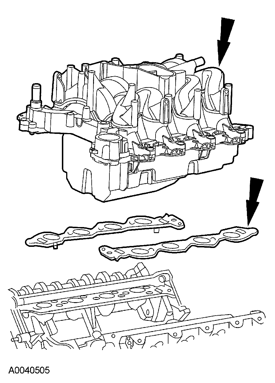
19. Remove the 9 bolts, the intake manifold assembly and discard the intake manifold gaskets.
pic 12
Installation
1. CAUTION: Do not use metal scrapers, wire brushes, power abrasive discs or other abrasive means to clean the sealing surfaces. These tools cause scratches and gouges which can cause leak paths. Use a plastic scraping tool to clean sealing surfaces.
Clean and inspect the sealing surfaces with silicone gasket remover and metal surface prep. Follow the directions on the packaging.
2. Position new intake manifold gaskets, the intake manifold and loosely install the 9 bolts.
3. Using a new O-ring seal, install the thermostat.
pic 13
4. NOTE: The thermostat housing bolts are tightened in sequence with the intake manifold bolts.
Loosely install the thermostat housing and the 2 bolts.
pic 14
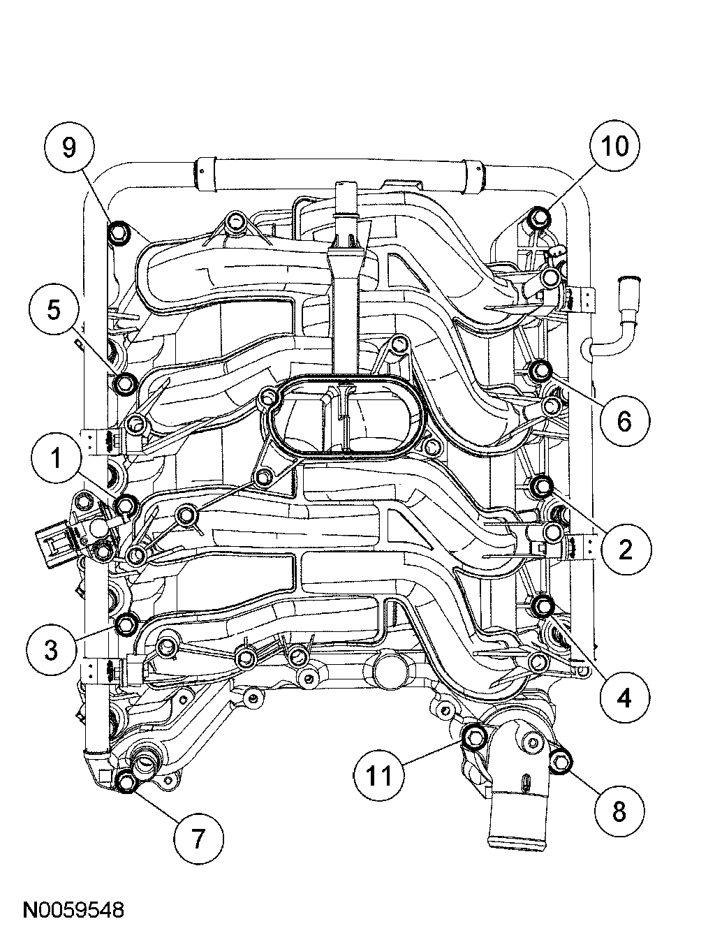
5. Tighten the 11 bolts in 2 stages in the sequence shown.
^ Stage 1: Tighten to 2 Nm (18 inch lbs).
^ Stage 2: Tighten to 25 Nm (18 ft. lbs).
pic 15
6. Install the 8 ignition coils and the 8 bolts.
^ Tighten to 6 Nm (53 inch lbs).
7. NOTE: LH shown, RH similar.
Connect the 8 fuel injector electrical connectors. Position the PCV tube and connect the quick connect couplings. For additional information, refer to Fuel Delivery and Air Induction.
pic 16
8. NOTE: LH shown, RH similar.
Connect the 8 ignition coil electrical connectors.
pic 17
9. Connect the fuel rail pressure and temperature sensor vacuum hose and electrical connector.
pic 18
10. Position the PCV tube and connect quick connect couplings. For additional information, refer to Fuel Delivery and Air Induction.
11. If equipped, connect the auxiliary heater hoses. For additional information, refer to Heating and Air Conditioning.
pic 19
12. Position the transmission fluid indicator and tube and install the retaining nut.
^ Tighten to 28 Nm (21 ft. lbs).
pic 20
13. Install the transmission fluid filler tube support bracket bolt.
^ Tighten to 10 Nm (89 inch lbs).
pic 21
14. Install the generator upper support bracket and the 3 bolts.
^ Tighten to 10 Nm (89 inch lbs).
15. Connect the coolant hose.
pic 22
16. Connect the upper radiator hose.
17. Position the crankcase ventilation tube and connect quick connect coupling to the LH valve cover. For additional information, refer to Fuel Delivery and Air Induction.
pic 23
18. Install the TB spacer. For additional information, refer to Fuel Delivery and Air Induction.
19. Connect the fuel supply tube spring lock coupling. For additional information, refer to Fuel Delivery and Air Induction.
20. Install the engine cover.
21. Connect the battery ground cable. For additional information, refer to Battery.
22. Fill and bleed the engine cooling system. For additional information, refer to Cooling System.
_____________________________
Before doing this, again, confirm it is bad. If it checks good, then we should check fuel pressure next.
https://www.2carpros.com/articles/how-to-check-fuel-system-pressure-and-regulator
I hope this helps. Let me know if you have other questions.
Take care and God Bless,
Joe
Images (Click to enlarge)
Feb 12, 2021 at 5:33 PM