Transmission removal

Tiny
VINOPONTIAC
  • MEMBER
  • 2006 PONTIAC MONTANA
  • 3.5L
  • 6 CYL
  • 2WD
  • AUTOMATIC
  • 120,000 MILES
Any links for transmission removal instructions?
Tuesday, June 2nd, 2020 AT 6:21 AM

11 Replies

Tiny
ASEMASTER6371
  • MECHANIC
  • 52,797 POSTS
Good morning,

I attached a YouTube video of a transmission removal for GM front-wheel drive vans.

You will be required to have a lift, cradle support tool for removal of the cradle and an engine support device for supporting the engine when the cradle is removed.

This is a huge project.

I attached a picture for you. The last bell housing bolt is a hidden bolt. I circled it for you to view.

Roy

https://www.youtube.com/watch?v=uo5QPF-FpP0
Was this
answer
helpful?
Yes
No
Tuesday, June 2nd, 2020 AT 8:58 AM
Tiny
VINOPONTIAC
  • MEMBER
  • 14 POSTS
Thank you, very helpful information.
Was this
answer
helpful?
Yes
No
Tuesday, June 2nd, 2020 AT 9:27 AM
Tiny
ASEMASTER6371
  • MECHANIC
  • 52,797 POSTS
You are welcome.

Always glad to help.

Roy
Was this
answer
helpful?
Yes
No
Tuesday, June 2nd, 2020 AT 9:50 AM
Tiny
VINOPONTIAC
  • MEMBER
  • 14 POSTS
I was able to take out the transmission and rebuild it. I put it back and it runs very smooth expect on first gear, it struggles a lot to engage first gear. I did not touch the valve body which I think was my big mistake. What do you think?
Was this
answer
helpful?
Yes
No
Monday, June 15th, 2020 AT 8:30 AM
Tiny
ASEMASTER6371
  • MECHANIC
  • 52,797 POSTS
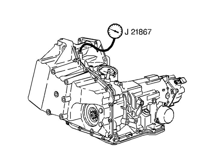
That was a big mistake. You needed to go through the valve body and make sure all the valves move freely.

Did you replace the solenoids while you were there and the internal harness?

Roy

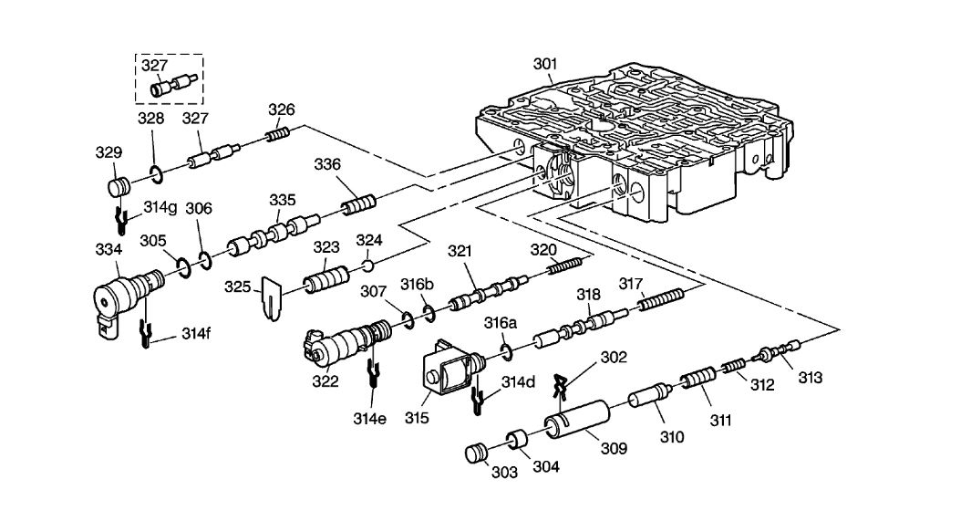
301 - Control Valve Body Machined
302 - Line Boost Valve and Bushing Retainer
303 - Line Boost Valve Bore Plug
304 - Line Boost Valve
305 - TCC PWM Solenoid Valve O-Ring Seal
306 - TCC PWM Solenoid Valve O-Ring Seal
307 - Pressure Control Solenoid Valve O-Ring Seal
309 - Reverse Boost Valve Bushing
310 - Reverse Boost Valve
311 - Pressure Regulator Valve Spring Outer
312 - Pressure Regulator Valve Inner Spring
313 - Pressure Regulator Valve
314d - 1-2, 3-4 Shift Solenoid Valve Retainer
314e - Pressure Control Solenoid Valve Retainer
314f - TCC PWM Solenoid Valve Retainer
314g - TCC Regulator Apply Valve Bore Plug Retainer
315 - 1-2, 3-4 Shift Solenoid Valve Assembly
316a - 1-2, 3-4 Shift Solenoid Valve O-Ring Seal
316b - Pressure Control Solenoid Valve O-Ring Seal
317 - 1-2 Shift Valve Spring
318 - 1-2 Shift Valve
320 - Torque Signal Regulator Valve Spring
321 - Torque Signal Regulator Valve
322 - Pressure Control Solenoid Valve Assembly
323 - Line Pressure Relief Valve Spring
324 - Line Pressure Relief Valve
325 - Line Pressure Relief Valve Spring Retainer
326 - TCC Regulator Apply Valve Spring
327 - TCC Regulator Apply Valve - Some Models have touch activated Power
328 - TCC Regulator Apply Valve Bore Plug O-Ring Seal
329 - TCC Regulator Apply Valve Bore Plug
334 - TCC PWM Solenoid Valve Assembly
335 - TCC Control Valve
336 - TCC Control Valve Spring

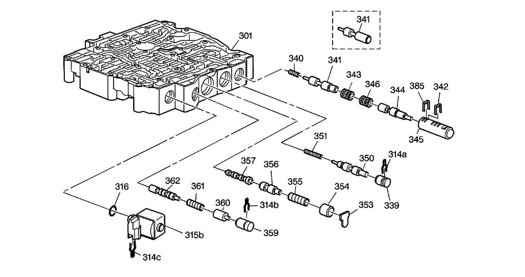
Control Valve Body Assembly - (2 of 2)

Control Valve Body Assembly
imageOpen In New TabZoom/Print

301 - Machined Control Valve Body
314a - 1-2 Accumulator Valve Retainer
314b - 4-3 Manual Downshift Valve Retainer
314c - 2-3 Shift Solenoid Valve Retainer
315b - 2-3 Shift Solenoid Valve Assembly
316 - O-Ring Seal
339 - 1-2 Accumulator Valve Bore Plug
340 - 3-4 Accumulator Valve Spring
341 - 3-4 Accumulator Valve - Some Models have touch activated Power
342 - 2-3 Accumulator Valve Bore Plug Retainer
343 - 2-3 Accumulator Valve Bore Plug
344 - 2-3 Accumulator Valve
345 - 2-3 Accumulator Valve Bushing
346 - 2-3 Accumulator Valve Spring
350 - 1-2 Accumulator Valve
351 - 1-2 Accumulator Valve Spring
353 - 3-2 Manual Downshift Valve Retainer
354 - 3-2 Manual Downshift Valve Bore Plug
355 - 3-2 Manual Downshift Valve Spring
356 - 3-2 Manual Downshift Valve
357 - 2-3 Shift Valve
359 - 4-3 Manual Downshift Valve Bore Plug
360 - 4-3 Manual Downshift Valve
361 - 4-3 Manual Downshift Valve Spring
362 - 3-4 Shift Valve
385 - 2-3 Accumulator Valve Bushing Assembly Retainer
Was this
answer
helpful?
Yes
No
Monday, June 15th, 2020 AT 8:37 AM
Tiny
VINOPONTIAC
  • MEMBER
  • 14 POSTS
No, like I said I did not touch any of that. I am hesitant to go back in there and replace the whole valve body with a new one.
Was this
answer
helpful?
Yes
No
Monday, June 15th, 2020 AT 8:41 AM
Tiny
ASEMASTER6371
  • MECHANIC
  • 52,797 POSTS
The delay going into gear may be from the valve body itself.

Did you replace the vanes on the front pump?

Roy
Was this
answer
helpful?
Yes
No
Monday, June 15th, 2020 AT 8:44 AM
Tiny
VINOPONTIAC
  • MEMBER
  • 14 POSTS
No, mostly I replaced clutches seals and pistons what came in the rebuild kit. :(
Was this
answer
helpful?
Yes
No
Monday, June 15th, 2020 AT 8:48 AM
Tiny
ASEMASTER6371
  • MECHANIC
  • 52,797 POSTS
That is another big mistake. Those vanes are responsible for building the correct pressure for the transmission to work.

Roy
Was this
answer
helpful?
Yes
No
Monday, June 15th, 2020 AT 8:50 AM
Tiny
VINOPONTIAC
  • MEMBER
  • 14 POSTS
Once it gets into second gear the transmission runs very smooth.
Was this
answer
helpful?
Yes
No
Monday, June 15th, 2020 AT 8:54 AM
Tiny
ASEMASTER6371
  • MECHANIC
  • 52,797 POSTS
Okay, the first thing I would do is check the main line pressure. You need at least 150 pounds.

If it is good, then chances are it is either the clutch pack, piston or drum issue.

Roy

LINE PRESSURE CHECK

Tools Required
J 21867 Pressure Gage
J-21867-65 Pressure Test Adapter (5.3 Only)

Important:
Before performing a line pressure check, verify that the pressure control (PC) solenoid valve is receiving the correct electrical signal from the PCM.
Some conditions may be intermittent, therefore this test should be performed at least 3 times.

1. Install a scan tool.

Caution: Keep the brakes applied at all times in order to prevent unexpected vehicle motion. Personal injury may result if the vehicle moves unexpectedly.

2. Start the engine and set the parking brake.
3. Check for a stored Diagnostic Trouble Code (DTC).
4. Repair the vehicle, if necessary.
5. Check the fluid level. Refer to the Transmission Fluid Check. See: Fluid - A/T > Component Tests and General Diagnostics
6. Check the manual linkage for proper adjustment.

ImageOpen In New TabZoom/Print

7. Turn the engine Off.
8. Loosen Exhaust cross-over pipe to allow attachment of J-21867-65 adapter.
9. Remove the oil pressure test hole plug and install the J 21867 and the J-21867-65 adapter if used.
10. Put the gear selector in PARK range and set the parking brake.
11. Start the engine and allow the engine to warm up at idle.

Notice: The total test running time should not be longer than 2 minutes. Running the test longer than 2 minutes may damage the transaxle.

12. Access the PC solenoid valve control test on the scan tool.
13. Increase the PC solenoid actual current from 0 to 1 amps in 0.1 amp increments. Allow the pressure to stabilize for five seconds after each pressure change. Read the corresponding line pressure on the J 21867.
14. Refer to the Line Pressure specification table. Compare the data to the table. See: Automatic Transmission/Transaxle > Pressure, Vacuum and Temperature > Line Pressure
15. If pressure readings differ greatly from the table, refer to Incorrect Line Pressure. See: Automatic Transmission/Transaxle > Symptom Related Diagnostic Procedures > Incorrect Line Pressure
16. Shut the engine OFF. Remove the J 21867 and J-21867-65 if used.
17. Apply sealant GM P/N 12345382 (Canadian P/N 1095348) to the oil pressure test hole plug.

Notice: Use the correct fastener in the correct location. Replacement fasteners must be the correct part number for that application. Fasteners requiring replacement or fasteners requiring the use of thread locking compound or sealant are identified in the service procedure. Do not use paints, lubricants, or corrosion inhibitors on fasteners or fastener joint surfaces unless specified. These coatings affect fastener torque and joint clamping force and may damage the fastener. Use the correct tightening sequence and specifications when installing fasteners in order to avoid damage to parts and systems.

18. Install the oil pressure test hole plug.

Tighten the plug to 12 Nm (106 lb in).

19. Re-tighten the exhaust cross-over pipe (5.3 only).
Was this
answer
helpful?
Yes
No
Monday, June 15th, 2020 AT 9:06 AM

Please login or register to post a reply.

Sponsored links