Welcome to 2CarPros.
First, this model isn't offered in the US, so my technical information is extremely limited. However, the shift indicator on the dash is powered by what is called a transmission range sensor. This sensor is usually mounted to the side of the transmission and sends a signal of the selected gear to the PCM then the indicator in the vehicle.
Since the transmission valve body was recently repaired, I suspect something was left disconnected or damaged related to the range sensor.
The closest thing I have to this vehicle is a Mazda 3. I will attach the directions for removal and replacement of the transmission range sensor. It should at least be similar enough to help you determine if there is an issue.
Here are the directions. The attached pics correlate with the directions.
________________________________________
2004 Mazda 3 L4-2.0L
Transaxle Range (TR) Switch Removal/Installation
1. Remove the battery duct and battery cover.
2. Disconnect the negative battery cable.
3. Remove the under cover.
Caution: Water or foreign material entering the connector can cause a poor connection or corrosion. Be sure not to drop water or foreign material on the connector when disconnecting it.
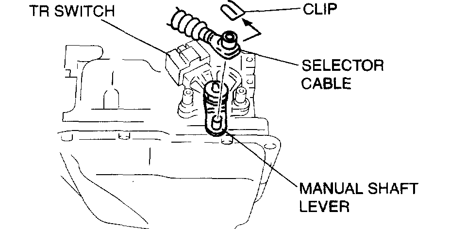
pic 1
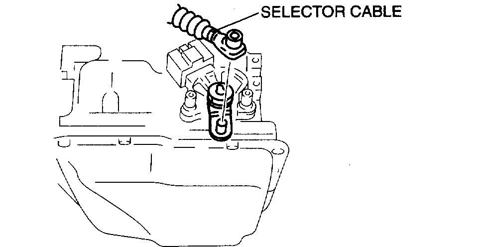
4. Disconnect the TR switch connector.
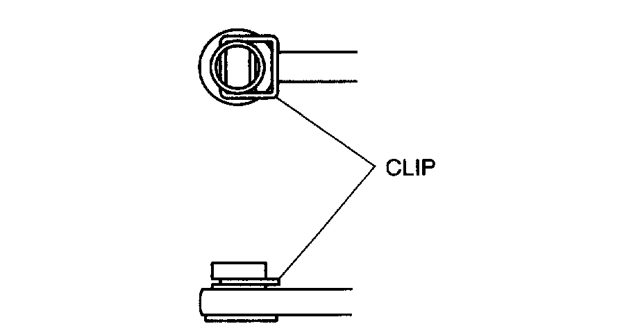
5. Remove the clip and disconnect the selector cable.
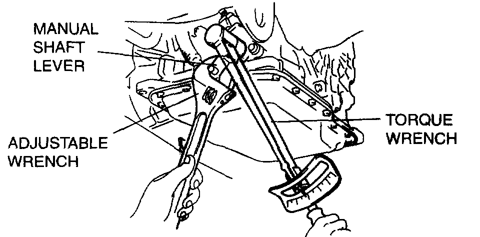
Caution: Do not use an impact wrench. Hold the manual shaft lever when removing the manual shaft nut, or the transaxle may be damaged.
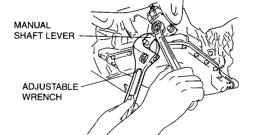
pic 2
6. Set the adjustable wrench as shown in the figure to hold the manual shaft lever.
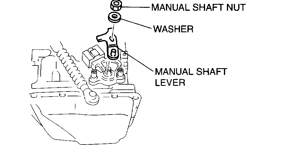
7. Remove the manual shaft nut and washer.
pic 3
8. Remove the manual shaft lever.
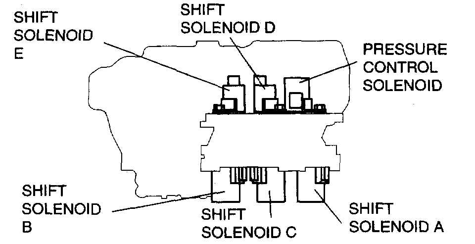
9. Remove the TR switch.
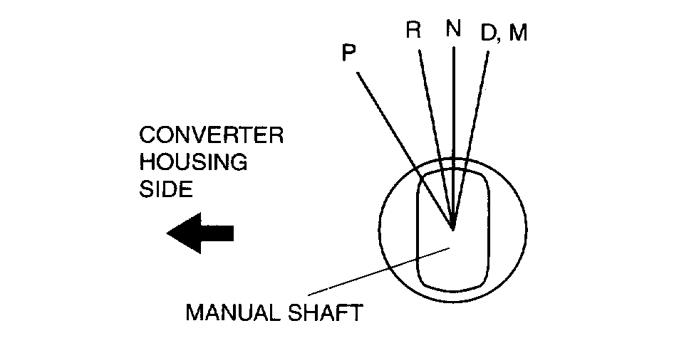
pic 4
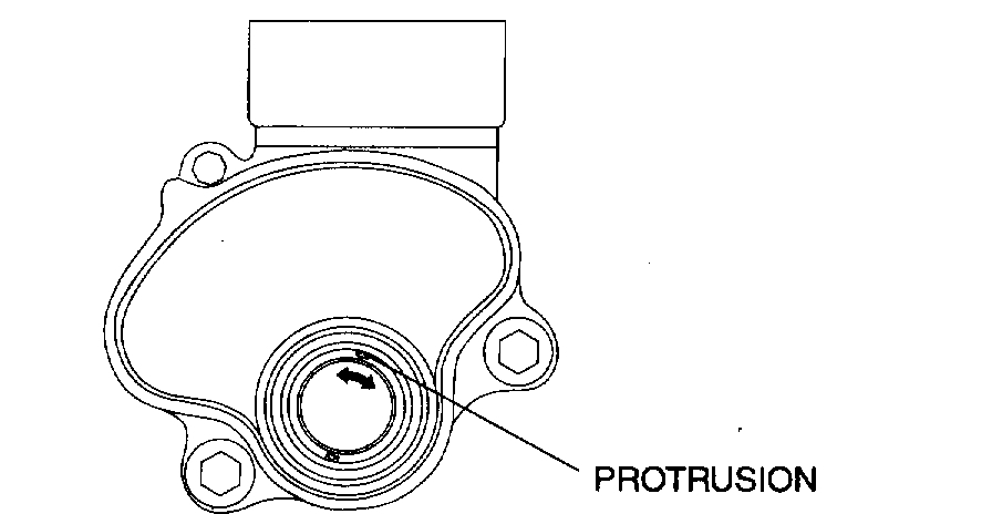
10. Rotate the manual shaft to the converter housing side fully, then return two notches to set the N position.
pic 5
pic 6
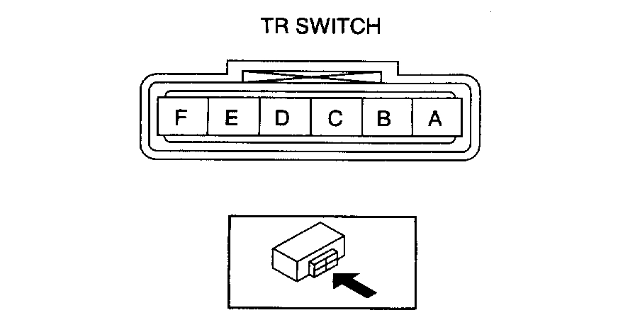
11. Turn the protrusion between the TR switch terminals B and C until the resistance becomes 750 ohms.
pic 7
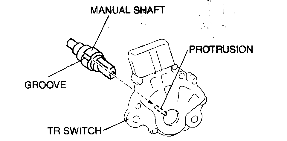
12. Install the TR switch while aligning the protrusion and groove as shown in the figure.
13. Hand-tighten the TR switch mounting bolts.
pic 8
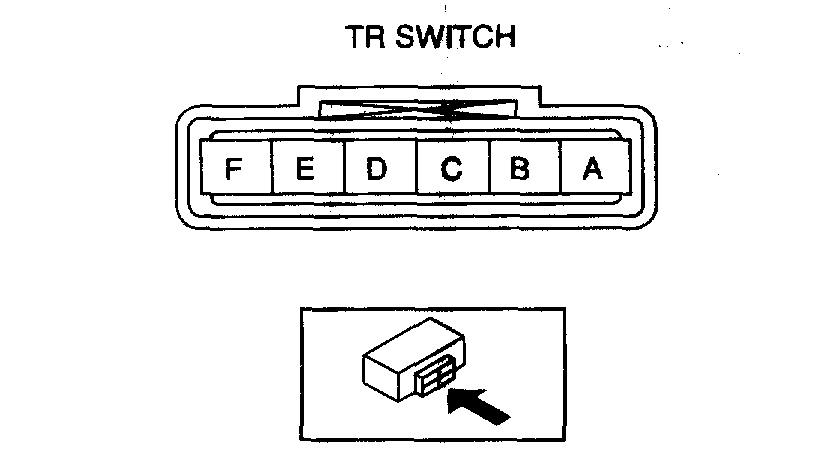
14. Inspect the resistance between the TR switch terminals B and C. If there is any malfunction, readjust the TR switch.
Resistance 750 ohms
15. Tighten the TR switch mounting bolts.
Tightening torque 8 - 11 Nm (82 - 112 kgf-cm, 71 - 97 inch lbs.)
Caution: Do not use an impact wrench. Hold the manual shaft lever when removing the manual shaft nut, or the transaxle may be damaged.
pic 9
16. Install the manual shaft lever and the washer.
pic 10
17. Set the adjustable wrench as shown in the figure to hold the manual shaft lever, and tighten the manual shaft nut.
Tightening torque 31.4 - 46.1 Nm (3.2 - 4.7 kgf-m, 23.2 - 33.9 ft. lbs.)
pic 11
18. Install the clip to the selector cable as shown in the figure.
19. Shift the selector lever to P position.
20. Turn the manual shaft lever to P position.
pic 12
21. Connect the selector cable.
22. Inspect for continuity at the TR switch. If there is any malfunction, readjust the TR switch.
23. Connect the TR switch connector.
24. Install the under cover.
25. Connect the negative battery cable.
26. Install the battery duct and battery cover.
27. Inspect operation of the TR switch. If there is any malfunction, readjust the TR switch.
_______________________
Let me know if this helps.
Take care,
Joe
Images (Click to enlarge)
Oct 15, 2019 at 6:41 PM