Hi,
They are both the 5R55S, but chances are there are differences in how the vehicle will communicate with it. Actually, I looked up part numbers and they differ based on production date. You need to get one specific to your vehicle. I suspect the correct transmission will be based on the production date and the VIN. Today's cars have so many modules, sensors, and so on, I swear they change them every year. THis video will help walk you through the repair on a similar car the process is the same.
https://youtu.be/3vJAojsrfuU
I don't know if you need them, but here are directions for the removal and replacement of the transmission. The attached pics correlate with the directions.
____________________________________
2010 Ford Mustang V6-4.0L
Transmission Removal
Vehicle Transmission and Drivetrain Automatic Transmission/Transaxle Service and Repair Removal and Replacement 5R55S Transmission Removal
TRANSMISSION REMOVAL
Transmission
pic 1
All vehicles
NOTE: When the battery has been disconnected and reconnected, some abnormal drive symptoms can occur while the vehicle relearns its adaptive strategy. The customer needs to be notified that they can experience slightly different upshifts (either soft or firm) and that this is a temporary condition and will eventually return to normal operating condition.
NOTE: If transmission disassembly or installation of a new transmission is necessary, drain the transmission fluid. Install the transmission fluid pan drain plug when finished.
NOTE: If the transmission is to be removed for an extended period of time, support the engine with a safety stand and a wood block.
1. With the vehicle in NEUTRAL, position it on a hoist. For additional information, refer to Vehicle Jacking and Lifting.
2. Disconnect the battery ground cable. For additional information, refer to Battery.
3. Remove the catalytic converter. For additional information, refer to Exhaust System &/or Catalytic Converter.
4. Remove the driveshaft. For additional information, refer to Drive/Propeller Shafts, Bearings and Joints.
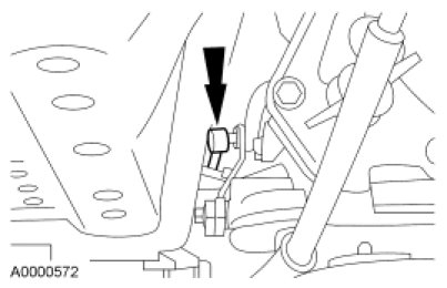
5. Remove the Heated Oxygen Sensor (HO2S) connector from the front of the transmission fluid pan rail.
pic 2
6. Remove the transmission crossmember. For additional information, refer to Frame.
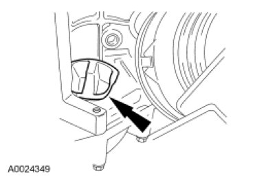
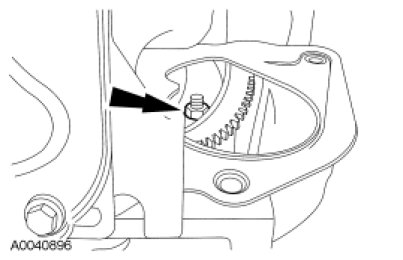
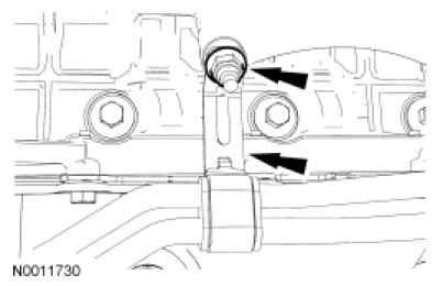
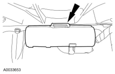
7. Remove the selector lever cable from the transmission manual control lever.
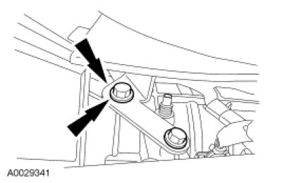
pic 3
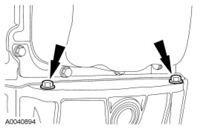
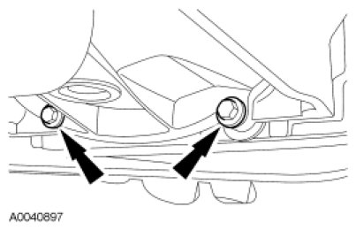
8. Remove the 2 transmission selector lever cable bracket bolts from the transmission and remove the bracket.
pic 4
4.6L engine
9. Remove the starter. For additional information, refer to Starting System.
10. Remove the flexplate cover.
pic 5
11. Remove the access cover.
pic 6
12. Remove and discard the 4 torque converter nuts.
pic 7
4.0L engine
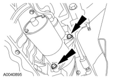
13. Remove the starter and position aside.
pic 8
14. NOTICE: Rotating the crankshaft pulley bolt counterclockwise could cause a reduction in clamp load on the crankshaft pulley and timing sprocket, which could cause severe engine damage.
Remove and discard the 4 torque converter nuts.
pic 9
15. Remove the lower transmission retaining bolts.
pic 10
All vehicles
16. Lower the transmission to gain access to the sensor connectors and the transmission bolts.
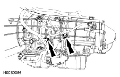
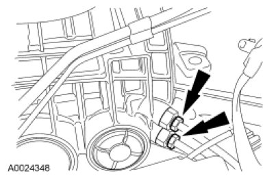
17. Disconnect the Turbine Shaft Speed (TSS) sensor, Output Shaft Speed (OSS) sensor and intermediate shaft speed sensor connectors.
pic 11
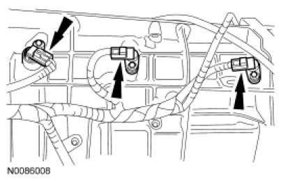
18. Disconnect the transmission vehicle harness retainers.
pic 12
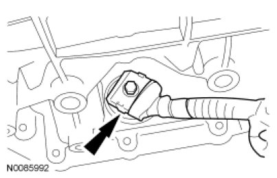
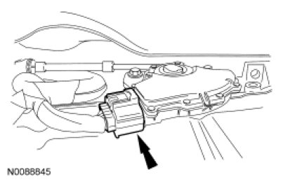
19. Disconnect the Transmission Range (TR) sensor connector.
pic 13
20. NOTE: Clean the area around the connector to prevent contamination of the transmission control solenoid body connector.
Remove the screw from the transmission vehicle harness connector and disconnect the connector.
pic 14
21. NOTICE: Do not damage the cooler tubes.
Remove the transmission fluid cooler tubes.
pic 15
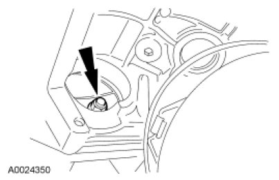
22. Remove the cooler line bracket to engine nut and position aside the transmission fluid cooler tube assembly bracket.
pic 16
4.6L engine
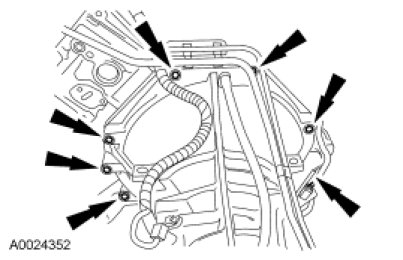
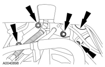
23. Remove the 7 engine-to-transmission retaining bolts.
pic 17
4.0L engine
24. Remove the 6 engine-to-transmission retaining bolts and position the fuel line bracket aside.
pic 18
All vehicles
25. Lower the transmission assembly from the vehicle.
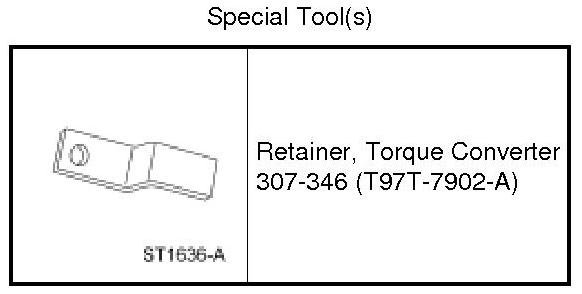
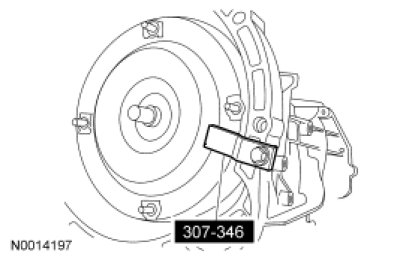
26. Install the Torque Converter Retainer.
pic 19
27. If the transmission is being disassembled to install new parts, or if a new or remanufactured transmission is being installed, the transmission fluid cooler, the auxiliary transmission fluid cooler (if equipped) and the transmission fluid cooler tubes must be cleaned and backflushed to keep contaminants from entering the transmission. For additional information, refer to Transmission Fluid Cooler Backflushing and Cleaning See: Automatic Transmission/Transaxle > Procedures > Transmission Fluid Cooler Backflushing and Cleaning.
______________________________
Install
2010 Ford Mustang V6-4.0L
Transmission Installation
Vehicle Transmission and Drivetrain Automatic Transmission/Transaxle Service and Repair Removal and Replacement 5R55S Transmission Installation
TRANSMISSION INSTALLATION
Transmission
All vehicles
1. WARNING: Secure the assembly to the jack. Avoid any obstructions while lowering and raising the jack. Contact with obstructions may cause the assembly to fall off the jack, which may result in serious personal injury.
Secure the transmission to the transmission jack with a safety chain.
2. Rotate the torque converter and adapter plate so the orange or green paint daub on the torque converter is in the 12 o'clock location.
3. Raise and position the transmission to the back of the engine.
4.6L engine
4. Install the 7 engine-to-transmission retaining bolts.
- Tighten to 48 Nm (35 lb-ft).
pic 20
5. Install the 4 new torque converter nuts.
- Tighten to 44 Nm (32 lb-ft).
pic 21
6. Install the access cover.
pic 22
7. Install the flexplate cover.
- Tighten to 35 Nm (26 lb-ft).
pic 23
8. Install the starter. For additional information, refer to Starting System.
4.0L engine
9. Position the fuel line bracket in place and install the 6 engine-to-transmission retaining bolts.
- Tighten to 48 Nm (35 lb-ft).
pic 24
10. NOTICE: Rotating the crankshaft pulley bolt counterclockwise could cause a reduction in clamp load on the crankshaft pulley and timing sprocket, which could cause severe engine damage.
Install the 4 new torque converter nuts.
- Tighten to 44 Nm (32 lb-ft).
pic 25
11. NOTE: Clean the starter motor mounting flange and mating surface of the starter motor to make sure there is a correct ground connection.
Install the starter motor.
- Tighten to 25 Nm (18 lb-ft).
pic 26
12. Install the lower transmission retaining bolts.
- Tighten to 48 Nm (35 lb-ft).
pic 27
All vehicles
13. NOTICE: Use care not to bend or force the transmission fluid cooler tubes, otherwise, damage to the transmission fluid cooler tubes and the transmission may result.
Install the transmission fluid cooler tubes.
- Tighten to 40 Nm (30 lb-ft).
pic 28
14. Install the transmission fluid cooler tube assembly bracket and nut.
- Tighten to 25 Nm (18 lb-ft).
pic 29
15. Connect the Transmission Range (TR) sensor connector.
pic 30
16. NOTICE: Damage will occur to the transmission control solenoid body assembly if the screw is tightened above the specification.
NOTE: Always install new O-ring seals on the transmission vehicle harness connector.
NOTE: Clean the area around the transmission control solenoid body connector to prevent contamination of the transmission control solenoid body connector.
NOTE: Use petroleum jelly to lubricate the O-ring seals to aid in the installation process.
Install and lubricate new O-ring seals on the transmission vehicle harness connector and connect the connector.
- Tighten to 5 Nm (44 lb-in).
pic 31
17. Position the transmission vehicle harness and install the retainers.
pic 32
18. Connect the Turbine Shaft Speed (TSS) sensor, Output Shaft Speed (OSS) sensor and intermediate shaft speed sensor connectors.
pic 33
19. Install the selector lever cable bracket and install the 2 bolts.
- Tighten to 28 Nm (21 lb-ft).
pic 34
20. Install the selector lever cable onto the transmission manual lever.
pic 35
21. Install the transmission crossmember. For additional information, refer to Frame.
22. Install the Heated Oxygen Sensor (HO2S) connector to the front of the transmission fluid pan rail.
pic 36
23. Install the driveshaft. For additional information, refer to Drive/Propeller Shafts, Bearings and Joints.
24. Install the catalytic converter. For additional information, refer to Exhaust System &/or Catalytic Converter.
25. Use the following guidelines for installing the in-line transmission fluid filter:
- If the transmission was overhauled and the vehicle was equipped with an in-line fluid filter, install a new in-line fluid filter.
- If the transmission was overhauled and the vehicle was not equipped with an in-line fluid filter, install a new in-line fluid filter kit.
- If the transmission is being installed for a non-internal repair, do not install an in-line filter or filter kit.
- If installing a new or a Ford-authorized remanufactured transmission, install the in-line transmission fluid filter that is supplied.
- Prior to lowering the vehicle, install a new in-line transmission filter or a filter kit. For additional information, refer to Transmission Filter - In Line See: Fluid Filter - A/T > Removal and Replacement > Transmission Filter - In Line.
26. NOTE: When the battery has been disconnected and reconnected, some abnormal drive symptoms can occur while the vehicle relearns its adaptive strategy. The customer needs to be notified that they can experience slightly different upshifts (either soft or firm) and that this is a temporary condition and will eventually return to normal operating condition.
Connect the battery ground cable.
27. Carry out the fluid level check. For additional information, refer to Transmission Fluid Level Check See: Automatic Transmission/Transaxle > Procedures > Transmission Fluid Level Check.
28. Verify that the selector lever cable is correctly adjusted. For additional information, refer to Automatic Transmission/Transaxle.
29. Check the operation of the transmission and inspect for leaks.
____________________________
I hope this helps. Let me know if you have other questions.
Take care and God Bless,
Joe
Images (Click to enlarge)
Feb 24, 2021 at 9:18 PM